WWW.COMBISAFE.COM
5
WARNING:
Check that the ground on which the staircase Escalib is to be erected is able to withstand the load.
WARNING:
Comply with the general rules for handling and stability.
1 - The base must be oriented
according to the height of the floor
which needs to be accesed.
Start the installation 8 cm away from
the wall to facilitate pivoting of the
guardrails at the access level.
Level the base.
2 - Access inside the module is
available for attaching the sling
to the center ring, for putting the
guardrails in closed position and
putting the erection rails in hori-
zontal position.
3- Fitting the module to the base.
Assembly of the 4 uprights with
M24 screws. Sling released.
4 - Installing a new module.
5- Erection guardrail
rotated to vertical
position and locked
onto stair above.
Bolt the uprights
together using M24
screws.
Slings released.
Repeat steps 2, 4 and 5 if needed
while anchoring the Escalib as
the height is increased.
REQUIREMENTS:
> Fit new anchorages as
new modules are added.
> Dismantle in the reverse
order of assembly.
Fixings:
- Module and base: M24x35-8-8
hex head screw + washer.
- Barrier gate: M16x100 hex
head bolt
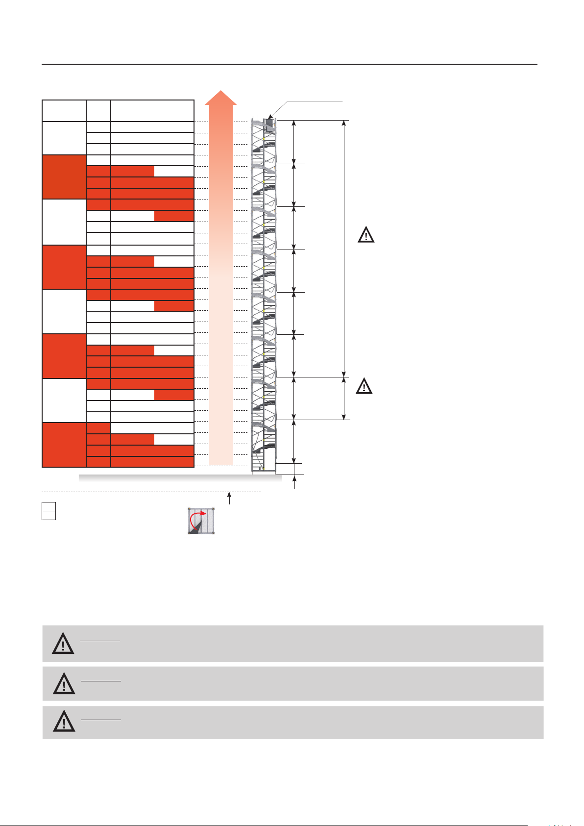
Start bolting with the new
module’s first step (corner
A-D) and then continue clo-
ckwise.
InTermedIaTe modules
Example of an Escalib with 3 modules.
ASSEMBLING AND DISMANTLING