Metreel MET-TRACK Installation and operating instructions
TOLL Free Tel:
877-830-9803
Email:
sales@metreel.com
Website:
www.metreel.com
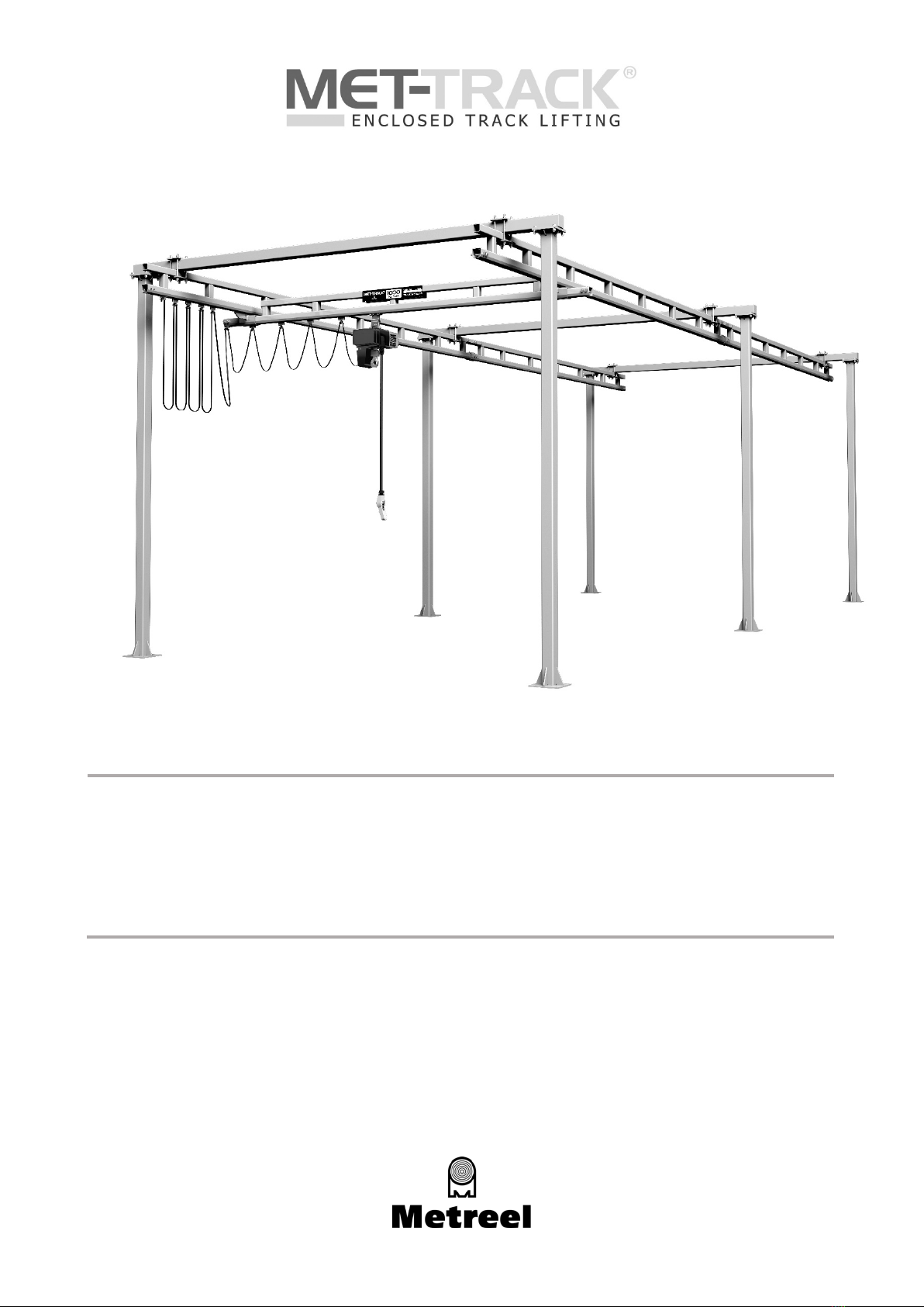
MET-TRACK®Workstation Bridge Cranes
FLOOR MOUNTED
Installation & Maintenance Instructions

Floor Mounted Workstation Bridge Crane
Installation & Maintenance Instructions
Document No. TD002-0618
Last Updated: 14 June 2018
Page 2of 29
CONTENTS
Introduction............................................................................................................................................ 3
Preparation............................................................................................................................................. 3
Column and Header Installation............................................................................................................4-5
Runway Installation..............................................................................................................................6-8
Bridge & End Truck Options and Parts Breakdown................................................................................ 9-17
Hoist Trolley and Bridge Festoon Installation .......................................................................................... 18
Festoon Storage Extensions (FSE)......................................................................................................19-20
Hoist Trolley Installation........................................................................................................................ 20
Service Connections .............................................................................................................................. 21
Final Steps............................................................................................................................................ 21
Warning, Safety or Capacity Labels ........................................................................................................ 21
Load Testing......................................................................................................................................... 21
Sway Bracing (Optional)........................................................................................................................ 22
Operator Instructions ...................................................................................................................23-24
Inspection and Maintenance Schedule........................................................................................25-28
Warranty Statement ......................................................................................................................... 29

Floor Mounted Workstation Bridge Crane
Installation & Maintenance Instructions
Document No. TD002-0618
Last Updated: 14 June 2018
Page 3of 29
INTRODUCTION
Thank you for choosing a MET-TRACK® Floor Mounted Workstation Kit Crane from Metreel. We really
appreciate your choice and are confident that, when installed correctly this product will provide you with a
superior materials handling solution. All of our cranes are designed and engineered for a powered hoist
operation, however manual hoists, balancers and any other lifting equipment can be used as long as the
duty is within our standard capacity. If you are unsure about his point then please contact our technical
team on Toll Free 877-830-9803 or email sales@metreel.com
Within our design criteria we have allowed 15% for the weight of the hoist, for example with a 500lb crane,
the hoist unit itself should be no heavier than 75lb. There is also an allowance with the design for normal
impact loading caused by the bridge and hoist movement.
To ensure that you continue to get many years of service from the MET-TRACK® Workstation Crane we
advise that a good inspection / maintenance routine according to our procedures detailed herein must be
adopted.
Dimensions contained in this document and any literature is for guidance only and may differ from the crane
delivered. Please ensure you refer to the General Arrangement Drawing for actual dimensions.
PREPARATION
Before starting the install of this crane it is recommended that you ensure that you have all the materials
required.
We recommend you follow the following steps and confirm you have all items.
1) Confirm all the following documents are present, these will be found in the component box marked
“Contains Documentation”
a) Packing List
b) Installations & Maintenance Manual
c) General Arrangement Drawing
2) Check all items against the packing list
3) Check that you have the correct anchors bolts, refer to Page 2. These are supplied with the crane kit
4) Check that the area in which the crane is to be installed is clean and free of obstructions
5) Check that you have all the required tools and materials needed to assemble the crane, these will
typically include:
a) Torque Wrench
b) General Tools
c) Measure
d) Chalk Line
e) Level
f) Shims
g) Heavy duty drill & bits
h) Steps/Ladders/Man Lifts
i) Lifting equipment for heavier sections
Floor Mounted Workstation Bridge Crane
Installation & Maintenance Instructions
Document No. TD002-0618
Last Updated: 14 June 2018
Page 4of 29
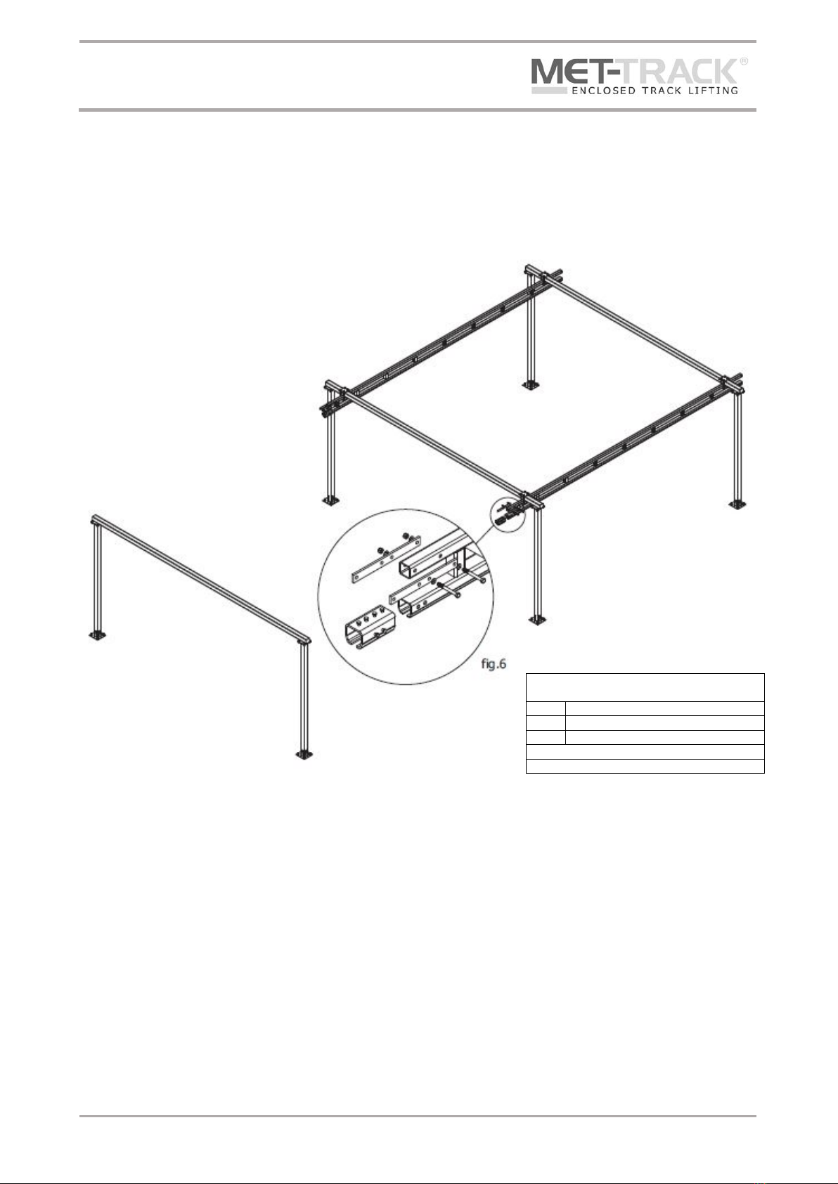
COLUMN & HEADER INSTALLATION
1) Layout and mark the area where the crane is to be installed (refer to the General Arrangement Drawing
for dimensions)
2) Mark out the floor BEFORE drilling using the column bas plate as a template (or refer to the General
Arrangement Drawing for dimensions). Brush away the dust and debris
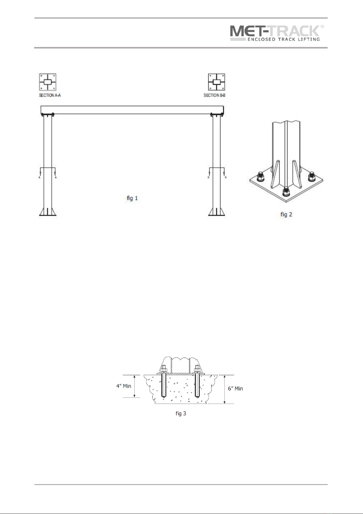
3) Bolt the first set of columns to the floor, ensuring they are aligned correctly to receive the header (in
case of rectangular columns, ensure the column rotation is as shown in fig1)
a) 4 off ¾” Ø bolts grade 5 or greater MUST be used per column (See fig 2)
b) These MUST be embedded at least 4” into a minimum 6” thick reinforced concrete floor (See fig 3)
c) A minimum of two threads MUST be visible above the nut after tightening
d) Chemical anchor bolts are recommended (not supplied)
4) Check that the column is plumb and level, if not loosen the hardware and place steel shims (not
included) or grout (not included) under base of column until plumb. Once plumb retighten hardware.
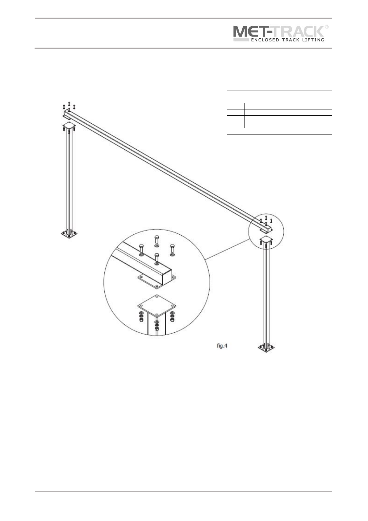
5) Lift and position header using appropriate lifting equipment and fasten the 5/8” x 2” bolt assemblies
supplied (torque to 154ft.-lb) (See fig 4)
Floor Mounted Workstation Bridge Crane
Installation & Maintenance Instructions
Document No. TD002-0618
Last Updated: 14 June 2018
Page 5of 29
6) Follow the same procedure for the remaining column and header sets
Fixings Parts List
Column to Header Beam (per column)
4 x
5/8” x 2” Bolt
4 x
5/8” Nut
4 x
Type B ‘Narrow’ 5/8” Washer
4 x
Regular 5/8” Spring Washer
All fixings must be UNC
All fixings must be SAE Grade 5
Floor Mounted Workstation Bridge Crane
Installation & Maintenance Instructions
Document No. TD002-0618
Last Updated: 14 June 2018
Page 6of 29
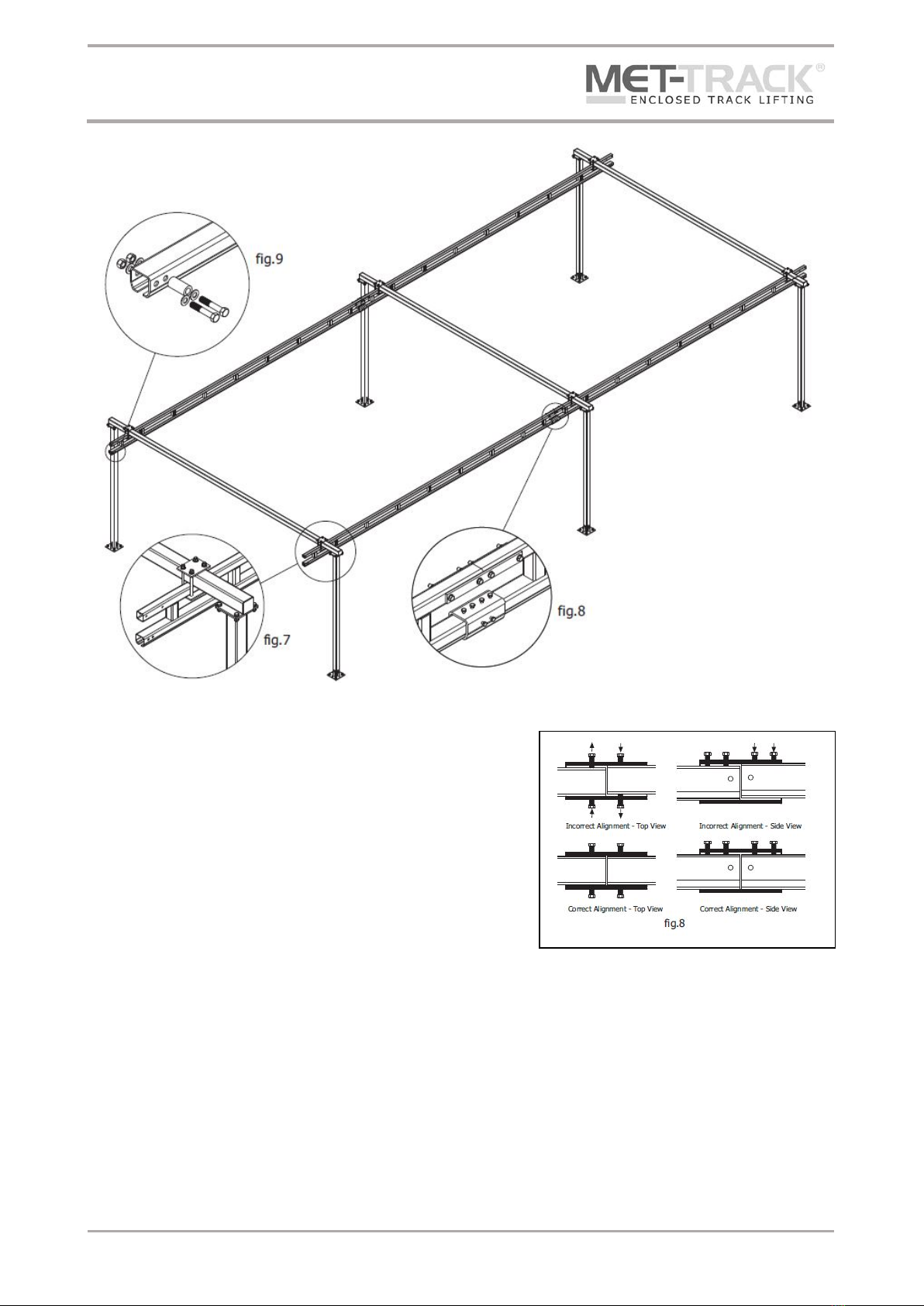
RUNWAY INSTALLATION
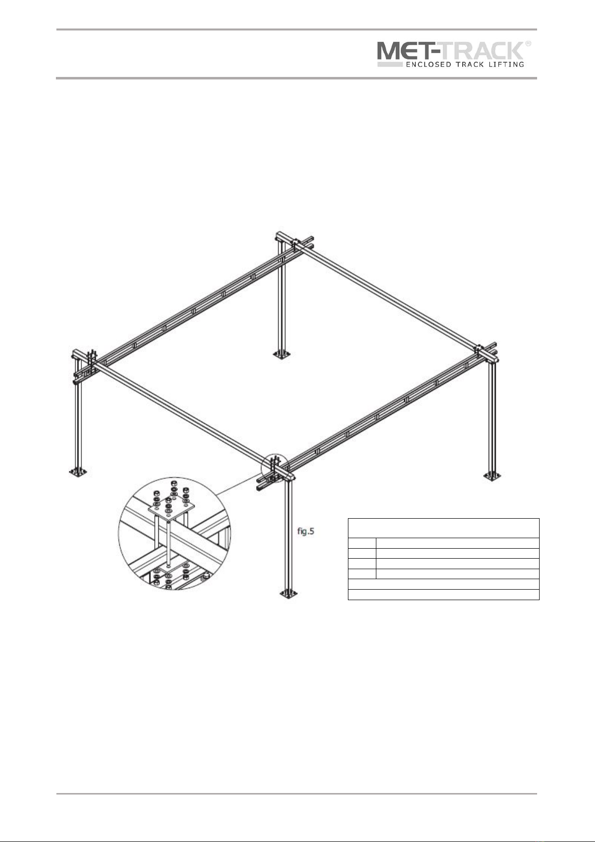
1) As the runway sections maybe different depending upon your span selection, check the General
Arrangement Drawing to identify individual gantry sections
2) Being careful not to disturb the columns, lift the first set of runway sections into place (refer to the
General Arrangement Drawing for position and dimension details)
3) Using the runway fixing brackets secure the runway to the header (see fig 5)
4) Do not alter the span (CBS) from that advised in the General Arrangement Drawing and take care to
position the runway centrally or as per the dimensions provided
5) Do not cantilever the end of the runways further than the dimension stated in the General Arrangement
Drawing
6) Check to ensure that the runways are parallel, failure to do so will prevent the bridge from running
smoothly
Fixings Parts List
Runway to Header Fixing Kits (per column)
8 x
5/8” Nut
8 x
Type B ‘Narrow’ 5/8” Washer
8 x
Regular 5/8” Spring Washer
4 x
Studding (length to suit)
All fixings must be UNC
All fixings must be SAE Grade 5
Floor Mounted Workstation Bridge Crane
Installation & Maintenance Instructions
Document No. TD002-0618
Last Updated: 14 June 2018
Page 7of 29
7) Torque fasteners to 75ft.-lb and ensure at least two treads are visible after tightening
8) If you have no more runways to install then skip to step 16
9) Install Joint Kits to previously installed runway (See fig 6)
10) Install the next runway length by lifting and bringing together the runway ends and positioning
according to the General Arrangement Drawing. The gap between the running profile MUST not exceed
1/16”
11) Attach the other end of the runway to the next header using the runway fixing brackets (See fig 7)
Fixings Parts List
Track Joints (per Joints)
4 x
½” (length to suit) Bolt
4 x
½” Type B ‘Narrow’ Flat Washer
4 x
½” Nylon Nut, fixing torque 78ft.-lbs
All fixings must be UNC
All fixings must be SAE Grade 5
Floor Mounted Workstation Bridge Crane
Installation & Maintenance Instructions
Document No. TD002-0618
Last Updated: 14 June 2018
Page 8of 29
12) Align the runway profile so that the running surfaces are
level
a) To adjust for smooth travel, use the bolts on the top of
the splice joint to force the track down into the base of
the splice joint. Use the bolts on each side to level the
track laterally (see fig 8)
13) Fix final hardware in the splice plates and secure
14) Once secure torque the runway fix bracket fasteners to
170ft.-lb and ensure at least two threads are visible after
tightening
15) For additional runway sections refer to Step 9 through to Step 15 until runway installation is complete
16) Fit runway End Kits at one end of each runway, opposite to where the bridge will be installed (See fig 9)
17) Clean the inside of the runway flanges with a clean, dry cloth to remove grit or debris

Floor Mounted Workstation Bridge Crane
Installation & Maintenance Instructions
Document No. TD002-0618
Last Updated: 14 June 2018
Page 9of 29
BRIDGE & END TRUCK OPTIONS AND PARTS BREAKDOWN Please ensure you have the correct End Truck
Standard End Truck
Part No.
1454
1554
1654
1754
Cap.(lbs)
250
500
1000
2000
Bridge
Length
Upto 23ft
1454L End Truck
Description
Qty
Part No.
400 Series Splice Plate Weldment
1
23618
SHS for 400 Series Extended Trolley
2
23605
Trolley for 400 Series Extended Truck
2
23622
Plastic End Cap
4
GPN 260 Q 4040 4
End Truck Fixing Kit 2
2
28035
End Truck Fixing Kit 1
4
28034
1554L End Truck
Description
Qty
Part No.
500 Series Splice Plate Weldment
1
23619
SHS for 500 Series Extended Trolley
2
23606
Trolley for 500 Series Extended Truck
2
23623
Plastic End Cap
4
GPN 260 Q 5050 5
End Truck Fixing Kit 3
6
28036

Floor Mounted Workstation Bridge Crane
Installation & Maintenance Instructions
Document No. TD002-0618
Last Updated: 14 June 2018
Page 10 of 29
1654L End Truck
Description
Qty
Part No.
600 Series Splice Plate Weldment
1
23620
SHS for 600 Series Extended Trolley
2
23624
Trolley for 600 Series Extended Truck
2
23607
Plastic End Cap
4
GPN 260 Q 5050 5
End Truck Fixing Kit 3
6
28036
1754L End Truck
Description
Qty
Part No.
700/800 Series Splice Plate Weldment
1
23621
SHS for 700 Series Extended Trolley
2
23608
Trolley for 700 Series Extended Truck
2
23625
Plastic End Cap
4
GPN 260 Q 6060 5
End Truck Fixing Kit 4
6
28037
1854L End Truck
Description
Qty
Part No.
700/800 Series Splice Plate Weldment
1
23621
SHS for 800 Series Extended Trolley
2
23609
Trolley for 800 Series Extended Truck
2
23626
Plastic End Cap
4
GPN 260 Q 6060 5
End Truck Fixing Kit 4
6
28037
Floor Mounted Workstation Bridge Crane
Installation & Maintenance Instructions
Document No. TD002-0618
Last Updated: 14 June 2018
Page 11 of 29
1554-400 End Truck
Description
Qty
Part No.
400 Series Splice Plate Weldment
1
23618
Packer Plates for End Truck Designs
4
23629
Plastic End Cap
4
GPN 260 Q 5050 5
Trolley for 500 Series Extended End Truck
2
23623
SHS for 1554-400 & 1554 End Trucks
2
28024
End Truck Fixing Kit 3
6
28036
1654-400 End Truck
Description
Qty
Part No.
400 Series Splice Plate Weldment
1
23618
Packer Plates for End Truck Designs
8
23629
Plastic End Cap
4
GPN 260 Q 5050 5
600 Series Extended End Truck
2
23624
SHS for 1654-400 & 1654 End Trucks
2
28025
End Truck Fixing Kit 4
6
28036
1754-400 End Truck
Description
Qty
Part No.
Truck Plate Weldment for 1754-400 End Truck
1
28029
Packer Plates for End Truck Designs
16
23629
Trolley for 700 Extended End Truck
2
23625
SHS for 1754-400 End Truck
2
28027
Plastic End Cap
4
GPN 260 Q6060 5
End Truck Fixing Kit 4
6
28037

Floor Mounted Workstation Bridge Crane
Installation & Maintenance Instructions
Document No. TD002-0618
Last Updated: 14 June 2018
Page 12 of 29
1654-500 End Truck
Description
Qty
Part No.
500 Series Splice Plate Weldment
1
23621
Packer Plates for End Truck Designs
4
23629
Plastic End Cap
4
GPN 260 Q 5050 5
600 Series Extended End Truck
2
23624
SHS for 1654-400 & 1654 End Trucks
2
28025
End Truck Fixing Kit 3
6
28036
1754-500 End Truck
Description
Qty
Part No.
500 Series Splice Plate Weldment
1
23619
Packer Plates for End Truck Designs
12
23629
Plastic End Cap
6
GPN 260 Q 6060 5
Trolley for 700 Extended End Truck
4
23625
SHS for 1754-500 & 1754-600 End Trucks
2
28026
End Truck Fixing Kit 4
6
28037
1754-600 End Truck
Description
Qty
Part No.
600 Series Splice Plate Weldment
1
23620
Packer Plates for End Truck Designs
8
23629
Plastic End Cap
4
GPN 260 Q 6060 5
Trolley for 700 Extended End Truck
2
23625
SHS for 1754-500 & 1754-600 End Trucks
2
28026
End Truck Fixing Kit 4
6
28037

Floor Mounted Workstation Bridge Crane
Installation & Maintenance Instructions
Document No. TD002-0618
Last Updated: 14 June 2018
Page 13 of 29
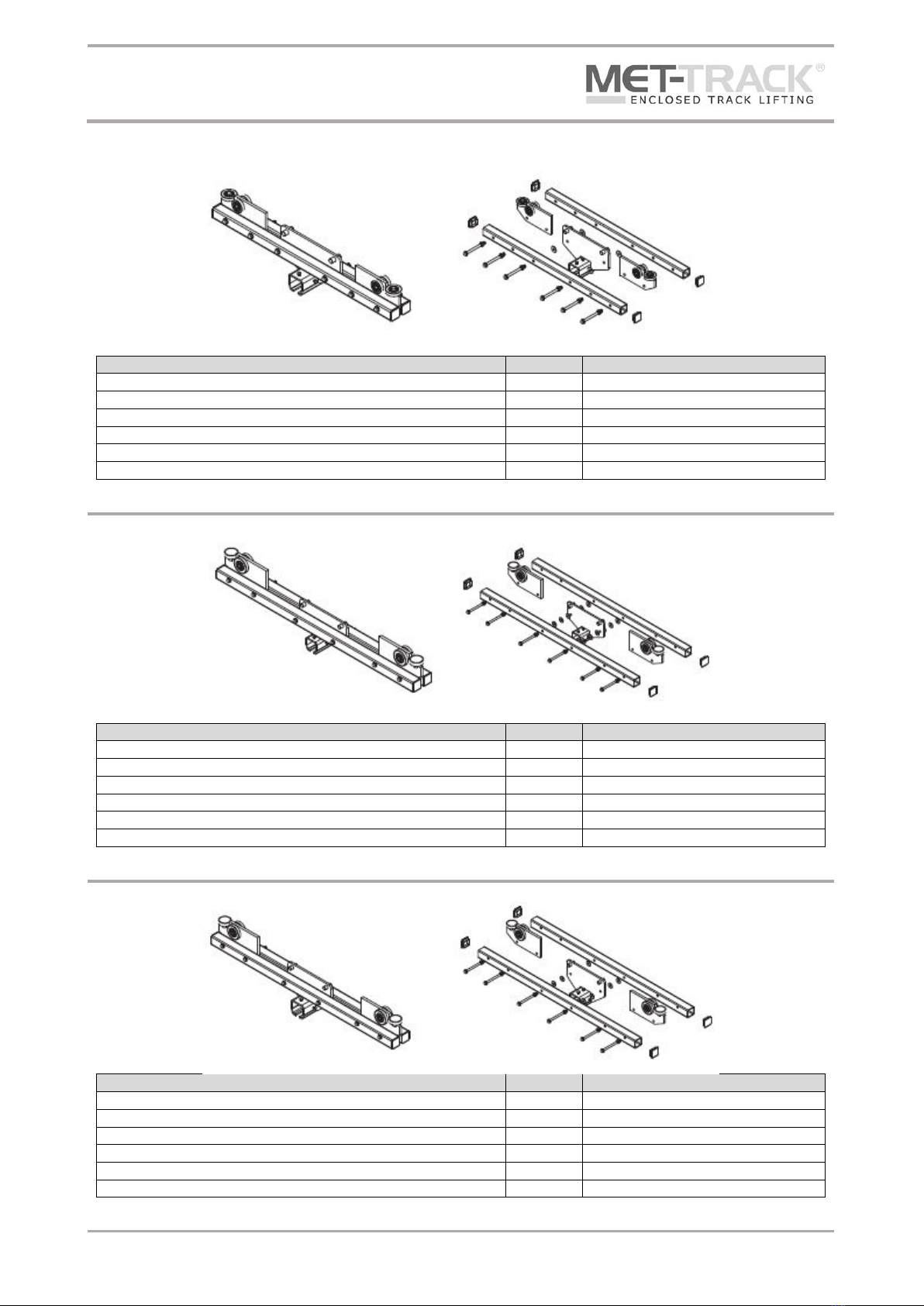
1554L-500 End Truck
Description
Qty
Part No.
400 Series Splice Plate Weldment
1
23618
Packer Plates for End Truck Designs
4
23629
Plastic End Cap
4
GPN 260 Q5050 5
Trolley for 600 Series Extended End Truck
2
23623
SHS for 1654-400 & 1654 End Trucks
2
23606
End Truck Fixing Kit 3
6
28036
1654L-400 End Truck
Description
Qty
Part No.
400 Series Splice Plate Weldment
1
23618
Packer Plates for End Truck Designs
4
23629
Plastic End Cap
4
GPN 260 Q 5050 5
Trolley for 500 Extended End Truck
2
23623
SHS for 1554-500 & 1554 End Trucks
2
23624
End Truck Fixing Kit 3
6
28036
1754L-400 End Truck
Description
Qty
Part No.
Truck Plate Weldment for 1754-400 End Truck
1
28029
Packer Plates for End Truck Designs
16
23629
Plastic End Cap
4
GPN 260 Q 6060 5
Trolley for 700 Extended End Truck
2
23625
SHS for 700 Series Extended Trolley
2
23608
End Truck Fixing Kit 4
6
28037
Floor Mounted Workstation Bridge Crane
Installation & Maintenance Instructions
Document No. TD002-0618
Last Updated: 14 June 2018
Page 14 of 29
1654L-500 End Truck
Description
Qty
Part No.
500 Series Splice Plate Weldment
1
23619
Packer Plates for End Truck Designs
4
23629
Plastic End Cap
4
GPN 260 Q5050 5
600 Series End Truck
2
23624
SHS for 600 Series Extended Trolley
2
23607
End Truck Fixing Kit 3
6
28036
1754L-500 End Truck
Description
Qty
Part No.
500 Series Splice Plate Weldment
1
23619
Packer Plates for End Truck Designs
4
23629
600 Series End Truck
2
23624
SHS for 600 Series Extended Trolley
2
23607
Plastic End Cap
4
GPN 260 Q5050 5
End Truck Fixing Kit 3
6
28036
1754L-600 End Truck
Description
Qty
Part No.
600 Series Splice Plate Weldment
1
236120
Trolley for 700 Series Extended End Truck
2
23625
SHS for 700 Series Extended Trolley
2
23608
Plastic End Cap
4
GPN 260 Q6060 5
Packer Plates for End Truck Designs
8
23629
End Truck Fixing Kit 4
6
28037

Floor Mounted Workstation Bridge Crane
Installation & Maintenance Instructions
Document No. TD002-0618
Last Updated: 14 June 2018
Page 15 of 29
1854 End Truck
Description
Qty
Part No.
700/850 Series Splice Plate Weldment
1
23621
Trolley for 800 Series Extended End Truck
2
23626
Plastic End Cap
4
GPN 260 Q5050 5
SHS for 1854 End Truck
2
28033
End Truck Fixing Kit 4
6
28037
When building this End Truck, care must be taken to ensure all four pairs of running wheels are
in contact with the runway at all times.

Floor Mounted Workstation Bridge Crane
Installation & Maintenance Instructions
Document No. TD002-0618
Last Updated: 14 June 2018
Page 16 of 29
1) If a festoon system has been selected for this workstation crane then it may be necessary to put the
appropriate number of festoon trolleys, end clamps and festoon storage extension (FSE) on to one of
the runway’s prior to the bridge being installed. This depends upon where the power source is located,
ideally the end clamp of the festoon should be positioned as close to the power source as possible.
2) Slide the End Trucks over the end of the bridge (Refer to the General Arrangement Drawing for the
positional dimensions).
3) Using the bolts on the top of the sleeve of one of the End Trucks, clamp the bridge (if a conductor
system is being installed this should be the End Truck on the side where the powerfeed will be
positioned).
4) Remove or leave free the bolts on the sleeve of the other End Truck, see fig 10. (This is to allow for the
bridge to float taking up the slight deviation of the installed runways).
5) Install an End Stop to the end of the bridge opposite to the festooning (where appropriate) see fig 11.
Being careful not to allow the free End Truck to slip off, lift up the bridge and insert the end Trucks into
the open ends of the runways. If appropriate make sure the festooning end of the bridge is oriented
with the festoon or conductor system on the runway.
6) Slide End Truck into the runways and immediately install the End Stop Kit in the open ends of the
runway to prevent bridge from falling back out the system.

Floor Mounted Workstation Bridge Crane
Installation & Maintenance Instructions
Document No. TD002-0618
Last Updated: 14 June 2018
Page 17 of 29
Fixings Parts List
End Stop Kits
All fixings must be UNC
All fixings must be SAE Grade 5
400 Series
500 Series
600 Series
700 / 800 Series
1 x RB45 Sleeve
1 x RB45 Sleeve
1 x RB67 Sleeve
1 x RB67 Sleeve
2 x ½” x 3” Bolt
2 x ½” x 3.5” Bolt
2 x 5/8” x 4.5” Bolt
2 x 5/8” x 5” Bolt
2 x ½” NYLOC Nut
2 x ½” NYLOC Nut
2 x 5/8” NYLOC Nut
2 x 5/8” NYLOC Nut
4 x Type B ‘Narrow’ ½” Washer
4 x Type B ‘Narrow’ ½” Washer
4 x Type B ‘Narrow’ 5/8” Washer
4 x Type B ‘Narrow’ 5/8” Washer
7) Check the position of the bridge, there must be a minimum of 2” between the end of the bridge and the
column upright
8) Clean the inside of the bridge flanges with a clean, dry cloth to remove grit or debris
9) Run the bridge down the complete length of the runway to check for smooth travel. If the bridge
movements is not smooth, check the runways are level and parallel, check that the End Trucks are only
clamped on one side. Make sure the inside running faces of all profiles are clean and all debris has been
removed
Floor Mounted Workstation Bridge Crane
Installation & Maintenance Instructions
Document No. TD002-0618
Last Updated: 14 June 2018
Page 18 of 29
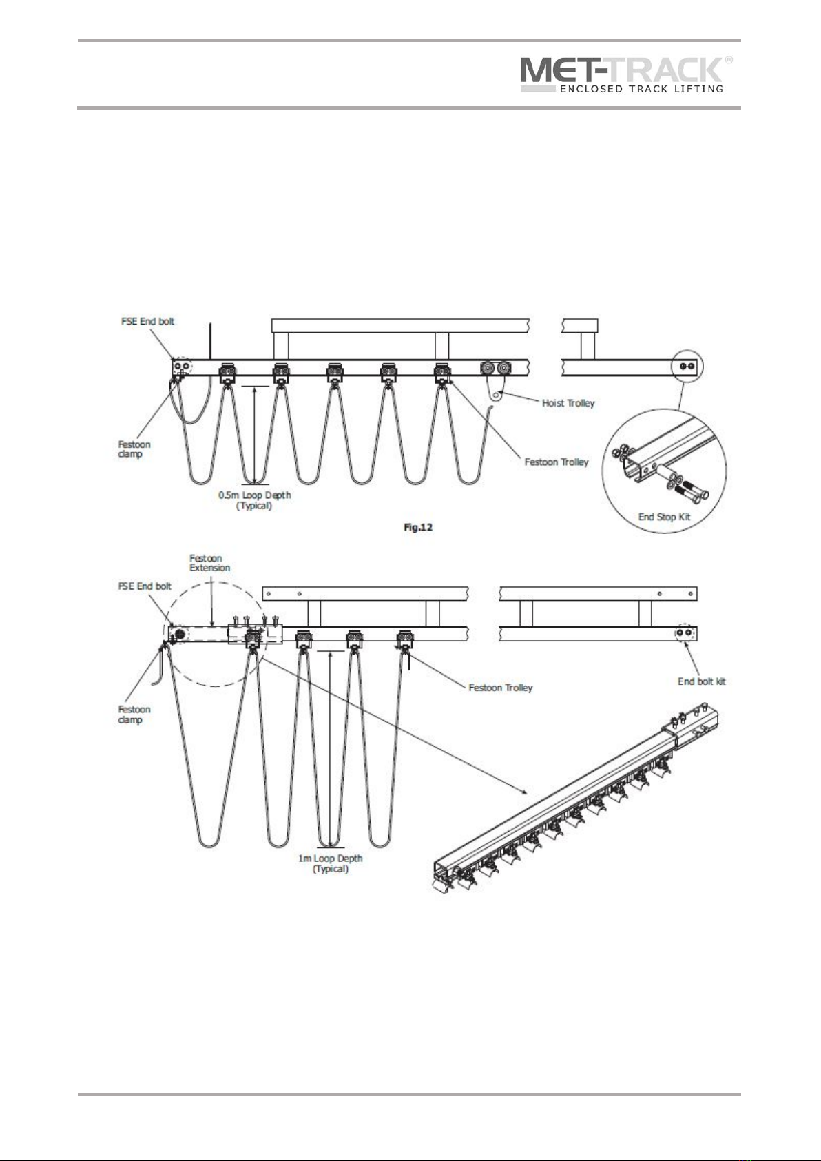
HOIST TROLLEY AND BRIDGE FESTOON INSTALLATION
Install hoist trolley and festoon trolleys on crane bridge track, if applicable, as shown in fig 12. Secure End
Stop bolts and rubber bumpers, also shown in fig 12. Install the festoon cable/hose on the festoon trolleys
at equal spacing, ensure festoon has correct loop depth (refer to the General Arrangement Drawing).
Once installation is completed, the bridge and runways should be levelled. The total system should then be
checked for tightness of all nuts and bolts.

Floor Mounted Workstation Bridge Crane
Installation & Maintenance Instructions
Document No. TD002-0618
Last Updated: 14 June 2018
Page 19 of 29
FESTOON STORAGE EXTENSIONS (FSE)
400 Series Festoon Extension
(Must be welded to the runway – refer to the General Arrangement Drawing)
500 Series Festoon Extension
600 Series Festoon Extension

Floor Mounted Workstation Bridge Crane
Installation & Maintenance Instructions
Document No. TD002-0618
Last Updated: 14 June 2018
Page 20 of 29
700 & 800 Series Festoon Extension
HOIST AND TROLLEY INSTALLATION
Attach hoist to hoist trolley. Use washers on host mounting pin to centre hoist inside hoist trolley. Reinstall
washer on outside of hoist trolley before installing or reinstalling cotter pin to secure hoist mounting pin.
Replace cotter pin if worn or broken. Bend cotter pin around mounting pin. See fig 13
WARNING: Do not operate hoist or crane if cotter pin is not in place and properly bent over. Check
regularly that the cotter pin is in place and securing the hoist on the hoist trolley.
Part No.
1418
1518
1618
1718
1818
Cap. (lbs)
250
500
1000
2000
4000
Other manuals for MET-TRACK
1
Table of contents
Other Metreel Construction Equipment manuals


Popular Construction Equipment manuals by other brands

Fayat
Fayat Bomag CR 820 T Tier 4 Operating instructions, maintenance instructions

Artic
Artic FUSION SPLICER 5.7 Operation manual

Bomag
Bomag BW 100 AD-5 Operating & maintenance instructions

MULTIQUIP
MULTIQUIP EM120 Operation and parts manual

Altrad
Altrad Belle BGN+ Operator's manual

Draper
Draper EC2000/PRO instructions


