Metreel ALULIFT Instruction Manual

Tel:
877 830-9803
Fax:
713 541-0530
Email:
sales@metreel.com
Website:
www.metreel.com
ALULIFT®Portable Aluminum Gantry Crane
Operation & Maintenance Instructions

Portable Aluminum Gantry Crane
Operation & Maintenance Instructions
Document No. TD005-0618
Last Updated: 21 June 2018
Page 2of 12
CONTENTS
Caution .............................................................................................................................................................3
Pre-Build Check List............................................................................................................................................4
Initial Set Up.................................................................................................................................................. 5-6
Assembly Instructions .................................................................................................................................... 6-8
Adjusting the Height...........................................................................................................................................9
Moving The Gantry Under Load.........................................................................................................................10
Maintenance Instructions..................................................................................................................................10
Parts List .........................................................................................................................................................11
Warranty.........................................................................................................................................................12

Portable Aluminum Gantry Crane
Operation & Maintenance Instructions
Document No. TD005-0618
Last Updated: 21 June 2018
Page 3of 12
IMPORTANT
Before assembly or operation of this gantry, please read these instructions carefully.
•ENSURE no parts are missing or damaged. A full list of required parts can be found on Page 10 of this
manual and a Pre-Build Check List is on Page 4
•DO NOT use to lift or support a person
•CHECK that the rated capacity is clearly marked on each side of the lifting beam
•DO NOT lift more that the rated capacity
•DO NOT adjust height whilst gantry is under load
•DO NOT push or pull unit with a forklift truck or other type of vehicle
•DO NOT allow the load to swing or roll against support members
•SECURE trolley and hoist in center of Beam when adjusting height
•BEFORE LIFTING ensure load is not attached to the floor, remove any obstacles that would
impede the lift
•CARE should be taken if it becomes necessary to move the gantry under load, we recommend that you
adhere to procedure for this operation, outlined in this manual

Portable Aluminum Gantry Crane
Operation & Maintenance Instructions
Document No. TD005-0618
Last Updated: 21 June 2018
Page 4of 12
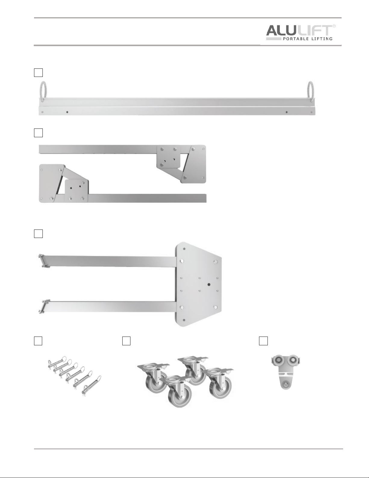
PRE-BUILD CHECK LIST
1 x Beam
2 x Upright Assemblies
2 x Leg Kits
6 x Loop Pins
4 x Wheel Assemblies
1 x Hoist Trolley

Portable Aluminum Gantry Crane
Operation & Maintenance Instructions
Document No. TD005-0618
Last Updated: 21 June 2018
Page 5of 12
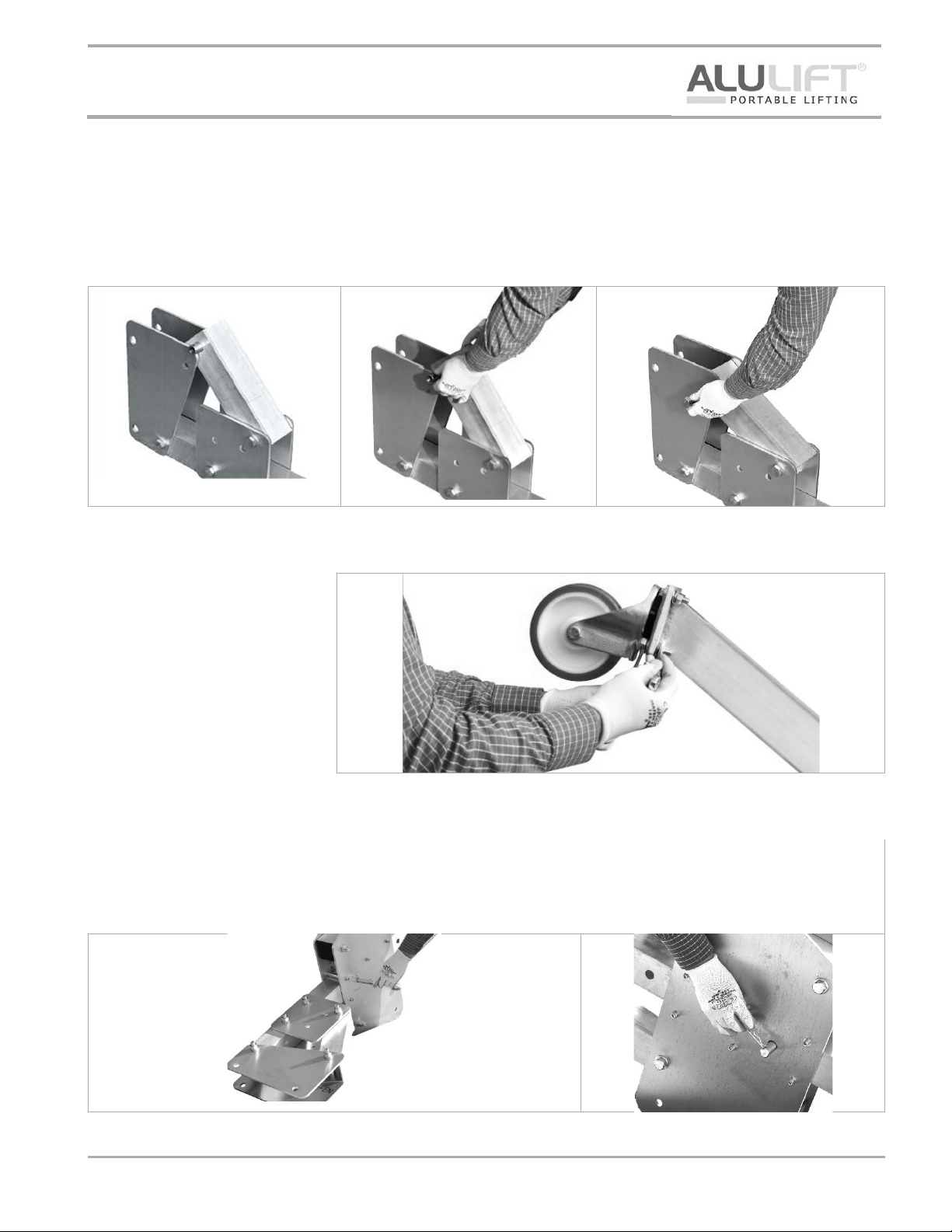
INITIAL SET UP (Should only have to be done once)
Building The A-Frame’s
Step 01
Place the Upright Assembly on the floor as shown in Fig 01
Al
ign the angled length to the bottom pre-drilled hole of the top plate as shown in Fig 02
Bolt together using the supplied fixings as shown in Fig 03
Fig 01
Fig 02
Fig 03
Step 02
Using the supplied fixing, attach
the Castors to the bottom of each
leg ensuring that the brakes are
facing
outside as shown in Fig 04
Fig 04
Step 03
Turn the Leg Assembly onto it’s side to allow easy insertion of the Upright Assembly and pin together through the
top pre
-drilled hole using the supplied Loop Pins as shown in Fig 05
Ensure
the Pin is kept in place by using the supplied clip as shown in Fig 06
Fig 05
Fig 06

Portable Aluminum Gantry Crane
Operation & Maintenance Instructions
Document No. TD005-0618
Last Updated: 21 June 2018
Page 6of 12
ASSEMBLY INSTRUCTIONS
Before assembling the gantry, please ensure that there is no machinery or equipment which could impede the
assembly operation. ALL personnel should wear appropriate safety gear, such as hard hats, safety shoes and
gloves.
Step 01
Place the A-Frames on the floor with the
top plate facing to the side as shown in
Fig 07
.
Fully extend the legs on the A
-Frame
ready for use
.
Fig 07
Step 02
Locate one end of the Beam inside the top plate of the A-Frame as shown in Fig 08
At the
other end of the Beam slide the Hoist Trolley inside the track profile.
Fig 08
Step 03
Locate the opposite end of the Horizontal Lifting Beam inside the top plate of the A-Frame as shown in Fig 09 (As
per Step 02
– but opposite side)
Fig 09

Portable Aluminum Gantry Crane
Operation & Maintenance Instructions
Document No. TD005-0618
Last Updated: 21 June 2018
Page 7of 12
Step 04
Engage the brakes on both castors at the end opposite to the first lift as shown in Fig 10.
This is to ensure the A
-Frame will not move when raising the beam.
Fig 10
Step 05
With one person holding the beam, another person should raise the A-Frame slowly by wheeling the legs into the
upright position.
At a point of 90
◦to the beam, use the locking pin, shown in Fig 11
Engage
brakes on castors as shown in Fig 12

Portable Aluminum Gantry Crane
Operation & Maintenance Instructions
Document No. TD005-0618
Last Updated: 21 June 2018
Page 8of 12
Step 06
Release brakes on castors, Fig 13 and raise the other A-Frame similarly with one person holding the main beam,
whilst another person raises the A
-Frame slowly by wheeling the legs into the upright position.
At a point of 90
◦to the beam, use the locking pin, shown in Fig 14 to secure the A-Frame in it’s vertical position.
Engage
brakes on castors as shown in Fig 15
Fig 14
Fig 15
Fig 13

Portable Aluminum Gantry Crane
Operation & Maintenance Instructions
Document No. TD005-0618
Last Updated: 21 June 2018
Page 9of 12
ADJUSTING THE HEIGHT
First secure the trolley and hoist to one of the Gantry A-Frames, preventing movement along the Beam.
We advise that you should only raise/lower one end at a time and that you do not raise/lower more than 2 height
increments in any one movement.
To raise or lower the
beam, first ensure that the upright leg is held to prevent it from dropping. Release the
locking pin (as shown in
Fig 16) and raise or lower the leg until the next 1 or 2 holes align. Re-insert the locking
pin and secure. Repeat until the correct height has been achieved.

Portable Aluminum Gantry Crane
Operation & Maintenance Instructions
Document No. TD005-0618
Last Updated: 21 June 2018
Page 10 of 12
MOVING THE GANTRY UNDER LOAD
Under certain circumstances it is possible to use the gantry to transport the load. This should ONLY be carried out
if the ground towards the destination is level, sound surface and two or more people are present.
We would also advise that you follow this procedure when moving the gantry.
1. With Castor Brakes engaged, raise the load to just above ground level (Max. 6” clearance)
2. Secure the trolley and load to one end of the A-Frame
3. Release Castor Brakes
4. From the other end, drag the gantry slowly to your destination point
5. Engage Castor Brakes
6. You can now untie the load and reuse as required
MAINTENANCE INSTRUCTIONS
To ensure the safe operation of your gantry, periodically inspect it for bent, broken, damaged, corroded, cracked or
missing parts.
If replacements part are required, please supply the complete gantry model and serial number both of which can
be found on the aluminum plate fixed to one of the A-Frame bases. Please also identify from the parts list drawing
(page 11) which item is required.
The only item which requires regular maintenance is to check the tightness of bolts and to lubricate the casters
through the grease nipple provided.
Should the Castors require lubrication we recommend NLGI No. 1 or No. 2 grease to be used.
Safety instruction labels and part identification codes should be in a legible condition at all times. If these become
lost or damaged we would recommend that you contact your supplier and request new labels.

Portable Aluminum Gantry Crane
Operation & Maintenance Instructions
Document No. TD005-0618
Last Updated: 21 June 2018
Page 11 of 12
PARTS LIST & DRAWING
Parts List
1
Lifting Beam
2
Safe Working Load Plates
3
Top Plate
4
Upright Assembly
5
Leg Kit
6
Loop Pins
7
Hoist Trolley
8
Wheels (braked)

Portable Aluminum Gantry Crane
Operation & Maintenance Instructions
Document No. TD005-0618
Last Updated: 21 June 2018
Page 12 of 12
WARRANTY
The 10 year warranty covers
•Defects in equipment, material and workmanship
Metreel Inc. warrants its ALULIFT®Portable Gantry Crane product to be free from defects in material and
workmanship for a period of ten years commencing on the date of shipment to the first retail purchaser.
This warranty extends to non-wearable parts only, with the exception of the wheels supplied on the hoist trolley.
This warranty does not cover defective equipment or system failure caused by misuse, negligence, improper
installation / maintenance or equipment that has been in excess of its rates capacity or beyond its service factors. It
does not apply to equipment that has been altered without Metreel Inc.’s written authorization.
Written notice of any claimed system defect must be given to Metreel Inc.’s within thirty days of discovery. Metreel
Inc.’s obligation under this warranty is limited to the replacement or repair of Metreel Inc.’s products at the factory
or separate location approved by Metreel Inc. The purchaser is responsible for all freight and transportation costs
relating to equipment repair or replacement. Other than the above-mentioned warranty, Metreel Inc. will
not honor any other warranties – whether express, implied or statutory – and disclaims any
warranties of merchantability or fitness for a particular purpose. Metreel Inc. is not liable – under any
circumstances – for any indirect, incidental, or consequential damages including but not limited to
lost profits, increased operating costs or loss of production.
This warranty does not extend to components or accessories not manufactured by Metreel Inc. The purchaser’s
remedy for such components and accessories will be determined by the terms and conditions of any warranty
provided by the manufacturer of such components and accessories.
Table of contents
Other Metreel Construction Equipment manuals
Popular Construction Equipment manuals by other brands

NorthStar
NorthStar M11953E.1 Operator's manual

Spanco
Spanco E Series Assembly and maintenance instruction

Sealey
Sealey SSC900 instructions

Kemper
Kemper KHS Hygiene Flush Box PRO Installation and operating instructions

Halfen
Halfen DEHA HTA Assembly instructions

Clarke
Clarke CCM125P Operating & maintenance instructions