METREL MD 9055 User manual
METREL MD 9055
High performance multimeter
Hochleistungsmultimeter
MD 9055
User manual
Bedienungsanleitung
Version 1.1.8, Code no. 20753237

2
Distributor:
METREL d.d.
Ljubljanska cesta 77
1354 Horjul
Slovenia
e-mail: metrel@metrel.si
web site: http://www.metrel.si/
Metrel GmbH
Mess und Prüftechnik
Orchideenstrasse 24
90542 Eckental -Brand
Germany
E-mail: metrel@metrel.de
Internet: http://www.metrel.de/
Metrel UK Ltd.
Test & Measurement
Unit 16, 1st Qtr Business Park
Blenheim Road
Epsom
Surrey
KT19 9QN,
Great Britain
E-mail: info@metrel.co.uk
Internet: http://www.metrel.co.uk
© 2012 –2022 METREL
Mark on your equipment certifies that this equipment meets the requirements of the EC
(European Community) regulations concerning safety and electromagnetic compatibility.
No part of this publication may be reproduced or utilized in any form or by any means without
permission in writing from METREL.

MD 9055 Multimeter Contents
3
Contents
English
1. Safety ...................................................................................................................................... 4
2. Product Description................................................................................................................ 6
3. Operation................................................................................................................................ 7
4. Maintenance......................................................................................................................... 21
5. Specifications........................................................................................................................ 23
6. Limited warranty .................................................................................................................. 30
7. Service................................................................................................................................... 31
Deutsch
8. Sicherheit.............................................................................................................................. 32
9. Produktbeschreibung ........................................................................................................... 34
10. Bedienung............................................................................................................................. 35
11. Wartung................................................................................................................................ 50
12. Technische Daten ................................................................................................................. 52
13. Eingeschränkte Garantie ...................................................................................................... 60
14. Wartung................................................................................................................................ 61

MD 9055 Multimeter Safety
4
1. Safety
This manual contains information and warnings that must be followed for operating the meter
safely and maintaining the meter in a safe operating condition. If the meter is used in a manner
not specified by the manufacturer, the protection provided by the meter may be impaired.
Observe proper safety precautions when working with voltages above 30 Vrms, 42.4 Vpeak or
60 VDC. These voltage levels pose a potential shock hazard to the user. Do not expose this
product to rain or moisture. The meter is intended only for indoor use.
Keep your hands/fingers behind the hand/finger barriers (of the meter and the test probe
assembly, where applicable) that indicate the limits of safe access of the hand-held parts during
measurements. Inspect lead wires, connectors, and probes for damaged insulation or exposed
metal periodically. If any defects are found, replace them immediately. Only use the test probe
assembly provided with the meter or a UL Listed test probe assembly to the same meter ratings
or better.
Optional offer premium test probe assembly using silicone lead wire insulation, at agent’s
discretion, is equipped with white inner insulation layers as wear indicators. Replace them
immediately if any of the white layers has become visible.
Disconnect the test leads from the test points before changing functions.
The meter meets IEC/EN/BSEN/CSA_C22.2_No./UL standards of 61010-1 Ed. 3.0, 61010-2-030
Ed. 1.0, 61010-2-033 Ed. 1.0 to Measurement Categories CAT III 1000V and CAT IV 600V ac & dc.
The accompanied test probe assembly meets IEC/EN/BSEN/CSA_C22.2_No./UL standards of
61010-031 Ed. 2.0 to the same meter ratings or better. The 61010-031 requires exposed
conductive test probe tips to be ≤4mm for CAT III & CAT IV ratings. Refer to the category
markings on your probe assemblies as well as on the add-on accessories (like detachable Caps
or Alligator Clips), if any, for applicable rating changes.
EUROPEAN DIRECTIVES AND UK STATUTORY REQUIREMENTS
The instruments conform to EUROPEAN (CE) Low-Voltage Directive 2014/35/EU,
Electromagnetic Compatibility Directive 2014/30/EU, and RoHS 2 Directive 2011/65/EU plus
amendment Directive (EU) 2015/863. The instruments also conform to the UK (UKCA) Electrical
Equipment (Safety) Regulations 2016, Electromagnetic Compatibility Regulations 2016, and The
Restriction of the Use of Certain Hazardous Substances in Electrical and Electronic Equipment
Regulations 2012.
TERMS IN THIS MANUAL
WARNING identifies conditions and actions that could result in serious injury or even death
to the user.
CAUTION identifies conditions and actions that could cause damage or malfunction in the
instrument.

MD 9055 Multimeter Safety
5
International symbols
Marking of Electrical and Electronic Equipment (EEE). Do not dispose of this
product as unsorted municipal waste. Contact a qualified recycler.
Refer to the explanation in this Manual.
Possibility of electric shock.
Earth (Ground).
Meter protected throughout by Double Insulation or Reinforced insulation.
Fuse.
Direct Current (DC).
Alternating Current (AC).
3Three-phase Alternating Current.
Application around and removal from hazardous live conductors is permitted.
Brief Information on Measurement Categories
Measurement Category IV is applicable to test and measuring circuits connected at the source
of the building’s low-voltage MAINS installation. Examples are measurements on devices
installed before the main fuse or circuit breaker in the building installation.
Measurement Category III is applicable to test and measuring circuits connected to the
distribution part of the building’s low-voltage MAINS installation. Examples are measurements
on distribution boards (including secondary meters), circuit-breakers, cables, bus-bars, junction
boxes, switches, socket-outlets, stationary motors in the fixed installation, and equipment for
industrial use.
Measurement Category II is applicable to test and measuring circuits connected directly to
utilization points (socket outlets and similar points) of the low-voltage MAINS installation.
Examples are measurements on MAINS CIRCUITS of household appliances, portable tools and
similar equipment.

MD 9055 Multimeter Product Description
6
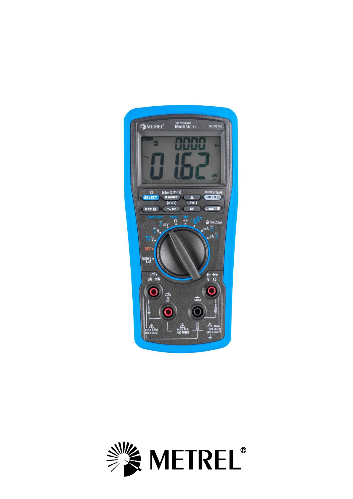
2. Product Description
This user's manual uses only representative model(s) for illustrations. Please refer detailed
specifications for function availability to each model.
1) 4-5/6 digits 60000 counts
display
2) Push-buttons for special
functions & features
3) Selector to turn the Power
On or Off and Select a
function
4) Positive Input Jack for T2
and mA/µA functions
5) Positive Input Jack for all
functions EXCEPT T2, A and
µA/mA
6) Common/ Negative
(Ground reference) Input Jack
for all functions EXCEPT T2
7) Positive Input Jack for A
function while Negative for T2
Analog bar-graph
The analog bar graph provides a visual indication of measurement like a traditional analog
meter needle. It is excellent in detecting faulty contacts, identifying potentiometer clicks, and
indicating signal spikes during adjustments.
MD 9055 Multimeter Operation
7
3. Operation
CAUTION: Before and after hazardous voltage measurements, test the voltage function on a
known source such as line voltage to determine proper meter functioning.
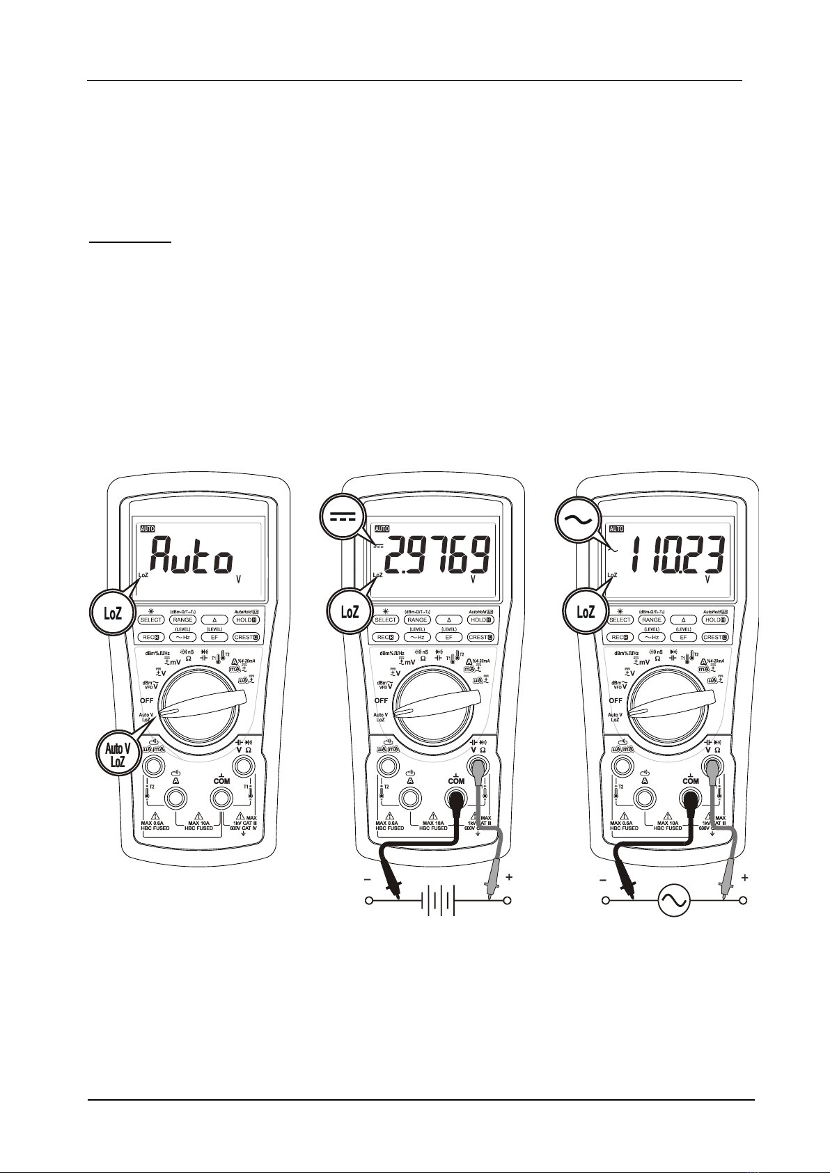
AutoV (LoZ)
Inputs are made via the test lead terminals V-COM. AutoV automatically selects measurement
function of DCV or ACV based on their input levels via the test leads. The input also provides a
low ramp-up impedance (LoZ) to drain ghost voltages.
•With no input, the meter displays “Auto” when it is ready.
•When a signal above the voltage threshold of 1V DC or AC up to the rated 1000V is
present, the meter displays the voltage value in appropriate DC or AC, whichever larger
in peak magnitude.
•Push-button features of only HOLD, AutoHold, EF and Backlight are available in AutoV
mode.
1) Ghost-voltage Buster: Ghost-voltages are unwanted stray signals coupled from adjacent
hard signals, which confuse common multimeter voltage measurements. The AutoV mode
provides low (ramp-up) input impedance (approx. 2.1kΩat low voltage) to drain ghost voltages
leaving mainly hard signal values on meter readings. It is an invaluable feature for precise
indication of hard signals, such as distinguishing between hot and open wires (to ground) in
electrical installation applications.
MD 9055 Multimeter Operation
8
2) AutoV Mode input impedance increases abruptly from initial 2.1kΩto a few hundred kΩ’s
on high voltage hard signals. “LoZ” displays on the LCD to remind the users of being in such a
low impedance mode. Peak initial load current, while probing 1000VAC for example, can be up
to 673mA (1000V x 1.414 / 2.1kΩ), decreasing abruptly to approx. 2.1mA (1000V x 1.414 /
670kΩ) within a fraction of a second. Do not use AutoV mode on circuits that could be
damaged by such low input impedance. Instead, use rotary selector or high input
impedance voltage modes to minimize the test loadings for such circuits.
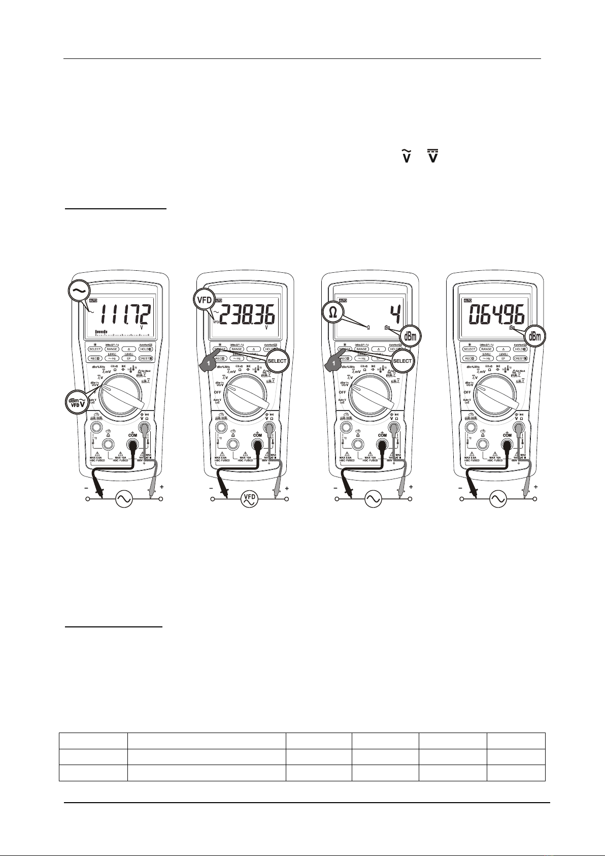
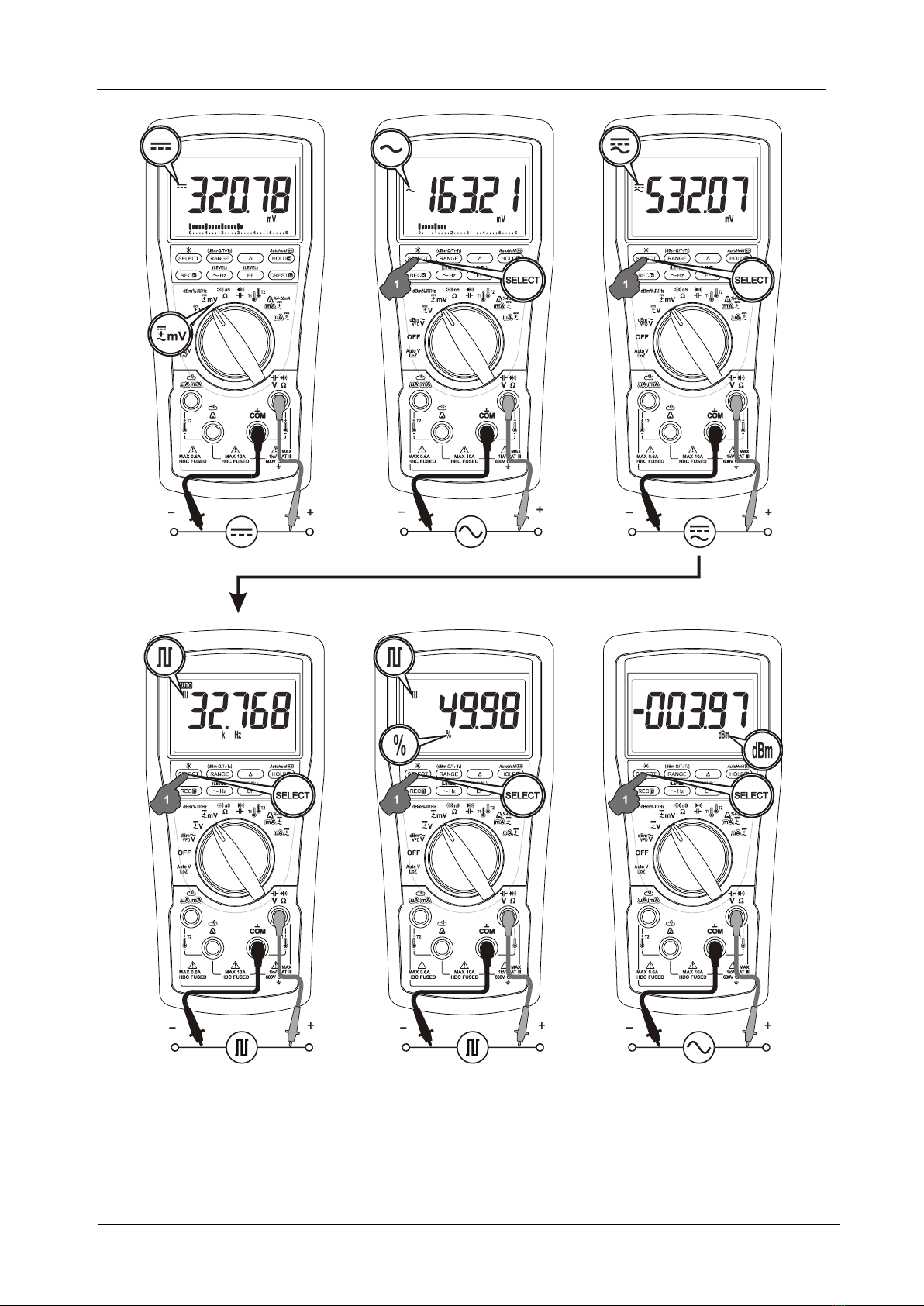
ACV; VFD-ACV; dBm
Inputs are made via the test lead terminals V-COM. Press the SELECT button momentarily to
select the subject functions in sequence. Last selection will be saved as power up default for
repeat measurement convenience.
In dBm function, power up default reference impedance will be displayed for 1 second before
displaying the dBm readings. Press dBm-(RANGE) button momentary to select different
reference impedance of 4, 8, 16, 32, 50, 75, 93, 110, 125, 135, 150, 200, 250, 300, 500, 600, 800,
900, 1000, up to 1200. Last selection will be saved as power up default for repeat
measurement convenience.
~Hz Line Frequency
Press the ~Hz button momentarily to switch to Line Frequency function. It is only available to
the functions as in the table below. Input sensitivity varies automatically with the function
range selected while the ~Hz function is being activated. Level 0 is the highest sensitivity while
LEVEL 3 is the lowest. Press momentarily the ~Hz (LEVEL) button to manually select the
available Trigger Levels (see table below) in sequence. Press the ~Hz button for one-second or
more to leave Line Frequency function.
TRIGGER
ACV/dBm/DCV/AC+DCV
VFD-ACV
A
mA
A
LEVEL 0
6V
600A
60mA
6A
LEVEL 1
60V
6000A
600mA
10A

MD 9055 Multimeter Operation
9
LEVEL 2
600V
600V
LEVEL 3
1000V
1000V
Note: It is recommended to directly measure the signals (voltage or current) in auto-ranging
mode before activating the ~Hz function in that same range to get the most appropriate trigger
level automatically. If the ~Hz reading is unstable, select lower sensitivity to avoid possible
electrical noises. If the reading shows zero, select higher sensitivity to measure.
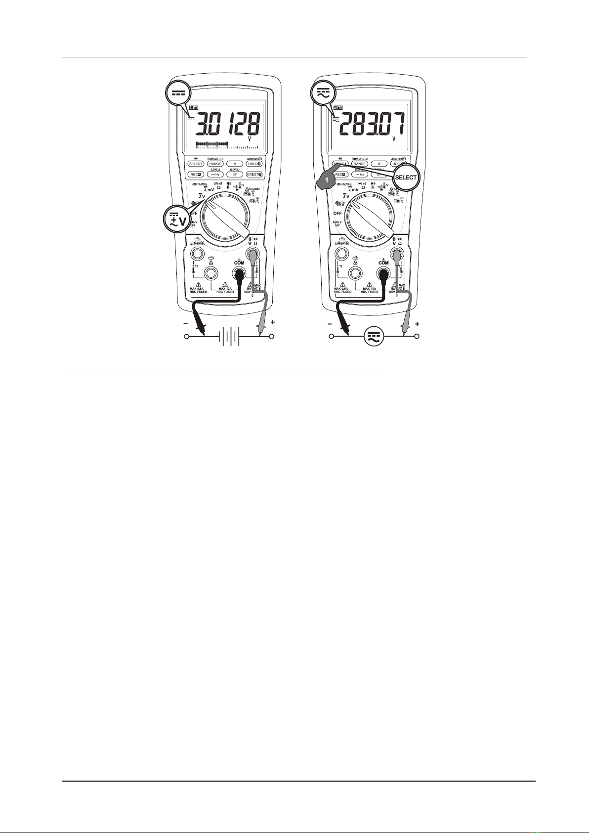
DCV; DC+ACV
Inputs are made via the test lead terminals V-COM. Press the SELECT button momentarily to
select the subject functions in sequence. Last selection will be saved as power up default for
repeat measurement convenience.
MD 9055 Multimeter Operation
10
DCmV; ACmV; DC+ACmV; Logic-level Hz; Logic-level Duty %; dBm
Inputs are made via the test lead terminals V-COM. Press the SELECT button momentarily to
select the subject functions in sequence. Last selection will be saved as power up default for
repeat measurement convenience.
MD 9055 Multimeter Operation
11
In dBm function, power up default reference impedance will be displayed for 1 second before
displaying the dBm readings. Press dBm-(RANGE) button momentary to select different
reference impedance of 4, 8, 16, 32, 50, 75, 93, 110, 125, 135, 150, 200, 250, 300, 500, 600, 800,
MD 9055 Multimeter Operation
12
900, 1000, up to 1200. Last selection will be saved as power up default for repeat
measurement convenience.
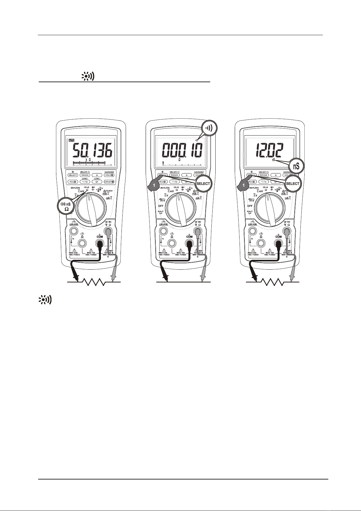
Resistance; BeepLitTM Continuity; nS Conductance
Inputs are made via the test lead terminals V-COM. Press the SELECT button momentarily to
select the subject functions in sequence. Last selection will be saved as power up default for
repeat measurement convenience.
BeepLitTM Continuity
This function improves convenience of checking wiring connections and operation of switches.
Resistance threshold is being used. A continuous beep tone together with display backlight
flashing indicate a complete wire. Audible and visible indications improve continuity readability
in noisy working environments.
nS Conductance
nS Conductance is the inverse of Resistance. That is: S=1/or nS=1/G. It virtually extends the
Resistance measurement range to the order of Giga Ohms for leakage measurements.
CAUTION: Using Resistance, BeepLitTM Continuity or nS Conductance function in a live circuit
will produce false results and may damage the meter. In many cases, the suspected
component(s) must be disconnected from the circuit to obtain an accurate measurement
reading.

MD 9055 Multimeter Operation
13
Capacitance; BeepLitTM Diode
Inputs are made via the test lead terminals V-COM. Press the SELECT button momentarily to
select thesubject functions in sequence. Last selection will be saved as power up default for
repeat measurement convenience.
BeepLitTM Diode
•Reading indication: Forward voltage drop (forward biased) for a good silicon diode is
between 0.400V to 0.900V. A higher reading indicates a leaky diode (defective). A zero
reading indicates a shorted diode (defective). An over-range display indicates an open
diode (defective). Reverse the test leads connections (reverse biased) across the diode.
The digital display shows over-range if the diode is good. Any other readings indicate
the diode is resistive or shorted (defective).
•Beep-Alert & BeepLitTM indication: When the display reading drops below 0.850V, the
meter will give a short beep to signal a reasonable forward voltage drop of common
diodes. However, if the reading further drops below 0.100V, the meter will give a
continuous beep tone together with flashing display backlight to indicate a shorted
diode or a complete wire. The function is similar to BeepLitTM Continuity function but
based on voltage threshold instead of resistance.
Note:
Discharge capacitor(s) before making capacitance measurements. Large value capacitors should
be discharged through an appropriate resistance load.
CAUTION: Using BeepLitTM Diode or Capacitance function in a live circuit will produce false
results and may damage the meter. In many cases, the suspected component(s) must be
disconnected from the circuit to obtain an accurate measurement reading.

MD 9055 Multimeter Operation
14
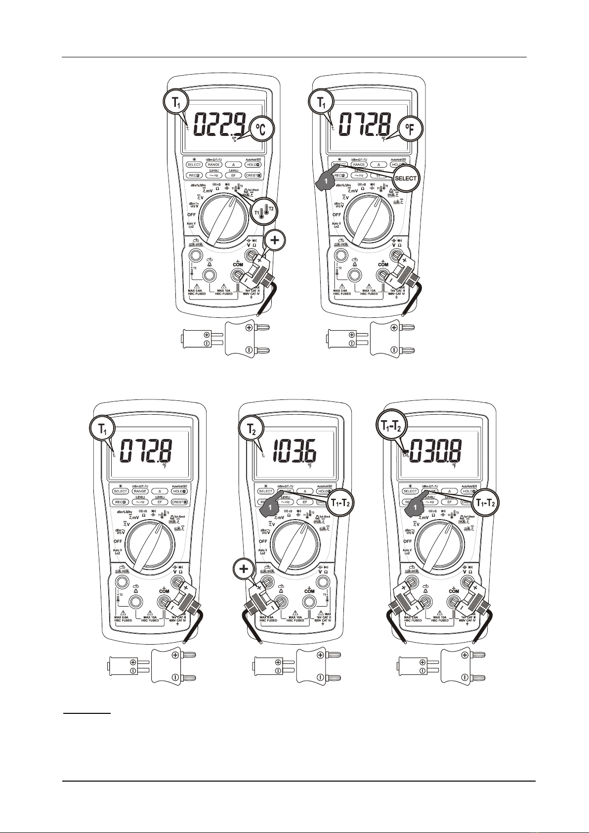
Temperature T1 & T2
T1 inputs are made via the input terminals V-COM. Press SELECT button momentarily can
toggle between °C (Celsius) and °F (Fahrenheit) readings when enabled. Last selection will be
saved as power up default for repeat measurement convenience. Additional T2 inputs are
made via the input terminals µA mA and A. Press RANGE (T1-T2) button momentarily to select
T1, T2 and T1-T2 in sequence.
Enabling °F and/or °C readings
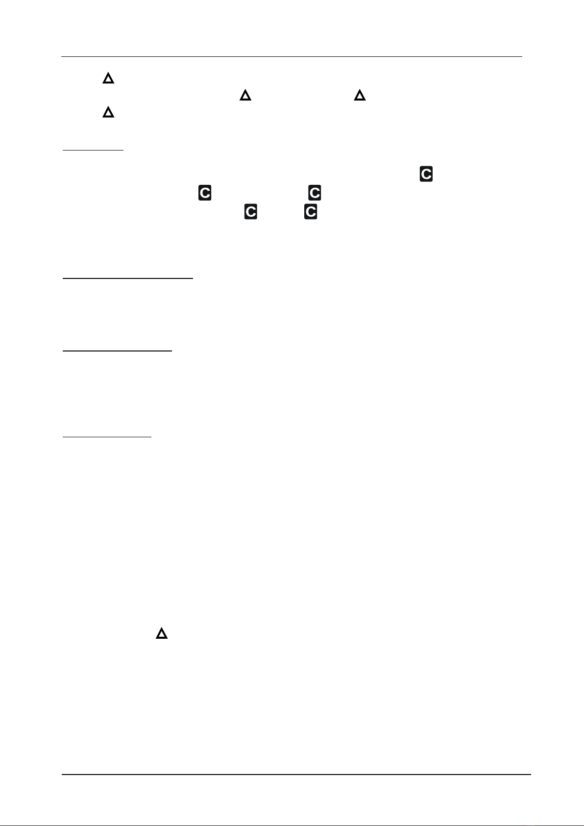
1) Enabling both °F and °C readings: Press-and-hold EF button to power on the meter. The
meter displays “C-F”to acknowledge both °F and °C readings are enabled.
2) Enabling °C readings only: Repeat step #1 when needed. Turn on the meter to temperature
function. Select readings in °Cand then turn the meter off. Press-and-hold CREST button to
power on the meter again. The meter displays “C”to acknowledge °C readings only is enabled.
3) Enabling °F readings only: Repeat step #1 when needed. Turn on the meter to temperature
function. Select readings in °Fand then turn the meter off. Press-and-hold CREST button to
power on the meter again. The meter displays “F”to acknowledge °F readings only is enabled.
Notes:
1) Temperature accuracies assume meter interior has the same temperature (isothermal stage)
of the ambient for a correct junction voltage compensation. Allow the meter and the type-K
probe set to reach isothermal stage in case of a significant change of ambient temperature. It
can take up to an hour for changes > 5°C.
CAUTION: Be careful of +/- polarities of the banana-plug when using the type-K temperature
bead-probe AMD 9023.
3) Banana-pins to type-K socket adapter AMD 9024 (optional purchase) can be used to adapt
other type-K probes with standard miniature plugs to MD 9055. However, the adapter becomes
part of the measurement isothermal block when in use and should be included in the overall
isothermal considerations to minimize erratic readings.
MD 9055 Multimeter Operation
15
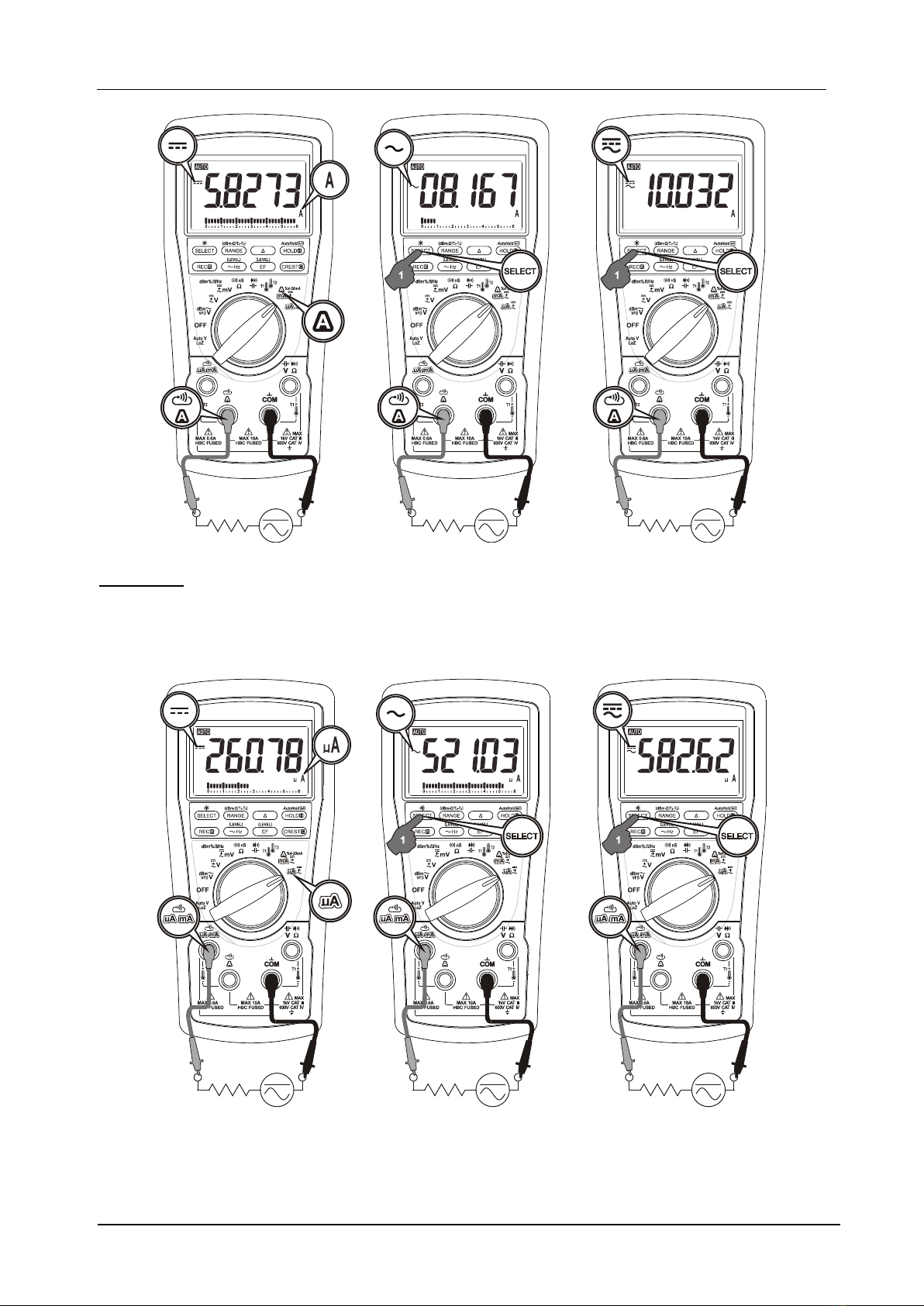
A Current
Inputs are made via the input terminals A–COM. Press the SELECT button momentarily to select
DC, AC,DC+AC in sequence. Last selection will be saved as power up default for repeat
measurement convenience of all current functions.
MD 9055 Multimeter Operation
16
µA Current
Inputs are made via the input terminals µAmA-COM. Press the SELECT button momentarily to
select DC, AC, DC+AC in sequence. Last selection will be saved as power up default for repeat
measurement convenience of all current functions.
MD 9055 Multimeter Operation
17
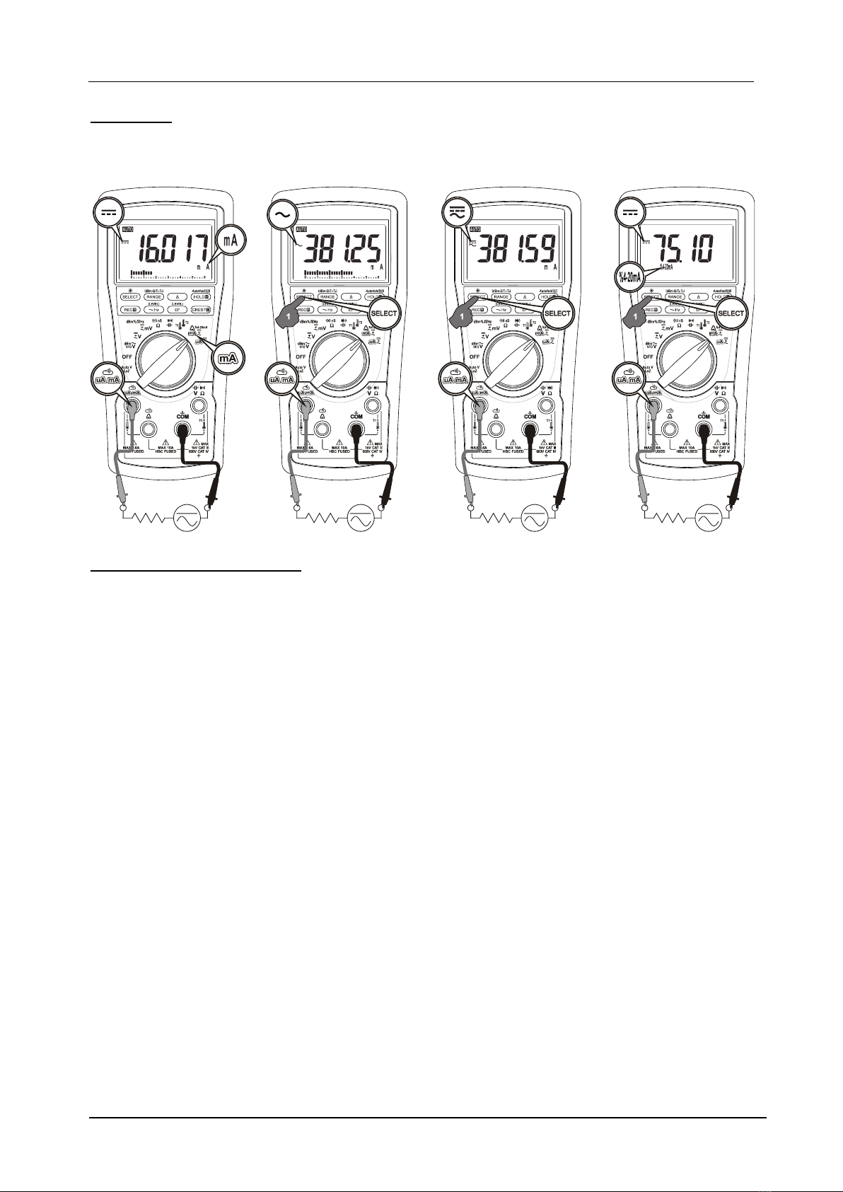
mA Current
Inputs are made via the input terminals µAmA-COM. Press the SELECT button momentarily to
select DC, AC, DC+AC and %4-20mA in sequence. Last selection will be saved as power up
default for repeat measurement convenience of all current functions.
Detection of Electric Field (EF)
Press EF button momentarily to enter EF Detection function. Default setting is high sensitivity:
EF-H. The meter displays “EF-H” when it is ready. If it is too sensitive for your application, press
EF button momentarily to select the lower sensitivity “EF-L”. The detected Electric Field
strength is indicated as a series of bar-graph segments on the display, plus variable beep tones.
Press EF button for one second or more to exit the EF Detection function.
Non-Contact EF Detection (NCV): An antenna is located at the top-right corner of the
instrument which detects the electric field surrounding energized conductors. It is ideal for
tracing live wiring connections, locating wiring breakages and to distinguish between live and
earth connections.
Probe-Contact EF-Detection (Single-pole): For more precise indication of live wires, such as
distinguishing between Live and Ground connections, use a single test probe to test via
terminal COM. Direct metal contact probing achieves the most distinctive indications.

MD 9055 Multimeter Operation
18
LCD Backlight
Press the SELECT button for one second or more to toggle the LCD backlight. The LCD backlight
goes off automatically after idling for approximately 16 minutes to extend battery life.
Manual or Auto-ranging
Functions are in auto-ranging by default (LCD “ ” is on). Press the RANGE button
momentarily to override and select manual-ranging. The meter will remain in the range it was
in, the LCD “ ” turns off. Press the button momentarily again to select the next range.
Press RANGE button for one second or more to resume auto-ranging.
Manual-ranging feature is not available to the Auto-V, dBm, Capacitance & Hz functions.

MD 9055 Multimeter Operation
19
HOLD
HOLD feature freezes the display for later view. LCD “ ” turns on. Press the HOLD button
momentarily to toggle the HOLD feature.
AutoHold Real-Read™
AutoHold feature displays the last latched stable reading when the test leads are removed from
the test points. It requires a significant measurement session. Real-Read™ shows real-time
readings during the significant measurement session to avoid “blind”measurements. Press the
AutoHold button for one-second-or-more to toggle the AutoHold feature on. LCD “ ”
turns on. Feature is available for functions: Resistance, Continuity, LoZ AutoV, VFD Volts,
Voltage and Current functions.
•Significant measurements (readings) are >5% of range in Voltage and Current functions,
or non-OL in Resistance function.
•Stable reading is a significant measurement with ≤30 counts difference from its two
immediate precedessors.
•Significant measurements are displayed in real time (Real-Read™); “- - - - -”is displayed
while awaiting significant-measurements.
•The AutoHold gives a short-beep with a flashing “ ” when a stable reading is
successfully latched and ready for later display. If any of the further significant-
measurement readings differs from the latched reading by >30 counts, the latched-
reading will be reset waiting to re-latch a new stable-reading.
•After a significant-measurement session, AutoHold gives a short-beep and displays the
latched-reading. The reading flashes to emphasize it is on hold to avoid confusions.
•The AutoHold gives 3 short-beeps and “- - - - -”flashes to indicate a null capture after a
significant-measurement. It means no stablereading is being latched or that has been a
reset to avoid displaying misleading readings after further encountering unstable signal
changes.
Note:Make sure both test probes are making good contacts simultaneously when using the
AutoHold feature. Single probe contact may lead to latching floating signal readings. Removing
both probes from the test points simultaneously largely avoids the mis-latching of an unwanted
floating signal.
MAX/MIN/AVG Record mode
Press REC button momentarily to activate MAX/MIN/AVG recording mode. LCD “MAX
AVG MIN”turn on. The meter beeps when new MAX (maximum) or MIN (minimum) reading is
updated. Press the button momentarily to read the MAX, MIN, AVG and MAXAVGMIN (active
measurement) readings in sequence. Press REC button for one second or more to exit this
mode. Auto-Power-Off is disabled automatically in this mode.
Relative mode
MD 9055 Multimeter Operation
20
Relative mode allows the user to offset the consecutive measurements with the current
reading as the reference value. LCD “ ” turns on. Press the button momentarily to toggle
Relative mode.
CREST mode
Press CREST button momentarily to activate CREST mode (Instantaneous PEAK-HOLD) to
capture current or voltage peak values in duration as short as 0.25ms. LCD & MAX turns on.
The meter beeps when new MAX (maximum) or MIN (minimum) reading is updated. Press
the button momentarily to toggle the MAX and MIN readings. Press the button for one
second or more to exit this mode. Auto-Power-Off is disabled automatically in this mode.
Availability: Voltage and Current functions.
Beep-Jack™ Input Warning
The meter beeps as well as displays “InEr” to warn the user against possible damage to the
meter due to improper connections to the A, mA, or A input jacks when another function,
especially a voltage function, is selected.
Auto-Power-Off (APO)
The Auto-Power-off (APO) mode turns the meter off automatically to extend battery life after
approximately 30 minutes of no rotary switch or push button operations. To wake up the meter
from APO, press the SELECT button momentarily and release, or turn the rotary switch OFF and
then back on. Always turn the rotary switch to the OFF position when the meter is not in use.
Power-on Options
•Disabling APO
Press-and-hold the SELECT button while powering on the meter can disable APO feature
temporarily during the power-on session. The LCD will display “dSAPO”to confirm selection
before the SELECT button is released.
•Disabling beep tone
Press-and-hold the RANGE button while powering on the meter can toggle the beep tone OFF
or ON in sequence. The meter confirms selection by displaying “dSbEP”for beeper OFF
(disabled) or “EnbEP”for beeper ON (enabled), before the RANGE button is released. Last
selection will be saved as power up default. When disabled, most operation beep tones are
turned off except those for BeepLitTM Continuity and BeepLitTM Diode functions.
•Shortening APO idling time for inspection
Press-and-hold the (Relative) button while powering on the meter can shorten the APO
idling time to approximately 8 seconds temporarily during the power-on session. It is designed
mainly for production inspection.
•Disabling/Enabling oC or oF function availability
See Temperature measurement operation description for details.
Table of contents
Languages:
Other METREL Multimeter manuals

METREL
METREL MD 9016 User manual

METREL
METREL MD 9035 User manual

METREL
METREL MD 9220 User manual

METREL
METREL MD 9010 User manual

METREL
METREL EurotestCOMBO MI 3125 User manual

METREL
METREL MD 9030 User manual

METREL
METREL MD 9880 User manual

METREL
METREL MI 3122 User manual

METREL
METREL MD 9020 User manual

METREL
METREL MD 9040 User manual


