Metric Halo 3d Upgrade Board Set User manual
MobileI/O
User’sGuide
3d Installation Guide
for ULN-8/LIO-8

ULN-8 3d Upgrade Installation Guide
Metric Halo
Revision: 1532
Publication date 2017-08-12 12:42:12 -0400 (Fri, 08 Dec 2017)
Copyright © 2017 Metric Halo

3
Table of Contents
1. ULN-8/LIO-8 3d Upgrade Installation Guide ................................................................................... 5
Introduction ............................................................................................................................. 5
Required Tools ......................................................................................................................... 5
Installation Kit Components ....................................................................................................... 7
Installation ............................................................................................................................. 10

4
List of Figures
1.1. #2 Phillips Head Screwdriver ...................................................................................................... 5
1.2. Nut Driver for DB25 Side Screws ................................................................................................ 6
1.3. Needlenose Pliers ...................................................................................................................... 6
1.4. (Optional) Power Screwdriver ..................................................................................................... 6
1.5. 3d Base Board with Pre-installed CPU Module, MH Clock Board, Rubber Feet on the bottom ........... 7
1.6. ULN-8/LIO-8 3d Back Panel ...................................................................................................... 7
1.7. Bridge Board ............................................................................................................................ 7
1.8. Foam Cap for Bridge Board ....................................................................................................... 8
1.9. AES Gasket Board .................................................................................................................... 8
1.10. 3d Upgrade Kit Matching Labels .............................................................................................. 9
1.11. Top Screw Placement ............................................................................................................ 10
1.12. Side Screw Placement, with Rack Ear ..................................................................................... 10
1.13. Side Screw Placement, No Rack Ear ....................................................................................... 10
1.14. Screws and Nuts to Remove from Back Panel .......................................................................... 11
1.15. Mic In Blank Plate ................................................................................................................ 11
1.16. AES/MIDI Board .................................................................................................................... 12
1.17. (a) AES/MIDI Board Pairing with Gasket Board ........................................................................ 13
1.18. (b) AES/MIDI Board Pairing with Gasket Board ........................................................................ 13
1.19. Detach Ribbon Cable ............................................................................................................ 14
1.20. Legacy Master Board and 2d Board ........................................................................................ 15
1.21. 3d Assembly Installed ........................................................................................................... 16
1.22. Bridge Board Installed ........................................................................................................... 17
1.23. Front Panel Meter Board Reconnected .................................................................................... 18
1.24. (a) AES/MIDI/Gasket Assembly Pin Alignment on 3d Base Board ................................................ 19
1.25. (b) AES/MIDI/Gasket Assembly Pin Alignment on 3d Base Board ............................................... 19
1.26. New Back Panel Placement ................................................................................................... 20
1.27. 3d Front Panel on Power Up ................................................................................................. 20
1.28. Screws and Nuts to Replace on Back Panel ............................................................................. 20
1.29. Foam Cap Applied to Bridge Board ........................................................................................ 21
1.30. Cap to Remove from Power Supply Board .............................................................................. 22
1.31. Cap Removed ....................................................................................................................... 22
1.32. Top Cover Replaced ............................................................................................................. 23

5
1. ULN-8/LIO-8 3d Upgrade Installation
Guide
Introduction
A video version of this guide is available here.
You will be working with electronic equipment so we strongly advise you to take the necessary steps to ground
yourself and to work in an environment with minimal static to avoid the potential for electrostatic discharge.
Please familiarize yourself with the parts and instructions before proceeding with installation.
Required Tools
You will need the following tools to do the installation:
• #2 Phillips Head Screwdriver
Figure 1.1: #2 Phillips Head Screwdriver

ULN-8/LIO-8 3d Upgrade Installation Guide
6
• Nut Driver size 3/16" OR Needlenose Pliers
Figure 1.2: Nut Driver for DB25 Side Screws
Figure 1.3: Needlenose Pliers
• (Optional) Power Screwdriver
Figure 1.4: (Optional) Power Screwdriver
If you choose to use a power screwdriver, set it to the lowest drive setting possible when replacing screws.
ULN-8/LIO-8 3d Upgrade Installation Guide
7
Installation Kit Components
The ULN-8/LIO-8 3d Upgrade Installation kit includes the following parts:
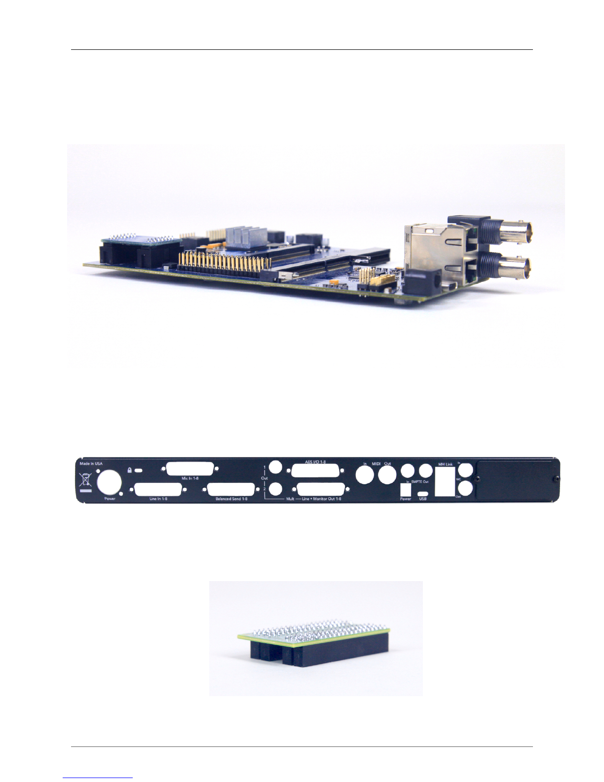
• 3d Upgrade Board Set
Figure 1.5: 3d Base Board with Pre-installed CPU
Module, MH Clock Board, Rubber Feet on the bottom
• New Back Panel
Figure 1.6: ULN-8/LIO-8 3d Back Panel
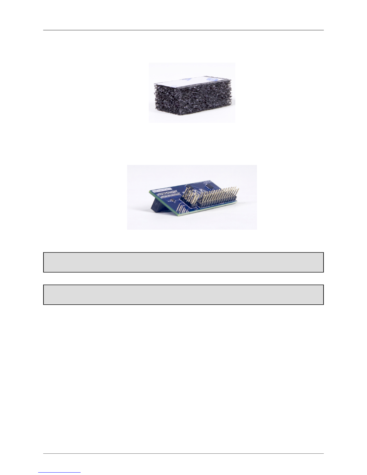
• Bridge Board
Figure 1.7: Bridge Board
ULN-8/LIO-8 3d Upgrade Installation Guide
8
• Foam Cap for Bridge Board
Figure 1.8: Foam Cap for Bridge Board
• AES Gasket Board
Figure 1.9: AES Gasket Board
Please familiarize yourself with the parts and instructions before opening your interface.
Be sure to discharge any static energy on your body before touching the interior of the interface.

ULN-8/LIO-8 3d Upgrade Installation Guide
9
Each individual upgrade kit has components that are uniquely serialized. Please upgrade one unit at
a time.
Make sure that the serial number on 3d card matches the serial number on your back panel.
Figure 1.10: 3d Upgrade Kit Matching Labels

ULN-8/LIO-8 3d Upgrade Installation Guide
10
Installation
1. Fully power off, disconnect power supply and all other connections to the unit.
2. Remove the six screws from the top of the case:
Figure 1.11: Top Screw Placement
3. Remove the screws from the left and right sides of the case. If the rack ears are fitted, keep their extra
screws separate from the other case screws. Please note that the screws on the rack ears are longer than
the others. Be sure to put the longer screws back in the rack ears when you reassemble the interface.
Figure 1.12: Side Screw Placement, with Rack Ear
If the rack ears are not fitted, there will be three screws per side.
Figure 1.13: Side Screw Placement, No Rack Ear
Remove the top cover.
ULN-8/LIO-8 3d Upgrade Installation Guide
11
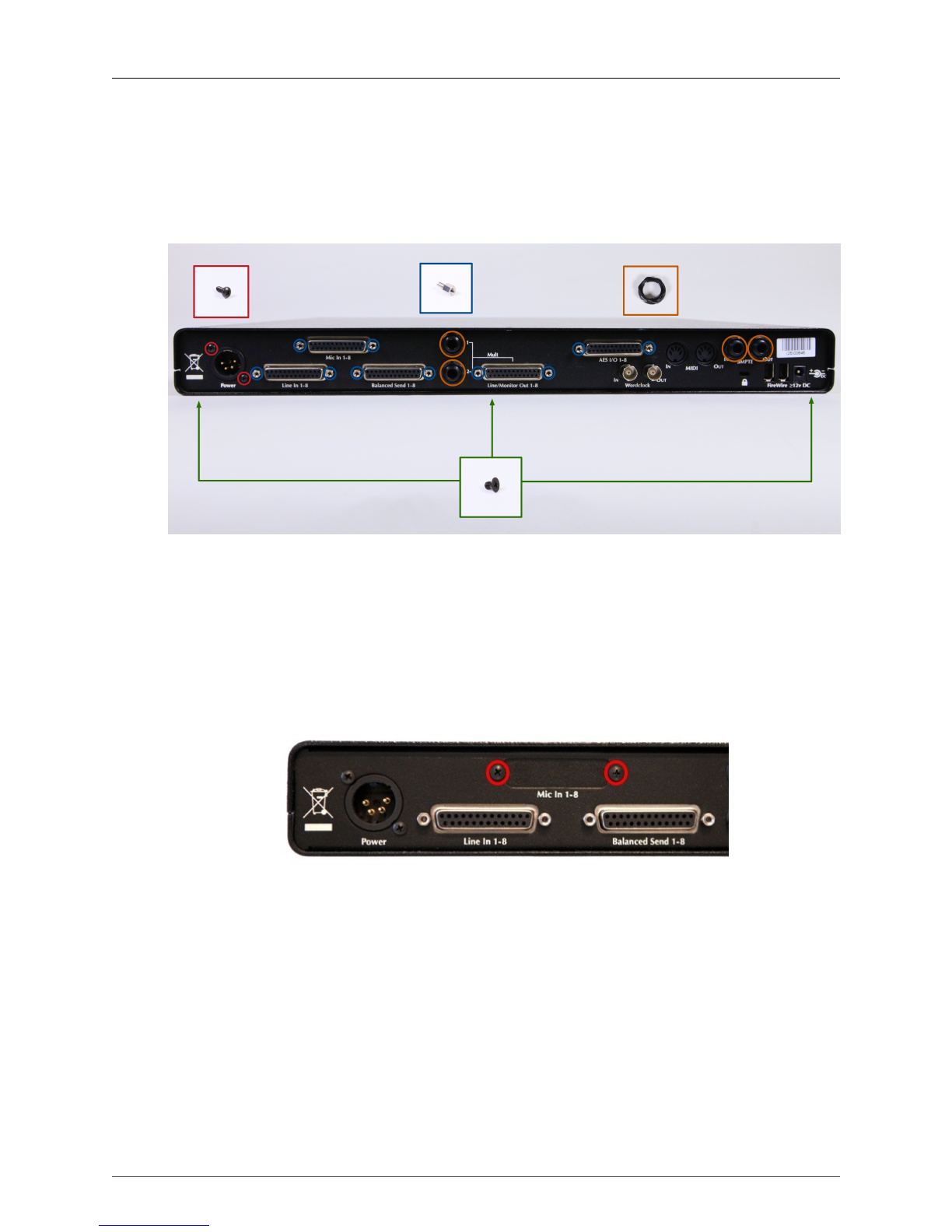
4. Remove the three screws directly underneath the back panel with a Phillips screwdriver.
Remove the two screws around the 4-pin XLR power connector with a Phillips screwdriver.
Remove the four ring nuts. This can typically be done by hand.
Using pliers or a nut driver tool, loosen and remove the 10 DB25 side screws.
Figure 1.14: Screws and Nuts to Remove from Back Panel
5. Slide off the old back panel and set it aside.
6. If upgrading a LIO-8, remove the two screws holding the Mic In cover plate, then remove the plate
and replace it over the same hole on the new back panel. If upgrading a ULN-8 or LIO-8 with mic
preamps, skip this step.
Figure 1.15: Mic In Blank Plate
ULN-8/LIO-8 3d Upgrade Installation Guide
12
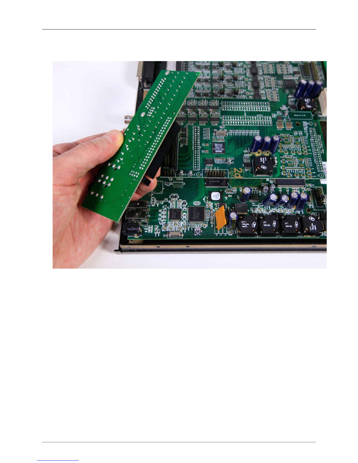
7. Remove the AES/MIDI board by pulling it up from the top of the 2d board.
Figure 1.16: AES/MIDI Board
ULN-8/LIO-8 3d Upgrade Installation Guide
13
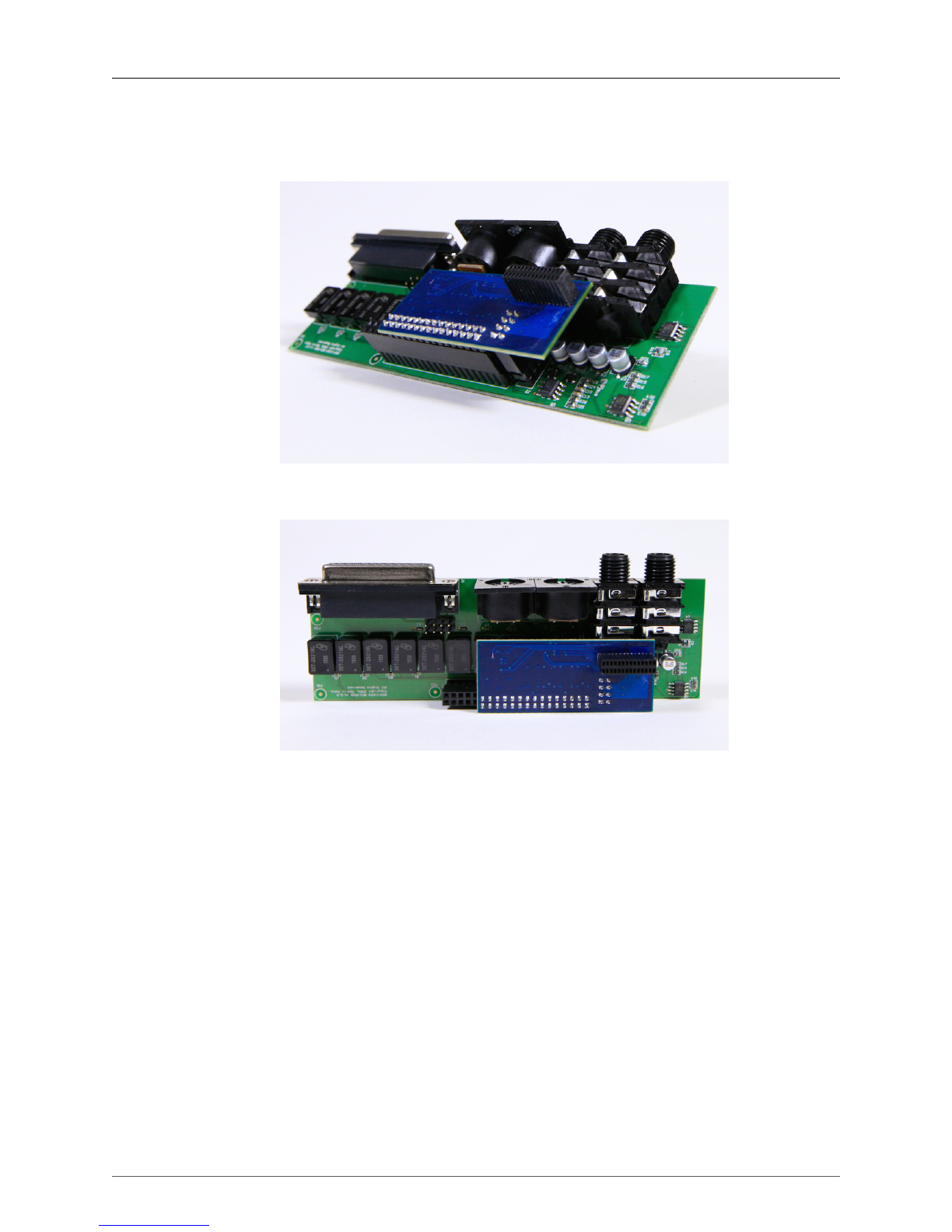
8. Mate the pins on the bottom of the AES MIDI board with the pins of the Gasket board. Set this board
cluster aside.
Figure 1.17: (a) AES/MIDI Board Pairing with Gasket Board
Figure 1.18: (b) AES/MIDI Board Pairing with Gasket Board

ULN-8/LIO-8 3d Upgrade Installation Guide
14
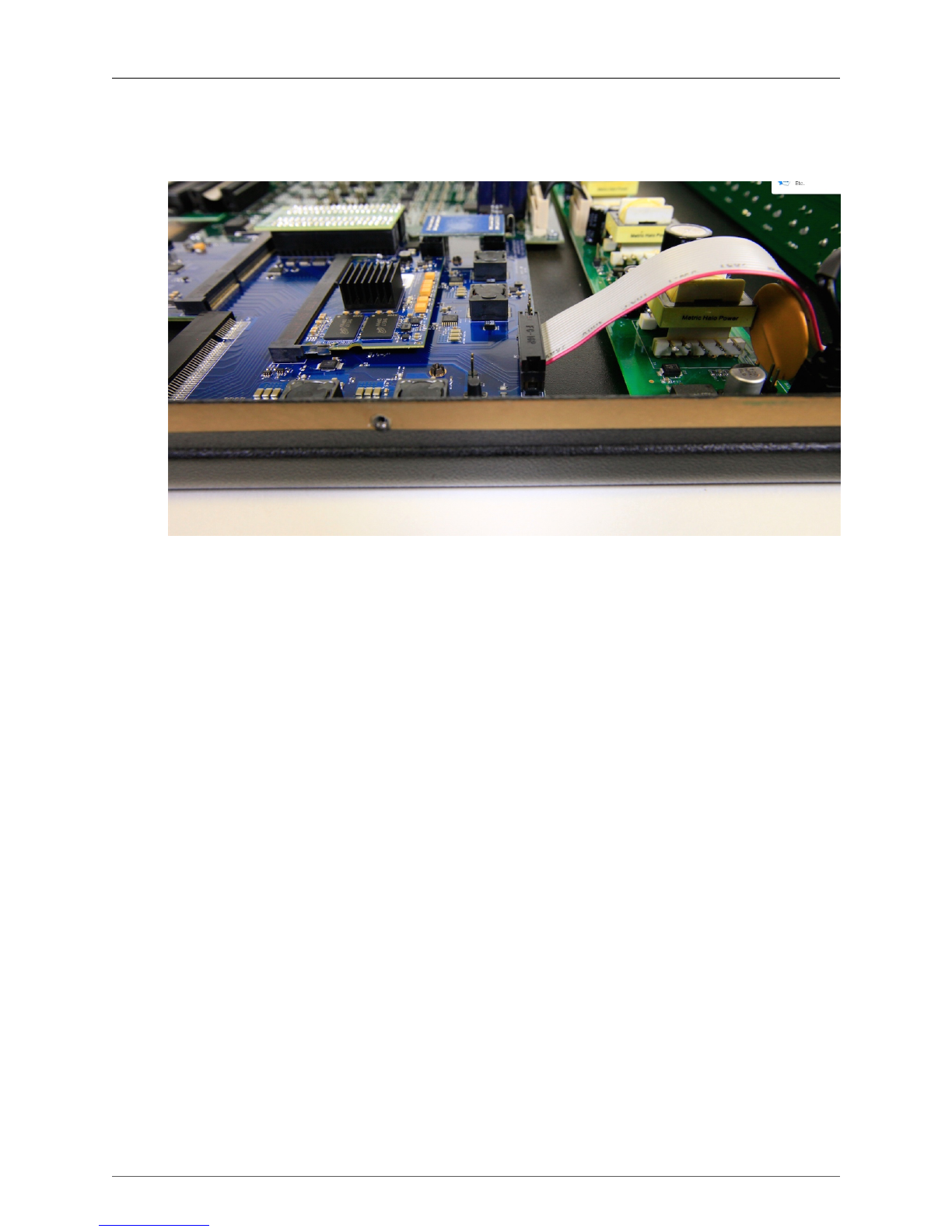
9. Detach the Ribbon cable connecting the master board to the front panel.
Figure 1.19: Detach Ribbon Cable

ULN-8/LIO-8 3d Upgrade Installation Guide
15
10. The Legacy master board and 2d board need to be removed from the unit. They may be removed
individually, or they might come out as a cluster. Rock the 2d board back and forth to loosen it from
the pins on the analog board, pulling upward. The master board may begin to pop off of the metal
posts on the bottom metal. Place a hand underneath the master board to pop it off the remaining posts.
Set the Legacy Master board and 2d card aside.
Figure 1.20: Legacy Master Board and 2d Board

ULN-8/LIO-8 3d Upgrade Installation Guide
16
11. Place down the 3d assembly, lining up the three holes in the 3d base board with the 3 posts in the
bottom metal. Press into place so the base board snaps down on all three posts. If there are rubber
feet present on the bottom metal that were supporting the original master board, peel them off if they
get in the way of the rubber feet under the 3d base board.
Figure 1.21: 3d Assembly Installed

ULN-8/LIO-8 3d Upgrade Installation Guide
17
12. Place down the bridge board with the extended lip pointing to the BACK of the unit. Very carefully
line up all pins on both the 3d base board and analog board with the bottom holes of the bridge board.
Once lined up, firmly press down.
Figure 1.22: Bridge Board Installed
IMPORTANT: The orientation and alignment of the bridge board is critical. The lip must be
facing toward the back of the unit. The bridge board needs to line up exactly, without any bent
or misaligned pins.
ULN-8/LIO-8 3d Upgrade Installation Guide
18
13. Reattach the ribbon cable from the meter board to the matching set of pins on the 3d board that sit
directly behind the ribbon cable coming from the meter board.
Figure 1.23: Front Panel Meter Board Reconnected

ULN-8/LIO-8 3d Upgrade Installation Guide
19
14. Install the AES/MIDI board with small section of pins of the attached gasket board lining up to the
matching connection on the 3d board.
Figure 1.24: (a) AES/MIDI/Gasket Assembly Pin Alignment on 3d Base Board
Figure 1.25: (b) AES/MIDI/Gasket Assembly Pin Alignment on 3d Base Board

ULN-8/LIO-8 3d Upgrade Installation Guide
20
15. Attach the new back panel, and replace three case screws on the bottom with a Phillips screwdriver.
Replace two DB25 side screws on either side of the AES DB25 connector with a nut driver tool.
Make sure the MH Link Ethernet stack is flush with its window on the back panel.
Figure 1.26: New Back Panel Placement
16. Attach the power supply, switch the unit on, and confirm that the front panel Power and Internal Clock
Source LEDs turn on.
The LED indications shown on power up indicate that the 3d installation is successful.
Figure 1.27: 3d Front Panel on Power Up
17. Switch the unit off and detach the power supply.
18. On the back panel, replace the remaining eight DB25 screws with the nut driver tool.
Replace two threaded Phillips head screws on either side of the 4-pin XLR power connector.
Replace the four ring nuts. These may be tightened by hand.
Figure 1.28: Screws and Nuts to Replace on Back Panel
Other manuals for 3d Upgrade Board Set
1
Table of contents


