Metrix 5534 User manual

5534/5535/5544/5545 SIGNAL CONDITIONER SENSORS
Installaon Manual
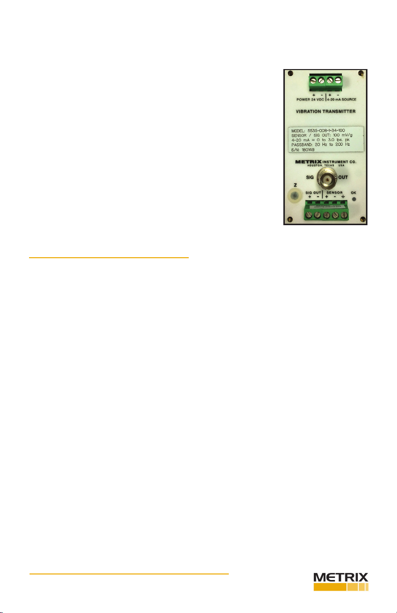
OVERVIEW
These Accelerometer Signal Condioners ac-
cept signals from machine casing mounted
Metrix Seismic Accelerometer or most
competve accelerometers and produce a
4-20 mA current source output proporonal
to the measured variable. The detecon
circuit is responsive to true RMS vibraon
but the output may be scaled either to peak
or RMS units. A green LED indicates sensor
and cable integrity. In the event of sensor
failure, the LED exnguishes and the output
current is driven below 3.6 mA, thereby
signaling a malfuncon. A BNC connector
gives access to the buered input signal for
local analysis. Oponal features for either
model include lters and galvanic isolaon
between input, output and power supply.
INSTALLATION
Each signal condioner is supplied with
either a at mounng base or a DIN rail
adapter. When mounng in the Metrix
Part #7595 explosionproof housing, the
DIN rail adapter version must be used. The
Metrix Part #7876 and Metrix Part #8172
weatherproof housings may be specied
for at base or DIN rail mounted signal
condioners. For the best results, the signal
condioner should be installed within 1000
feet (300 m) of the transducer.
WIRING
SENSOR (Signal Input): Connect the trans-
ducer or charge amp output cable leads
to these terminals. If the transducer is a
self-generang velocity pickup, polarity is
arbitrary unless the signal polarity at the SIG
Doc# M8687 • REV E July 2017
Doc# M8687 • REV E July 2017 Page 2 of 8
OUT BNC connector is important for analysis purposes. If an accelerometer, piezoelectric ve-
locity transducer or charge amp is used, correct polarity must be observed. The cable shield
should be wired to the terminal as follows:
4-20 mA (Current Source Output): Wire the receiving device to
these terminals, observing correct polarity. The total resistance of
the receiver input and wiring must be between 25 and 600 ohms.
SIG OUT (Signal Output): This signal is idencal to the input signal
and is buered for driving remote vibraon analysis instruments. The
terminal block terminals and the BNC connector are wired in parallel.
24 VDC (Power Input): For best results, the sum of the DC power
voltage, plus or minus AC ripple and noise, should be within 20 to 30
volts.
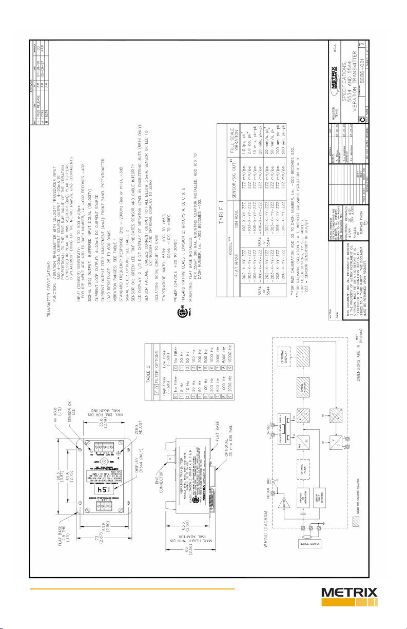
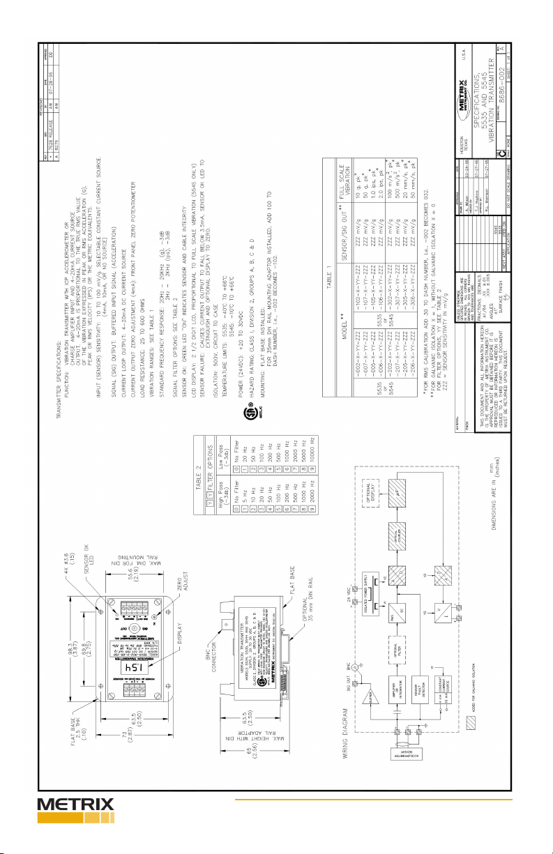
In Class I, Div. 2, Groups A, B, C & D locaons, the signal condioner
may be wired in accordance with page 4 or drawing 9031. Pages
6 and 7 show wiring diagrams for the 5534/5544 and 5535/5545,
respecvely.
INSTALLATION CONSIDERATIONS
Many variables exist in transmier installaons such as locaon, type of enclosure, proximity
and type of other devices, type and length of wiring, etc.
In general, the transmier should be located in a separate enclosure from electrical systems,
which switch electrical power at large voltages or currents, such as motor controls. Grounded
metal enclosures are muchpreferred to nonmetallic ones in areas where strong AC power or
radio frequency (RF) elds are present, even on an intermient basis. Possible sources of
electrical interference are electrical motors and generators, SCR drives, motor contactors, RF
heaters, engine ignion systems, handheld transceivers (walkie-talkies), cell phones, etc.
Handheld transceivers and cell phones are capable of interfering with the proper opera-
on of the transmier, especially with the enclosure door open and the device held in close
proximity to wiring. The RF ltering components in the transmier protect against normally
expected RF levels, but excessive levels can cause interference. It is good pracce to keep
operang RF sources as far away from electronic devices as possible. In severe cases a fer-
rite core (Metrix Part# 97007-006) may be required to be added on power or signal wiring.
These commonly available devices are either snapped over the wiring or the wiring is looped
several mes through the device.
In some installaons, the 24VDC power source can have signicant electrical noise present.
Common sources of noise are baery chargers, unregulated power supplies and switch-
ing type power supplies. 24VDC relays and solenoids that are not protected with snubbing
diodes or transient protectors will generate voltage transients that may interfere with the
proper operaon of the transmier. Ensure that the 24VDC power source is a regulated type
and free from electrical noise under all condions.
None of the wiring connected to the transmier or other devices within the enclosure
should be run in conduits or cable trays with plant power wiring or control relay and sole-
noid wiring. All inputs and outputs should be wired with shielded cables. Totally shielded
(100% foil) cables are preferred to 90% braided type shielded cables. The shield should be

Doc# M8687 • REV E July 2017 Page 3 of 8
connued to within 1 to 2 inches (25 to 50mm) of the transmier terminals. The shield itself
should be connected to the provided shield terminal. The shield connecon should be as
short as possible. Ensure that all shields are connected only at one end, preferably at the
transmier. Alternate shield connecons are possible such as to instrumentaon grounds,
etc. In general, connecon of shields to earth grounds should be avoided except at one cen-
tral earth grounding point for a complete system as “ground loops” may be created, which
can introduce unwanted power frequency pickup.
SENSOR MALFUNCTION
The signal condioners are provided with a sensor malfuncon detector, which causes the
output current to drop below 3.5 mA, the SENSOR OK LED to exnguish and the Display
(5544 & 5545 only) to read zero, in the event of an open circuit. The 5535 and 5545 also
detect incorrect polarity or shorted cable condions.
CALIBRATION
NULL OFFSET
The oset calibraon can be checked as follows:
Disconnect the transducer cable leads from the signal condioner and connect the following
in its place:
• Model 5534, 5544: Short circuit transducer connecons, except for -40X, -50X,
-60X and -70X (piezovelocity) units which require a resistor as specied for Models
5535 & 5545.
• Model 5535, 5545: Tie the transducer connecons together as follows:
4mA sensor current source condioners — 2.49K ohm resistor
10mA sensor current source condioners — 1K ohm resistor
No sensor current source condioners — short circuit
To adjust, remove the plasc plug from the Z (Zero) control and adjust the laer to obtain
exactly 4 mA output. Remove the short (or the resistor) and reconnect the transducer cable.
SPAN
The 20 mA output (SPAN) is factory set to the full scale value indicated on the nameplate
and is not eld adjustable. The most reliable way to check the calibraon of the sensor and
signal condioner as a system is to compare the indicated vibraon with an independent,
accurate vibraon measurement at the same locaon.
FORMULA: Measured mA - 4 mA
20 mA - 4 mA
EXAMPLE:
Measured mA Full Scale Vib Actual Vib
<3.5 1.0 ips, pk Sensor fault
4.0 1 .0 i p s , p k 0.0 ips, pk
12.0 1.0 ips, pk 0.5 ips, pk
20.0 1.0 ips, pk 1.0 ips, pk
STARTUP CURRENT
The signal condioners employ a DC-DC converter. As with all converters of this nature, a
large current spike occurs at startup. The current spike has a peak of 100 mA and lasts for
40 ms. Care should be exercised when wiring several units onto one supply. Power supplies
without adequate capacity will not allow the units to start properly. The internal power sup-
ply fuse may open as a result of this condion.

Doc# M8687 • REV E July 2017 Page 4 of 8

Doc# M8687 • REV E July 2017 Page 5 of 8
Doc# M8687 • REV E July 2017 Page 6 of 8
Doc# M8687 • REV E July 2017 Page 7 of 8

Doc# M8687 • REV E July 2017 Page 8 of 8
info@metrixvibraon.com
www.metrixvibraon.com
8824 Fallbrook Dr. Houston, TX 77064, USA
Tel: 1.281.940.1802 • Fax: 1.713.559.9421
Aer Hours (CST) Technical Assistance: 1.713.452.9703
This electronic equipment was manufactured according to high quality stan-
dards to ensure safe and reliable operaon when used as intended. Due to
its nature, this equipment may contain small quanes of substances known
to be hazardous to the environment or to human health if released into the
environment. For this reason, Waste Electrical and Electronic Equipment
(commonly known as WEEE) should never be disposed of in the public waste
stream. The “Crossed-Out Waste Bin” label axed to this product is a reminder
to dispose of this product in accordance with local WEEE regulaons. If you
have quesons about the disposal process, please contact Metrix Customer
Services.
ENVIRONMENTAL INFORMATION
This manual suits for next models
3
Table of contents


