User Guide
EdgeLens | INT10G8XX56 | 4.22.1
Port 13 Left Up Arrow Tap 3 Primary Inline Appliance Link LED
Port 14 Left Down Arrow Tap 3 Primary Inline Appliance Link LED
Port X Left Up Arrow Tap 3 Secondary Inline Appliance Link LED
Port X Left Down Arrow Tap 3 Secondary Inline Appliance Link LED
L/A7 Tap 4 Network Port 7 Link/Activity LED
L/A8 Tap 4 Network Port 8 Link/Activity LED
BP Tap 4 Bypass LED
Port 15 Left Up Arrow Tap 4 Primary Inline Appliance Link LED
Port 16 Left Down Arrow Tap 4 Primary Inline Appliance Link LED
Port X Left Up Arrow Tap 4 Secondary Inline Appliance Link LED
Port X Left Down Arrow Tap 4 Secondary Inline Appliance Link LED
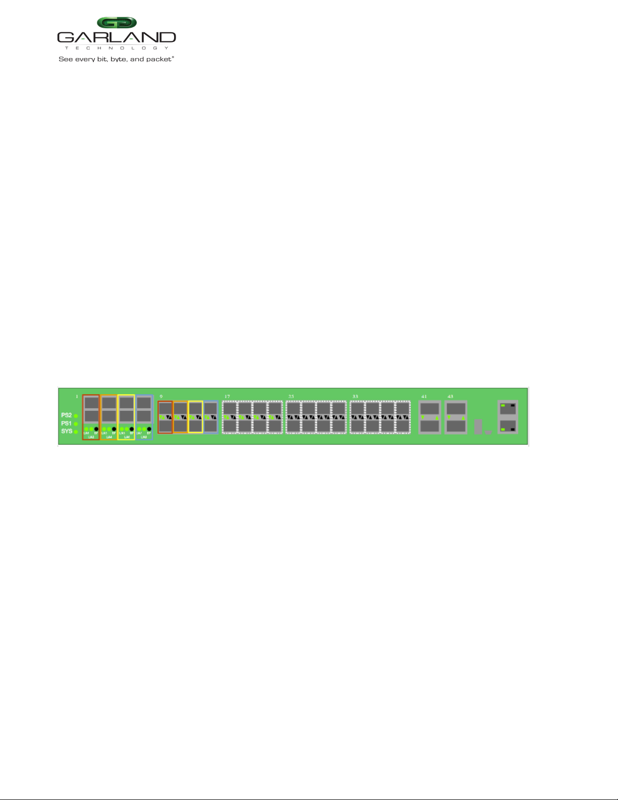
* The right up/down arrows for the primary inline appliance ports 9 through 16 as well as the secondary
inline appliance ports X are activity LEDs. These LEDs are N/A in the GUI.
* The L/A1 through L/A8 LEDs only indicate link in the GUI.
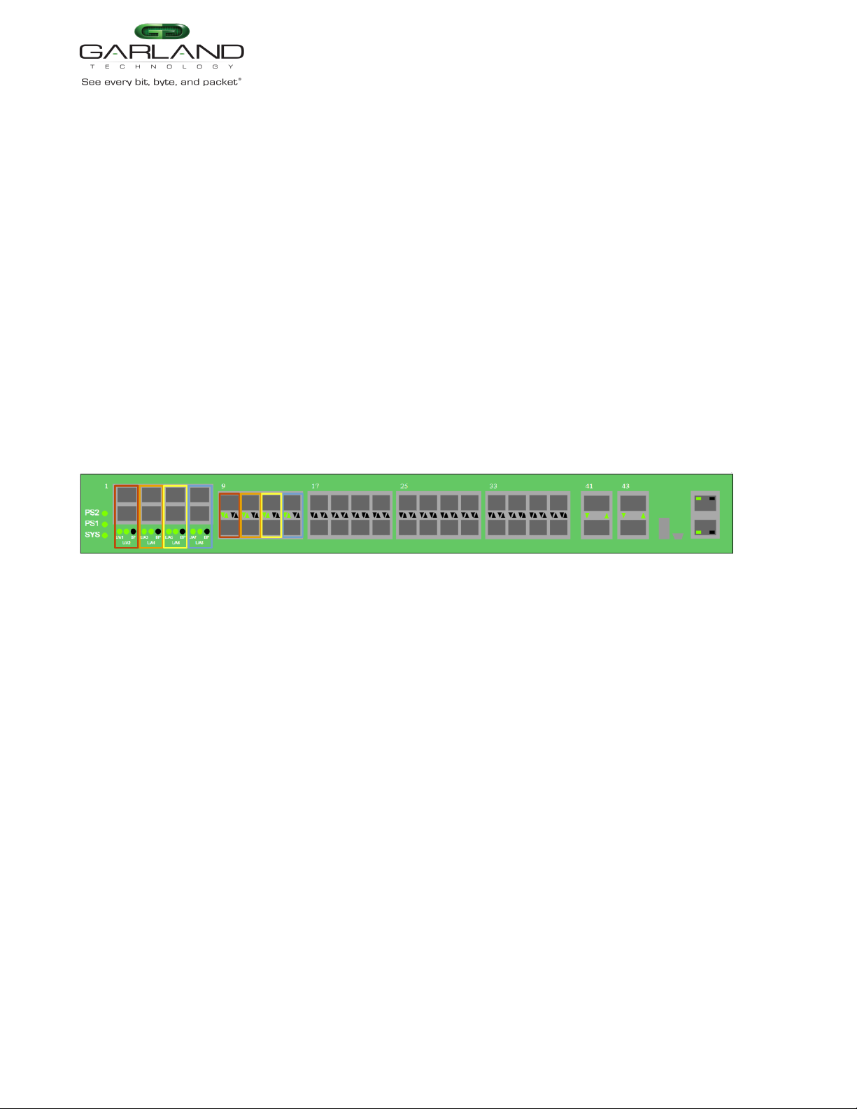
Load Balance Tap Mode
In this mode, the network ports and initial inline appliance ports are defined by the system for the tap.
Each tap may have up to three additional inline appliance ports applied, total 4. The ports will be
automatically configured by the system in the order assigned to the tap. The ports availability are
considered in vertical pairs, 17/18, 19/20, etc.
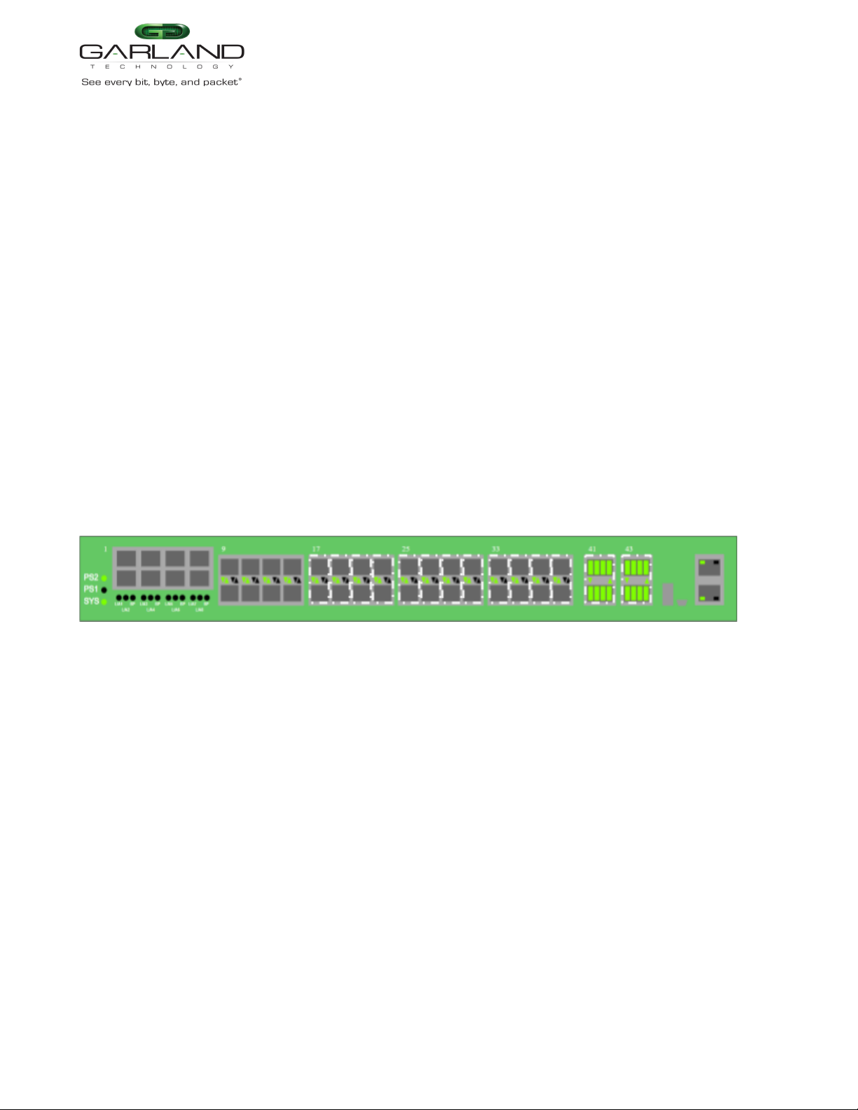
Dashboard Panel
LED Indications
L/A1 Tap 1 Network Port 1 Link/Activity LED
L/A2 Tap 1 Network Port 2 Link/Activity LED
BP Tap 1 Bypass LED
Port 9 Left Up Arrow Tap 1 Inline Appliance Link LED
Port 10 Left Down Arrow Tap 1 Inline Appliance Link LED
Port X Even Left Up Arrow Tap 1 Additional Inline Appliance 2 through 4 Link LED
Port X Odd Left Down Arrow Tap 1 Additional Inline Appliance 2 through 4 Link LED
L/A3 Tap 2 Network Port 3 Link/Activity LED
L/A4 Tap 2 Network Port 4 Link/Activity LED
BP Tap 2 Bypass LED
Port 11 Left Up Arrow Tap 2 Primary Inline Appliance Link LED
Port 12 Left Down Arrow Tap 2 Primary Inline Appliance Link LED
Port X Even Left Up Arrow Tap 2 Additional Inline Appliance 2 through 4 Link LED
Port X Odd Left Down Arrow Tap 2 Additional Inline Appliance 2 through 4 Link LED
L/A5 Tap 3 Network Port 5 Link/Activity LED
L/A6 Tap 3 Network Port 6 Link/Activity LED
BP Tap 3 Bypass LED
Port 13 Left Up Arrow Tap 3 Primary Inline Appliance Link LED
Port 14 Left Down Arrow Tap 3 Primary Inline Appliance Link LED
Garland Technology | 716.242.8500 | www.garlandtechnology.com
Copyright © 2022 Garland Technology, LLC. All rights reserved.
10