Metrix MX2033 User manual
Digital Proximity System
Installaon Manual
1180
Doc# 100545 • REV C (May 2016)
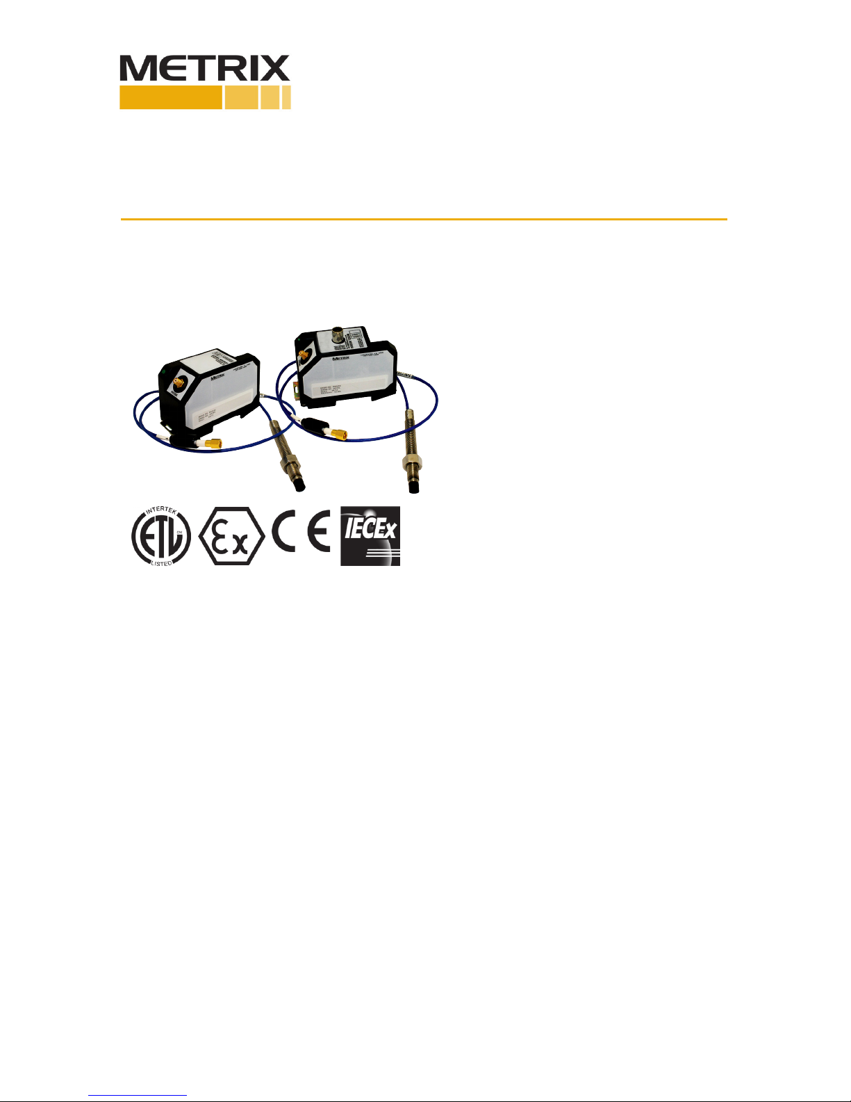
The DPS (Digital Proximity System) family
consists of two devices, the MX2033 and
MX2034. The MX2033 is a convenonal
3-wire driver while the MX2034 is a two-
wire current loop transmier. Users can con-
gure either unit to measure peak-to-peak
vibraon, gap distance, or rotaonal speed.
These products are used in conjuncon with
a proximity probe and extension cable to
measure the vibraon levels, gap distances,
or rotaonal speed of machinery shas.
Users can also congure the units via a USB
cable and conguraon soware.
Doc# 100545 • REV C (May 2016) Page 2 of 16
HIGH VOLTAGE
PRESENT
PROTECTIVE
EARTH NOTE
DANGER or
CAUTION
FUNCTIONAL
GROUND
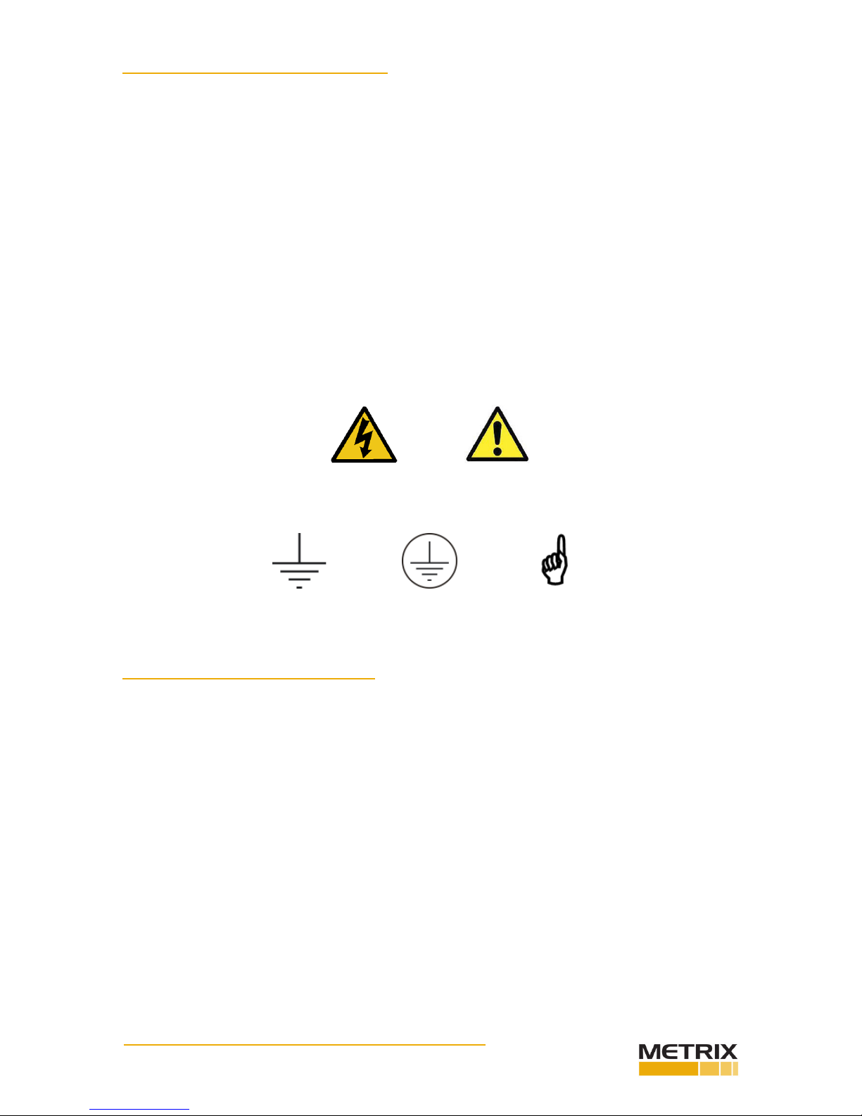
SAFETY TERMS AND SYMBOLS
Terms that appear in this manual requiring special aenon include:
• WARNING: Warning statements idenfy condions or pracces that could result in injury
or loss of life.
• CAUTION: Cauon statements idenfy condions or pracces that could result in dam-
age to the product, loss or corrupon of data, or damage to the environment or other
property.
• NOTE: Notes idenfy material of special interest or importance to the user, not including
cauons or warnings.
Symbols that may appear on the product and/or in this manual include:
GENERAL SAFETY SUMMARY
Review the following safety precauons to avoid injury and prevent damage to this product
or any products connected to it.
• USE ONLY AS SPECIFIED
To avoid potenal hazards, use this product only as specied. Only qualied personnel
should perform installaon and uninstallaon procedures.
• OBSERVE ALL TERMINAL RATINGS
To avoid re or shock hazard, observe all rangs and markings on the product. Consult
the individual secons of this manual for further rangs informaon before making con-
necons to the product.
• AVOID EXPOSURE TO CIRCUITRY
Do not touch exposed electrical connecons and components when power is present.
• DO NOT OPERATE WITH SUSPECT FAILURES
If you suspect there is damage to this product, have it inspected by qualied personnel.

Doc# 100545 • REV C (May 2016) Page 3 of 16
RECEIVING, INSPECTING AND HANDLING THE SYSTEM
Metrix ships the probe, extension cable, and driver as separate units that the user intercon-
nects at the installaon site. Carefully remove all equipment from the shipping containers
and inspect it for shipping damage. If you see shipping damage, le a claim with the carrier
and submit a copy to Metrix Instrument Co. Include part numbers and serial numbers on all
correspondence. If no damage is apparent and the equipment is not going to be used imme-
diately, return the equipment to the shipping containers and reseal unl ready for use. Store
the equipment in an environment that is free from potenally damaging condions such as
extreme temperature, excessive humidity, or a corrosive atmosphere.
OVERVIEW
The Metrix Digital Proximity System comes in two versions:
• MX2033 – 3-wire proximity driver
• MX2034 – 2-wire, loop-powered proximity transmier
The followings secons cover each of these in more detail.
MX2033 Three-Wire Proximity Driver
The MX2033 signal output is compable with industry-standard connuous-vibraon moni-
toring systems and is the format specied in API Standard 670. It uses -24VDC excitaon
and provides the output signal in mV/mm, typically 7.87 mV/mm (200mV/mil) for 5 mm and
8mm probes and 3.94 mV/mm (100 mV/mil) for 11 mm probes.
MX2034 Two-Wire Vibraon / Posion / Speed Transmier
The MX2034 signal format is for use when vibraon, axial posion, or rotaonal speed
measurements will be directly connected to a PLC, DCS, SCADA system, or other instrumen-
taon that accepts an ISA standard 4-20 mA signal, without the use of a separate monitor
system. It is powered by +24 VDC, supplied within the current loop. The device is user-pro-
grammable to funcon as either a radial vibraon transmier (where the 4-20 mA signal is
proporonal to peak-peak vibraon amplitude), as an axial posion transmier (where the
4-20 mA signal is proporonal to average probe gap) or as a rotaonal speed transmier
(where the 4-20mA signal is proporonal to sha speed). For convenience when connecng
to signal analyzers, portable data collectors, and test instrumentaon, the raw vibraon /
speed signal is available at a short-circuit protected BNC connector.
INSTALLATION
Probe Installaon
Mount the probe in a simple bracket, such as the Metrix Model 7646, in a tapped hole in
the bearing cap or by means of a Metrix Model 5499 Probe Housing. The laer arrangement
provides an easy means to adjust the probe air gap, especially where the target is some
distance from the outside surface of the machine.
When inserng the probe through the machine case or bearing cap, the signal voltage may
vary widely before the proper gap is obtained. Therefore, be sure the gap is within 0.07” (1.8
mm) of the target before aempng to set the gap electrically. If possible, set the probe gap
while the machine is shutdown, to avoid the danger of damaging the probe in the event that
it touches the sha.
Doc# 100545 • REV C (May 2016) Page 4 of 16
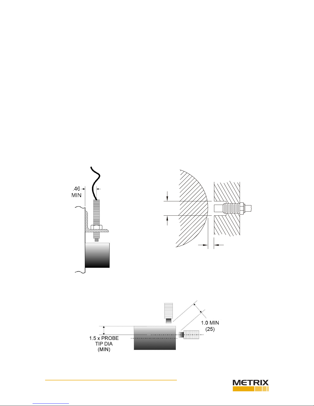
Figure 1: Clearance dimensions for standard 5mm and 8mm radial vibraon measurements.
(Tight View can be closer)
Figure 2: Minimum distance between probe ps.
(Tight View can be closer)
Connect the probe to the driver/transmier using the proper coax extension cable. If a con-
nector must be replaced, the overall length of the probe or extension cable can be reduced
by 2” total without adversely aecng the calibraon and linearity. Insulate the probe con-
nector/extension cable connector juncon with the Metrix 8973 connector insulator.
Radial vibraon measurements
For radial vibraon measurements, mount the probe perpendicular to the sha with the
probe p approximately 0.050” (1.25 mm) from the sha surface. Provide the probe p with
sucient clearance from surrounding metal to prevent an erroneous output. As a minimum,
the clearance diameter should be 0.75” (19 mm) for the full length of the probe p. See
Figure 1. You can set the probe gap “electrically” to the center of its measurement range by
observing the DC output voltage at the BNC connector on the MX2034 or the terminal block
connecon on the MX2032 / MX2033 with an isolated meter. Adjust the probe gap to obtain
-10 VDC, which corresponds to a gap of approximately 0.050” (1.25 mm). The preferred
stac gap range is 0.035” to 0.050”. This gap corresponds to a voltage of -7.0 VDC to -10
VDC. To prevent cross-feed between two probes mounted in the same vicinity, maintain a
minimum 1.0” (25 mm) spacing between the probe ps. See Figure 2.
0.75” (19 mm)
MIN
GAP

Doc# 100545 • REV C (May 2016) Page 5 of 16
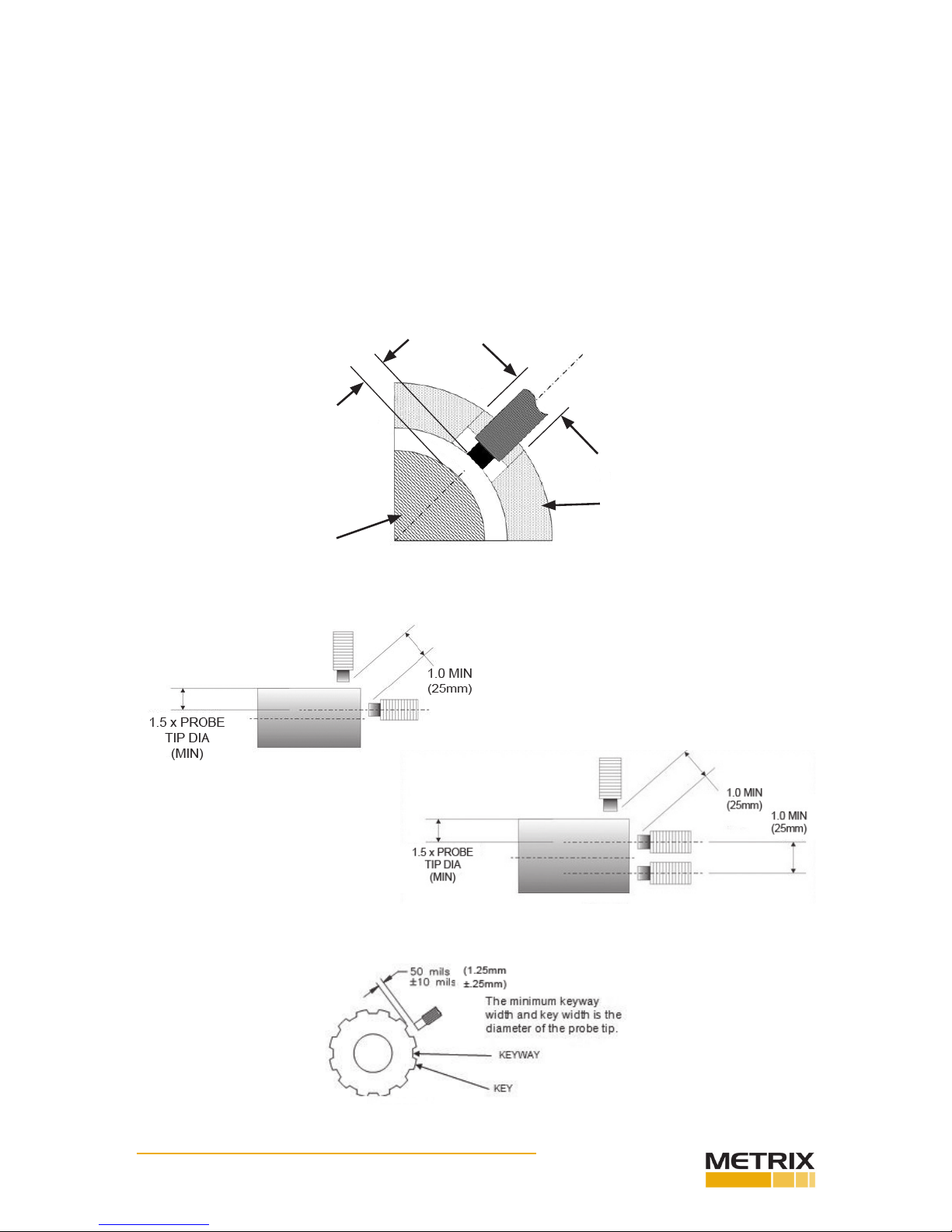
Figure 3: Key dimensions for thrust measurements
Thrust measurements
For thrust measurements ensure the thrust range is within the probe range. Move the ma-
chine to ensure the thrust range is set properly within the probe linear range.
For posion (thrust) measurements, mount the probe with the probe axis parallel to the
sha and with the probe p approximately 0.050” (1.25 mm) from the end of the sha. For
11 mm diameter probes, this distance is approximately 0.088”(22mm). Provide the probe p
with sucient clearance from surrounding metal to prevent an erroneous output. As a mini-
mum, the clearance diameter should be 0.75” (19 mm) for the full length of the probe p.
For an 11mm probe, the minimum clearance should be 0.88” (22 mm). See Figure 1. You
can set the probe gap “electrically” to the center of its measurement range by observing the
DC output voltage at the BNC connector with an isolated meter. Adjust the probe gap to ob-
tain -10 VDC, which corresponds to a gap of approximately 0.050” (1.25 mm). The preferred
stac gap range is 0.035” to 0.050”(0.8 to 1.25 mm). This corresponds to a gap voltage of
-7.0 VDC to -10 VDC. Note that for 11 mm probes, the voltage is -9 VDC. To prevent cross-
feed between two probes mounted in the same vicinity, maintain a minimum of 1.0” (25
mm) spacing between the probe ps. For 11 mm probes, this distance is approximately 1.5”
(38mm). See Figure 3.
Speed measurements
For RPM measurements, mount the probe with its axis radial to the sha with its p approxi-
mately 0.050” (1.25 mm) from the outermost surface of the sha. The probe p must be
provided with sucient clearance from surrounding metal to prevent an erroneous output.
As a minimum, the clearance diameter should be 0.75” (19 mm) for the full length of the
probe p. See Figure 4. For the exact gapping procedure, see the secon concerning calibra-
on. To prevent cross-feed between two probes mounted in the same vicinity, at least 1.0”
(25 mm) spacing between the probe ps should be maintained. See Figures 5, 6.
The minimum keyway depth is 0.060” (1.5 mm). The minimum keyway width and key width
is the diameter of the probe p (Figure 7). These minimums will ensure that the transmit-
ter or driver responds properly to the keyway at all RPMs. Some experimentaon may be
required such as adjusng the probe gap or modifying the keyway dimensions.
The probe can be mounted in a simple bracket, such as the Metrix Model 7646, in a tapped
hole in the bearing cap or by means of a Metrix Model 5497PM or 5499 Probe Housing. The
laer arrangement provides an easy way to adjust the probe air gap, especially where the
target is some distance from the outside surface of the machine.
Doc# 100545 • REV C (May 2016) Page 6 of 16
Figure 4
Figure 5
Figure 6
When inserng the probe through the machine case or bearing cap, the signal voltage may
vary widely before the proper gap is obtained. Therefore, be sure the gap is within 0.07” (1.8
mm) of the target before aempng to set the gap electrically. If possible, set the probe gap
while the machine is shutdown, to avoid the danger of damaging the probe in the event that
it touches the sha.
Connect the probe to the transmier using the proper extension cable such that the com-
bined system length of probe + cable matches the transmier conguraon (refer to Metrix
datasheet 1028003, ordering opon B). Do not change the length of the extension cable
from the system, as such acon will adversely aect the calibraon and linearity. If a con-
nector must be replaced, the overall length of the cable can be reduced by 2” without harm.
Insulate the probe connector / extension cable connector juncon with the Metrix Model
8973 connector insulator.
Figure 7
HOUSING
0.75” (19mm)
Min Clearance
SHAFT
GAP
Doc# 100545 • REV C (May 2016) Page 7 of 16
Extension Cable Installaon
Route the extension cable using the following guidelines:
• Check that the Driver/Transmier, extension cable, and probe belong to the same system
(e.g. Metrix 10000 Series or Metrix 3300 series) and that the total system length is cor-
rect (5m or 9m).
• Secure the extension cable to supporng surfaces or places in conduit. Make certain the
cable is not kinked, scraped, nor bent beyond the minimum recommended radius of 1”.
• Secure coaxial connectors between the extension cable and the proximity probe. Con-
necon should be “nger ght” with an addional quarter turn using an open ended
9/32” wrench or equivalent.
• Insulate the connecon between the probe lead and the extension cable by wrapping the
connector with Teon tape and the Metrix 8973 connector insulator. Avoid electrical tape
for insulaon because of its tendency to melt and detach over me.
Driver / Transmier Installaon
Mount the driver or transmier in a suitable enclosure in a locaon that is compable with
its environmental specicaons. Refer to the datasheet for the environmental specicaons.
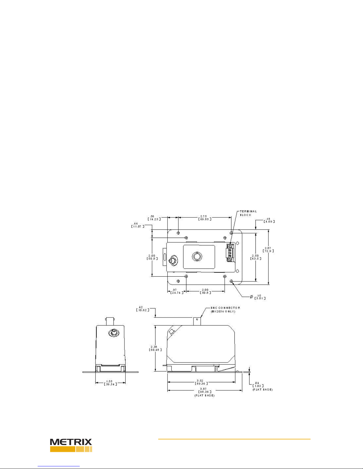
The driver or transmier comes as a DIN rail mount. The below gure shows the unit with
the oponal at base mounng plate, Metrix part number 9647. The 9647 mounng plate
has two dierent hole paerns. One is for Metrix 5465/5488 transmiers and the other pat-
tern is for Metrix 5533, MX3300 and most other manufacturers’ probe drivers.
Figure 8: Key dimensions for at base installaon.
Doc# 100545 • REV C (May 2016) Page 8 of 16
MX2033 Field Wiring Installaon
The driver circuit is insulated from ground by its plasc housing. If grounding of the driver
is required, a jumper wire can be used to connect the COM terminal to one of the mount-
ing screws. Proper aenon must be given to other connecons in the circuit to prevent
unwanted ground loops which can cause improper operaon.
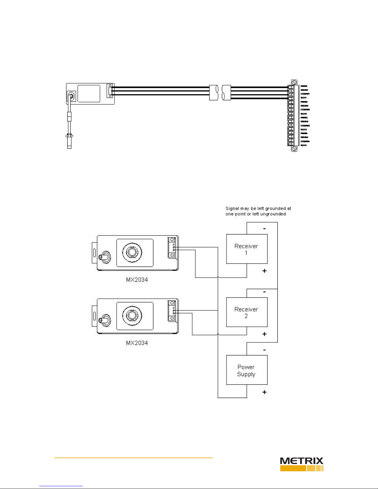
MX2034 Field Wiring Installaon
You can wire the MX2034 transmier with one or mulple receivers as shown in Figure 9 or
Figure 10.
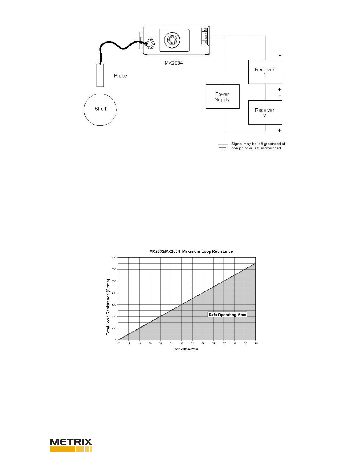
Figure 9: MX2034 wiring with individual receivers
Doc# 100545 • REV C (May 2016) Page 9 of 16
Figure 10: MX2034 wiring with mulple receivers
Connect the eld wiring (16 to 22AWG) in accordance with the appropriate diagrams. For
the MX2034, the minimum power supply voltage is 17 V plus 1 volt for each 50 Ω of loop
resistance. See Graph 1.

Doc# 100545 • REV C (May 2016) Page 10 of 16
HAZARDOUS AREA INSTALLATIONS
MX2034 (DPS) General Requirements
Connect the eld wiring in accordance with Metrix drawing 100508 for ATEX installaons and
100506 for North American installaons.
Baseefa 05ATEX0195X Exia; Intrinsically Safe
II 1G Ex ia IIC T4 Class I, Div. 1, Groups A, B, C,D
(-40°C < Tamb < 85°C) Temp Code T4 (–40°C ≤ Ta ≤ +85°C)
SPECIAL CONDITIONS OF SAFE USE
Mount the DPS in a separate enclosure capable of withstanding a 7 joule impact and provid-
ing a minimum ingress protecon of IP54.
Consider that the DPS is not capable of withstanding the insulator test required by Clause
6.4.12 of EN50020:2002 when installing the DPS.
The DPS cannot be repaired in the eld. Replace a failed DPS with an equivalent unit.
Do not expose the DPS to dust condions.
Do not install the DPS where it may be subjected to mechanical and excessive thermal
stresses or where it may be aacked by exisng or foreseeable aggressive substances.
Install the DPS such that its terminals are protected to at least IP20.
Protect the plasc DPS enclosure from impact and fricon.
Perform a risk assessment in accordance with Clause 10 of EN60079-25 and install lightning
protecon arresters as deemed necessary.
WARNING – SUBSTITUTION OF COMPONENTS MAY IMPAIR INTRINSIC SAFETY. AVERTISSEMENT:
LA SUBSTITUTION DE COMPOSANTS PEUT COMPROMETTRE LA SECURITE INTRINSEQUE.
WARNING – TO PREVENT IGNITION OF FLAMMABLE OR COMBUSTIBLE ATMOSPHERES, DIS-
CONNECT POWER BEFORE SERVICING.
WARNING – TO PREVENT IGNITION OF FLAMMABLE OR COMBUSTIBLEATMOSPHERES, READ,
UNDERSTAND, AND ADHERE TO THE MANUFACTURER’S LIVE MAINTENANCE PROCEDURES.
Doc# 100545 • REV C (May 2016) Page 11 of 16
Intrinsically Safe Installaon in Hazardous Environments
The driver requires a minimum of 17 VDC for proper operaon. The voltage drop across the
specied zener barriers on the installaon drawings with a 20 mA loop current is 8.1 VDC. The
minimum loop power supply voltage required is 25.1 VDC plus 1 volt for each 50 Ω of loop
resistance. The maximum loop power supply voltage that may be applied to the safety barrier
is 26 VDC. Therefore, the maximum loop resistance with a 26 VDC supply is 45 Ω.
Example: Single wire resistance = 5 Ω
Resistance of receiver = 50 Ω
Total loop resistance = 55 Ω
Minimum supply voltage = 55 Ω (1VDC/50 Ω) + 25.1 VDC = 26.2 VDC
Permanent wiring connecon to the Dynamic Signal terminal or BNC connectoris not allowed
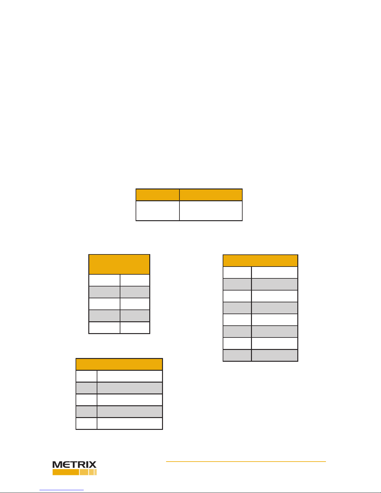
under the intrinsic safety cercaon requirements. Table 1 lists recommended zener barri-
ers. Other barrier manufacturers can be used as long as they meet the required parameters
noted on the installaon drawings.
DPS Model MTL Barrier Model
MX2034 MTL 787(+) or
equivalent
Table 1: Recommended Barriers
INPUT/OUTPUT PARAMETERS
Power Terminal
Enty Parameters
Ui28V
Ii93mA
Pi0.66W
Ci18nF
Li0
Table 2: Power Terminal Enty Parameters
UL/CSA Parameters
Voc = 5.36V
Ioc = 93mA
Ca= 62uF
La= 8.5mH
Po= 0.5W
Table 4: Probe Connector
UL/CSA Enty Parameters
ATEX Parameters
Uo5.36V
Io3.64mA
Po20mW
Ci24nF
Li110μH
Co32μF
Lo500μH
Lo/Ro> 1000μ/H/Ω
Table 3: Probe Connector
ATEX Enty Parameters

Doc# 100545 • REV C (May 2016) Page 12 of 16
Installaon in Zone 2 and Div. 2 Areas
Zone 2 Area
Baseefa 06ATEX0113X Ex nA IIC T4 (–40°C ≤ Ta ≤ +85°C)
SPECIAL CONDITIONS OF SAFE USE:
Connect the eld wiring in accordance with Metrix drawing 100515.
When the DPS is being used in accordance with the type of protecon: Ex nA IIC T4 (–40°C ≤
Ta ≤ +85°C), the apparatus must be mounted in an enclosure capable of withstanding a 7 joule
impact (at -40°C if non-metallic) and provide a degree of ingress protecon of at least IP54.
The DPS is cered as a component only and must be installed in a suitable enclosure ac-
ceptable to local authories.
Field wiring from the safe area to the transmier must conform with the local electrical
code. The transmier provides a non-incendive circuit to probe and extension cable, which
therefore require no further electrical protecon.
Do not use Dynamic Signal BNC connector or terminal unless area is known to be non-haz-
ardous.
Transmier is cered as a component only and must be installed in a suitable enclosure ac-
ceptable to local authories.
The driver is not capable of withstanding the insulator test required by Clause 6.4.12 of
EN50020:2002. This must be taken into account when installing the driver.
Div. 2 Area
Class I Division 2 Hazardous Locaons (Non-Incendive), when installed per drawing 100512.
THIS EQUIPMENT IS SUITABLE FOR USE IN CLASS I, DIVISION 2, GROUPS A, B, C, D OR NON-
HAZARDOUS LOCATIONS ONLY.
WARNING - EXPLOSION HAZARD – SUBSTITUTION OF COMPONENTS MAY IMPAIR SUITABILITY
FOR CLASS I, DIViSION 2.
AVERTISSEMENT - RISQUE D’EXPLOSION – LA SUBSTITUTIOND E COMPOSANTSP EUTR ENDRE
CE MATERIEL INACCEPTABLE POUR LES EMPLACEMENTS DE CLASSE I, DIVISION 2.
MX2033 Intrinsically Safe Installaon in Hazardous Environments
Baseefa 05ATEX0195X Exia; Intrinsically Safe
II 1G Ex ia IIC T4 Class I, Div. 1, Groups A, B, C,D
(-40°C < Tamb < 85°C) Temp Code T4 (–40°C ≤ Ta ≤ +85°C)
Connect the eld wiring in accordance with Metrix drawing 100509 for ATEX installaons and
100506 for UL/CSA installaons. The driver requires a minimum of 17 VDC for proper opera-
on. The voltage drop across the specied zener barriers on the installaon drawings with a
10 mA supply current is 4.1 VDC. The minimum loop power supply voltage required is 25.1
VDC plus 1 volt for each 50 Ω of loop resistance. The maximum loop power supply voltage
that may be applied to the safety barrier is 26 VDC. Therefore, the maximum loop resistance
with a 26 VDC supply is 45 Ω.

Doc# 100545 • REV C (May 2016) Page 13 of 16
Example: Single wire resistance = 5 Ω
Resistance of receiver = 50 Ω
Total loop resistance = 55 Ω
Minimum supply voltage = 55 Ω (1 VDC/50 Ω) + 25.1 VDC = 26.2 VDC
SPECIAL CONDITIONS OF SAFE USE:
The apparatus must be mounted within a separate enclosure capable of withstanding a 7
joule impact and providing a minimum ingress protecon of IP54.
The transmier is not capable of withstanding the insulator test required by Clause 6.4.12 of
EN50020:2002. This must be taken into account when installing the driver.
The driver cannot be repaired in the eld and must be replaced by an equivalent unit. The
driver is not to be exposed to dust condions.
The driver should not be installed where it may be subjected to mechanical and excessive ther-
mal stresses or where it may be aacked by exisng or foreseeable aggressive substances.
The apparatus enclosure is made from plasc which must be protected from impact and fricon.
Installer must perform a risk assessment in accordance with Clause 10 of EN60079-25 and
install lightning protecon arresters as deemed necessary.
WARNING – SUBSTITUTION OF COMPONENTS MAY IMPAIR INTRINSIC SAFETY.
AVERTISSEMENT: LA SUBSTITUTION DE COMPOSANTS PEUT COMPROMETTRE LA SECURITE
INTRINSEQCJE.
WARNING – TO PREVENT IGNITION OF FLAMMABLE OR COMBUSTIBLE
ATMOSPHERES, DISCONNECT POWER BEFORE SERVICING.
WARNING – TO PREVENT IGNITION OF FLAMMABLE OR COMBUSTIBLE ATMOSPHERES, READ,
UNDERSTAND, AND ADHERE TO THE MANUFACTURER’S LIVE MAINTENANCE PROCEDURES.
INPUT/OUTPUT PARAMETERS
Power Terminal
Enty Parameters
Ui30V
Ii101mA
Pi0.915W
Ci17.6nF
Li110μH
Table 5: Power Terminal
Enty Parameters.
ATEX Parameters
Uo5.36V
Io3.64mA
Po20mW
Ci24nF
Li110μH
Co32μF
Lo500μH
Lo/Ro> 1000μ/H/Ω
Table 6: Probe Connector
ATEX Enty Parameters.
UL/CSA Parameters
Voc = 5.36V
Ioc = 93mA
Ca= 62μF
La= 8.5mH
Po= 0.5W
Table 7: Probe Connector
Intertek Enty Parameters.

Doc# 100545 • REV C (May 2016) Page 14 of 16
Table 8 lists recommended zener barriers. Other barrier manufacturers can be used as long
as they meet the required parameters noted on the installaon drawings.
Installaon in Zone 2 and Div. 2 Areas
Zone 2 Area
Baseefa 06ATEX0113X Ex nA IIC T4 (–40°C ≤ Ta ≤ +85°C)
SPECIAL CONDITIONS OF SAFE USE:
Connect the eld wiring in accordance with Metrix drawing 1113106.
When the apparatus is being used in accordance with the type of protecon: Ex nA IIC T4
(–40°C ≤ Ta ≤ +85°C), the apparatus must be mounted in an enclosure capable of withstand-
ing a 7 joule impact (at -40°C if non-metallic) and provide a degree of ingress protecon of at
least IP54.
Driver is cered as a component only and must be installed in a suitable enclosure accept-
able to local authories.
Field wiring from the safe area to the transmier must conform with the local electrical code.
The transmier provides a non-incendive circuit to probe and extension cable, which there-
fore require no further electrical protecon.
The driver is not capable of withstanding the insulator test required by Clause 6.4.12 of
EN50020:2002. This must be taken into account when installing the driver.
Div. 2 Area
Class I Division 2 Hazardous Locaons (Non-Incendive), when installed per drawing 100512,
sheet 2.
THIS EQUIPMENT IS SUITABLE FOR USE IN CLASS I, DIVISION 2, GROUPS A,B, C, D OR NON-
HAZARDOUS LOCATIONS ONLY.
WARNING - EXPLOSION HAZARD – SUBSTITUTION OF COMPONENTS MAY IMPAIR SUITABILITY
FOR CLASS I, DIViSION 2.
AVERTISSEMENT - RISQUE D’EXPLOSION – LA SUBSTITUTIOND ECOMPOSANTSP EUTR ENDRE
CE MATERIEL INACCEPTABLE POUR LES EMPLACEMENTS DE CLASSE I, DIVISION 2.
DPS Model MTL Barrier Model
MX2033 MTL 796(-) or
equivalent
Table 8: Recommended Barriers.

Doc# 100545 • REV C (May 2016) Page 15 of 16
CAUTION: Do not connect test equipment
or cables to the driver unless the area has
been determined to be non-hazardous.
This electronic equipment was manufactured according to high quality stan-
dards to ensure safe and reliable operaon when used as intended. Due to
its nature, this equipment may contain small quanes of substances known
to be hazardous to the environment or to human health if released into the
environment. For this reason, Waste Electrical and Electronic Equipment
(commonly known as WEEE) should never be disposed of in the public waste
stream. The “Crossed-Out Waste Bin” label axed to this product is a reminder
to dispose of this product in accordance with local WEEE regulaons. If you
have quesons about the disposal process, please contact Metrix Customer
Services.
ENVIRONMENTAL INFORMATION
CALIBRATION AND SIGNAL ANALYSIS
General
Factory calibrated units are for use with the specied probe, extension cable and target part
numbers. Use the User conguraon soware (see secon 0) to congure un-congured
units before pung into service. For maximum accuracy, calibrate the driver with the probe
and cable to be used.

Doc# 100545 • REV C (May 2016) Page 16 of 16
All trademarks, service marks, and/or registered trademarks used in this
document belong to Metrix Instrument Company, L.P. except as noted below:
Teon® is a mark of DuPont in the United States and other countries.
© 2014, Metrix Instrument Company, L.P. All rights reserved.
info@metrixvibraon.com
www.metrixvibraon.com
8824 Fallbrook Dr. Houston, TX 77064, USA
Tel: 1.281.940.1802 • Fax: 1.713.559.9421
Aer Hours (CST) Technical Assistance: 1.713.452.9703
Other manuals for MX2033
2
This manual suits for next models
1
Table of contents
Other Metrix Transmitter manuals


