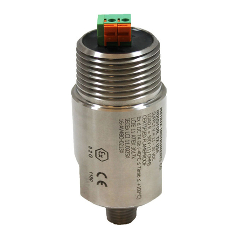
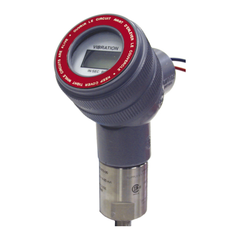
Metrix ST5491E User manual

ST5491E 2-WIRE SEISMIC VIBRATION TRANSMITTER
Installaon Manual
DOC# M9344 • REV K (April 2022)
OVERVIEW
The Model ST5491E Seismic Vibraon Trans-
mier is the latest version of an established
series of transmiers from Metrix. The
ST5491E is the indicang version of Metrix
Model ST5484E and comes with an integral
2-1/2 digit LCD indicator for local vibraon
readout. It incorporates state-of-the-art
electronic components and circuits. It also
oers several new opons in terms of fea-
tures and conguraons.
The transmier combines a vibraon sensor
and signal condioner in a single package.
They provide the ideal soluon for sensing
machinery vibraon level and transming
a proporonal 4-20 mA signal directly to a
PLC, DCS, monitor, or computer. Typical ap-
plicaons include low- and medium-speed
machines such as fans, blowers, pumps, mo-
tors, and centrifuges. The transmier can
be supplied with oponal screw cover elbow
ngs for connecng exible conduit.
The transmier is all solid state, has no
moving parts, and is encapsulated in a
stainless steel housing. The LCD indicator
is packaged in a sealed module that can be
posioned in 90° increments with the elbow
ng to allow proper viewing when the
transmier is installed. Each transmier is
factory calibrated to the sensivity marked
on the label.

Doc# M9344 • REV K (April 2022) Page 2 of 8
INSTALLATION
1. MOUNTING
The transmier body must be solidly mounted to the machine surface. See the secon
Typical Transducer Placement. Dierent machine preparaons are required for the two
basic transmier mounng styles; NPT (Naonal Pipe Thread) and machine thread (UNF and
Metric). Transmiers with the NPT type mounng stud are secured by the thread engage-
ment and the base of the transmier does not come in contact with the machine surface.
On the other hand, transmiers with the machine thread studs must make contact with the
machine surface. The transmier base must make square and direct contact. This requires
preparing the surface of the machine with a 1 1/2 inch counter bore (surfacing tool). This
tool can be used with a portable drill equipped with a magnec base take care such that the
tapped and threaded hole is perpendicular to the machined surface. The transmier must
make contact all the way around its base surface. Contact Metrix for more detailed instruc-
ons for using a counter bore.
If installing a transmier with a standard 1/4 inch NPT stud, drill a hole using a 7/16 inch bit,
5/8 inch deep. Then tap using a 1/4 - 18 NPT (tapered pipe tap). Hand ghten the transmit-
ter and then turn an addional 1 to 2 turns using a wrench on the wrench ats. Do not use
a pipe wrench. A pipe wrench can apply extreme forces to the body and potenally damage
electronic components. A minimum of ve threads of engagement should be made. A 1/4
inch to 1/2 inch NPT bushing is available for mounng the transmier in exisng 1/2 inch NPT
holes. Also, a Metrix Model 7084 Flange Adapter can be used between the transmier and
the machine surface when there is not enough surface thickness to drill and tap a hole. The
ange adaptor mounts with three small screws. See Accessories.
If installing a transmier with one of the straight machined thread sizes, follow standard
drill and tap procedures. Be sure to not drill a hole larger that the counter bore pilot diam-
eter before using the counter bore to prepare the machine surface. Drill out the hole with
the correct tap drill size aer preparing the surface.
The sensive axis of the transmier is in line with the mounng stud. The transmier can
be oriented in any (0 to 360 degree) posion.
2. WIRING
The ST5491E is connected like any other loop powered transmier. The following is a sum-
mary based on area designaons.
2.A SAFE AREA INSTALLATION
Connect the eld wiring in accordance with the appropriate diagram on page 3. The ST5491E
transmier requires a minimum of 13 VDC for proper operaon. The minimum loop power
supply voltage required is 13 VDC plus 1 volt for each 50 ohms of loop resistance.
ST5491E Example: Signal wire resistance = 10 W
Resistance of receiver = 250 W
Total loop resistance = 260 W
Minimum supply voltage = 260 W (1 VDC/50 W) + 13 VDC = 18.2 VDC

Doc# M9344 • REV K (April 2022) Page 3 of 8
The maximum loop power supply voltage that may be applied is 30 VDC. The maximum loop
resistance (RL) is calculated by the equaon:
RL = 50 (VS - 13) W
Example: RL = 50 (24 - 13) = 550 W for 24 VDC loop supply.
2.B EXPLOSION-PROOF INSTALLATION IN HAZARDOUS LOCATIONS
ST5491E transmiers are CSA cered explosion-proof, Class I (C & D); Class II (E, F & G,).
Connect the eld wiring in accordance with the appropriate diagram on page 3. Refer to
paragraph 2.A for loop voltage and resistance requirements. All conduit and juncon boxes
used must be cered explosion-proof for the class, division and group required by the
applicaon. Installaon of the transmier must meet all of the explosion-proof installaon
requirements of the local governing agency and facility safety procedures.
3. ELECTROMAGNETIC COMPATIBILITY
To meet the requirements of electromagnec compability in areas of high electromagnec
interference, the eld wiring must be:
1. Shielded twisted pair cable enclosed in grounded metallic conduit, or
2. Double shielded twisted pair cable with a metallic body cable gland ng and with the
outer shield grounded.
WIRING DIAGRAMS
Use standard two-conductor, twisted pair, shielded wiring for the long run to the instrumenta-
on enclosure. The transmier is connected like any other loop powered end device.
3.A CONNECTION TO PLC OR OTHER INDICATING INSTRUMENT
The rst step in conguring the PLC, DCS, or other recording instrument is to determine the
source of power. The ST5491E requires loop power be supplied to it. Some Analog Input
channels, on a PLC or DCS, for example, provide this power from within. If they do not
provide power, an external power supply must be provided. Connect the transmier eld
wiring using standard instrumentaon pracces.

Doc# M9344 • REV K (April 2022) Page 4 of 8
Scaling of the display is on the basis of the range of the transmier. The measurement pa-
rameter name is “vibraon” and the units are “ips” (inches per second) or “mm/s” (millime-
ters per second). The example below is based on a standard 1.0 ips transmier.
To prevent nuisance alarms, due to transient operang condions, program an alarm me
delay. Momentary “jolts” that can occur at start-up or during some operang condion
changes, do not reect a machines steady state operang condion. The indicated vibraon
level must cross the threshold level and stay above it for a preset me before any alarm ac-
on is taken. A 2- to 3-second delay is normally applied to most machinery. Consult Metrix if
you have a queson about your machines operang characteriscs.
Some rough starng machinery may also need a start-up me lockout for alarms. A start-up
lockout is dierent than a me delay. Both may be needed.
TYPICAL TRANSMITTER PLACEMENT
The ST5491E measures seismic vibraon at the aachment point on the machine. Its
sensive direcon is through its cylindrical body. It will not measure side to side moon. It
measures velocity vibraon in ips (inches per second). Velocity vibraon is a common mea-
surement for a large variety of machinery.
Figure 1 shows a typical transmier mounng for casing vibraon measurements is in the
horizontal direcon at the bearing housings. Usually the horizontal direcon is more sensi-
ve because of the way machinery is typically mounted. Figure 2 shows the ying leads be-
ing spliced in the conduit elbow. Please be aware the splice can not be made at this point if
in a hazardous area. In this case, make the splice in a second conduit hub (meeng splicing
requirements) at the end of the exible conduit.
The standard lead length is 24 inches. We recommend using the “Y” conduit elbow because it
prevents the conduit from extending too far away from the transmier, liming the likelihood
of geng snagged while working near the machinery. If a 1 inch to 3/4 inch reducer is used at
the elbow, a smaller diameter exible conduit can be used. It is always a good idea to limit
the mass that “hangs” on the transmier. The exible conduit should make a bend in order to
be sure any rigid conduit moon can not feed into the transmier body.
Vibraon Level Transmier Output PLC (or other) Scale
None 4mA +/-0.1mA 0.00 in/s
1.0 in/s 20mA +/-0.4mA 1.00 in/s

Doc# M9344 • REV K (April 2022) Page 5 of 8
TYPICAL APPLICATION AND MOUNTING ARRANGEMENT
Figure 1: Horizontal mounng for casing vibraon measurements.
i
I
1
i
Figure 2: Flying leads spliced in conduit elbow.
Figure 2a: Mounng Types
II II
11
4
II
II II
_
Machine thread style requires prepared surface (spot fac-
ing) for bottom contact
NPT thread style, no prepared surface, (spot fac-
ing), contacts through threads

Doc# M9344 • REV K (April 2022) Page 6 of 8
Set the current loop to the zero current reading of the transmier and adjust the ZERO (R7)
control for a reading of 0.00. Next set the current loop to the full scale current value and
adjust the SPAN (R6) control for the proper indicaon. Alternately adjust the ZERO and SPAN
controls as adjustments interact.
Label Full Scale Reading
1.0 in/s 1.00
19.9 mm/s 19.9
100 mm/s 100
NOTE: If a voltage source is used to generate a
current, a load resistance must be connected
in series with the ST5491E indicator module.
Failure to do so may damage the unit.
Aer calibraon, reassemble the module, reconnect the wiring, and reassemble the unit.
CALIBRATION
The ST5491E transmier has been factory calibrated for the full scale vibraon level marked on
the label. If the calibraon is in doubt the unit can be veried in the eld by following the pro-
cedures outlined below. Note that there are no Zero and Span adjustments on the transmier.
1. Zero Vericaon In the absence of vibraon the output current should be 4 mA ±0.1 mA.
If the ambient vibraon is more than 2% of full scale, the transmier should be removed from
the machine and placed on a vibraon free surface for this measurement. Oen a piece of
foam can be used to isolate the transmier from external moon.
2. Span Vericaon Subject the transmier to a known vibraon within the full scale range
marked on the label. If using a portable vibraon shaker where it can be tested at full scale,
the output should be 20 mA ±0.4 mA. If using another reference, like a similar machine, calcu-
late the current value on a proporonal basis.
The output level can also be compared to a vibraon level read on a portable vibraon meter.
This reading should be taken as close to the transmier locaon as possible.
If you shake the transmier by hand you can produce a high output as long as there are no
high pass lters. Check the conguraon for lters. There is no way of knowing the expected
output when shaking it by hand.
3. Digital Indicator Calibraon of the Digital Indicator requires paral disassembly of the
ST5491E. Remove the Digital Indicator threaded cover. Carefully remove the electronics mod-
ule using a small at head screwdriver. Note how the transmier wires are connected before
disconnecng them. Remove the retaining wire from the boom of the module and carefully
remove the electronics board assembly from the module housing. Connect the electronics
module is series with a current loop that can be accurately set from 4.0 mA to 20.0 mA +/- 0.1
mA.

Doc# M9344 • REV K (April 2022) Page 7 of 8
8201-001, Conduit Union
Fits between transmier and 8200-001 conduit elbow to facilitate installaon and
wiring where there is not enough room to rotate the elbow. Suitable for Class I, Div.
1 (Grps A, B, C & D) and Class II, Div. 1 (Grps E, F & G), hazardous areas. Material: zinc
plated steel.
7084-001, Stainless Steel Flange Mount Adaptor
Provides a means to surface mount transmiers rather than NPT stud (½”: NPT center
hole). Three equally spaced 6.6 mm (0.26’) diameter mounng holes on 38 mm
(1.50”) diameter circle.
7084-002, Flange Mount Adaptor
Same as 7084-001, except center hole is ¼” NPT. Material: stainless steel
8253-002, Bushing
Bushing for ½” NPT mount when screwed onto standard ¼” NPT base. Material: stain-
less steel.
8169-75-002-XXX, Two-wire, Cable Assembly
2 conductor (20 AWG) twisted, shielded PVC jacketed cable, with plated steel grip for
cable strain relief, male ¾” NPT end. Specify -XXX for length in feet. Example: 8169-
75-002-010 =10 (3.1M). Material: zinc plated steel.
93818-004, Cable Grip Strain Relief Fing
3/4” NPT male thread to cable grip. Diameter range: .156” to .25”. Complete with
sealing ring, locknut and hot dip / mechanically galvanized nish. Suitable for NEMA 4
enclosures.
93818-018, Armored Cable Grip Strain Relief Fing
3/4” NPT male thread to cable grip. Armor diameter range: .40” to .50”. Complete
with sealing ring, locknut and a hot dip / mechanically galvanized nish. Suitable for
NEMA 4 enclosures.
CONNECTION
OPTIONAL ACCESSORIES
The ST5491E is available with dierent mounng opons. The performance of the transmit-
ter does not change (except for the dynamic output opon, discussed).
MOUNTING

Doc# M9344 • REV K (April 2022) Page 8 of 8
HAZARDOUS AREA APPROVALS
MODEL ST5491E
UL Approval
(North
America):
CSA Markings:
Models ST5491E-XXX-XX1X-XX:
Class I, Div 2, Groups C,D;
-10°C≤Tamb≤+70°C
Model ST5491E-XXX-XX2X-XX:
Class I, Div 1, Groups C,D; Class II, Div
1, Groups E,F,G; -10°C≤Tamb≤+70°C;
Vmax=29.6V, Imax=100mA, Vi=70.4nF,
Li=0.5uH
CSA/UL Standards:
CSA C22.2 0-10
CSA C22.2 25-1966
CSA C22.2 30-1986
CSA C22.2 94-M91
CSA C22.2 157-M1992
CSA C22.2 61010-1-12
UL 61010-1
UL 50
UL 913
UL 1203
ANSI/ISA-12.12.01-2011
WARNING: DO NOT OPEN
WHEN ENERGIZED
ATTENTION: NE PAS OU-
VRIR QUAND ÉNERGISÉ
EP : Certied explosion proof,
Class I, Groups B,C,D ; Class II,
Groups E,F,G
« SEAL NOT REQUIRED »
This electronic equipment was manufactured according to high quality standards to ensure
safe and reliable operaon when used as intended. Due to its nature, this equipment may
contain small quanes of substances known to be hazardous to the environment or to human
health if released into the environment. For this reason, Waste Electrical and Electronic Equip-
ment (commonly known as WEEE) should never be disposed of in the public waste stream. The
“Crossed-Out Waste Bin” label axed to this product is a reminder to dispose of this product
in accordance with local WEEE regulaons. If you have quesons about the disposal process,
please contact Metrix Customer Services.
ENVIRONMENTAL INFORMATION
info@metrixvibraon.com
www.metrixvibraon.com
8824 Fallbrook Dr. Houston, TX 77064, USA
Tel: 1.281.940.1802 • Fax: 1.713.559.9421
Aer Hours (CST) Technical Assistance: 1.713.452.9703
Table of contents
Other Metrix Transmitter manuals
