manuals.online logo
Brands
  1. Home
  2. •
  3. Brands
  4. •
  5. Metro DataVac
  6. •
  7. Construction Equipment
  8. •
  9. Metro DataVac Roman-Tile Installation guide

Metro DataVac Roman-Tile Installation guide

Indicates critical areas of installation
Metro Roman Tile Installation 1
These install details are provided to demonstrate the recommended
installation method for Metro Roof products and accessories.
The details and information in this document reflect current roofing prac-
tices used in the United States. Consult with Metro Roof Products for
additional information.
INSTALLATION DETAILS
Issued January 23rd, 2005
Front
©Copyright, all rights reserved
Indicates critical areas of installation
Metro Roman Tile Installation 2
General
Metro Roman Tile panels are Installed on new or existing roofs
pitched a minimum of 2-½:12 (12 degrees). An underlayment is to
be installed as per local code and manufacturers instructions.
1”x4” or 2”x2” panel battens may be used over a solid sheathed
roof deck. For installation using 1”x4” counter battens, 2”x2” panel
battens must be used (see Counter Battens). Panel battens are
installed parallel to the ridge/fascia. The first panel batten is posi-
tioned flush with the fascia or batten build-up. The second panel
batten is positioned 13-¾” from the fascia to accommodate the
“Bird-Stop” metal.
2”x2” ridge battens or double stacked 1”x4” pcs. are used to pro-
vide approximately 1½”of build-up height for hip and ridge pcs. Hip
battens are installed directly on top of each intersecting panel bat-
ten, so that cut panels can be fitted
against the battens.
Battens are fastened to supporting framing members as per code
and Metro instructions.
Wood panel battens can be 2”x2”, 1”x3” or 1”x4”. Consult Metro
regarding approved steel purlin sections. Precise panel batten
spacing is critical because the rear of each Metro panel must fit
snuggly against the batten.
Panel Battens
Ridge Battens
14 ½” o/c panel batten spacing
is critical to allow panels to fit
properly.
13 ¾”
For the 1st course of panels, a spacing of
13 3/4” is used when Metro Roman Bird-
stop is installed at the fascia.
Space Ridge/Hip
battens 5” apart.
©Copyright, all rights reserved
Indicates critical areas of installation
Metro Roman Tile Installation 3
2”x2” Batten
1”x4” Counter Batten
Underlayment
1”x4” counter battens are placed approximately 24” o/c
directly over rafters. Fasteners must penetrate 1” into or
through the roof framing members and be placed 12” o/c.
Counter Battens
When reroofing over wood shingles or shakes, the existing
roof is cut back around the perimeter to allow a build-up
of 1”x4”, 2”x2” or a combination of both, to provide a solid
nailing foundation. Wood is built up to match the underside
of the 1”x4” counter battens placed on top of the existing
roof. Consult local codes for other specific requirements.
Drip Edge
Counter battens (1”x4”) are used when roofing over uneven
surfaces or for additional ventilation, i.e. to create a cold roof
application.
A standard “Drip-Edge” flashing is used along the eave/fas-
cia, and should be installed over the batten, as shown.
Fascia build-up for roofing
over existing roofs.
12”
24”
When counter battens are used, install 1”x4” battens
down both sides of valley flashing as shown.
©Copyright, all rights reserved
Indicates critical areas of installation
Metro Roman Tile Installation 4
Metro Tile Rake metal is installed along the rake edges as
shown. Tile Rake metal aids in positioning Metro Trim Caps,
and is placed on the wood build-up. The Metro Trim Caps
cover battens and folded up Metro panels, as shown.
Rake Metal
1”
Install 20” (508mm) Double ‘V’ Valley metal overlapping a
min. of 4” (100mm). Valleys are attached with site fabricated
clips as shown. Washer and rubber grommet screws are
acceptable at the outside locations, as shown above.
Full panels are laid from the top of the roof (1st full course
from the ridge) down to the fascia. Roman Tile panels are
laid from right to left.
Each Roman Tile panel is fastened to the battens with a
minimum or four (4) .131” dia x 2-3/8” long corrosion resistant
ring shank nails through the front down turn of the panels
as shown. #10 x 2” long 1/4” hex head corrosion resistant
screws may be used in place of nails.
Panel Layout & Fastening
Stagger Metro Roman Tile panels 1-2 “’pan” modules to
eliminate negative visual effects of continuous side-laps.
Fastening
Location
Overlap each panel
over the 2” side-lap
1
2
3
4
20” Double ‘V’ Valley
Extend valley a min of 1” past the
fascia/eave edge.
Metro panels are fastened on the right
side of each overlapped pan as shown.
©Copyright, all rights reserved
Indicates critical areas of installation
Metro Roman Tile Installation 5
Fastening First Course
Valley Panels
Cut line
Bend line
Bend panel down to fit
into valley metal
Start the 1st panel 12” (300mm) from the
valley edge. This allows for a valley cut
section to be securely fastened to the roof
deck without penetrating the valley flashing.
Measure, mark and cut panels to fit
tightly against valley center (reverse
‘V’). Fasten valley section panels to
roof decking similar to the other panels
without penetrating valley flashing.
Mark the bend line
1½” in from the cut
line.
1”
Fasten the first course of panels at the raised panel sec-
tion, through the fascia metal, and into the 1”x4” batten.
This is the only place where it is acceptable to fasten
panels through the top.
©Copyright, all rights reserved
Indicates critical areas of installation
Metro Roman Tile Installation 6
Hip Panels
Bend line Cut line
2”
Hip cuts are measured, cut and bent similarly to valleys. Each hip
panel is bent up a min. of 1½” and fastened against the hip board.
Bird-Stop Metal
The Bird-Stop riser metal creates a ¾”
off-set from the fascia. The use of this
‘Bird-Stop’ requires standard Drip-Edge
metal to be installed on a (1”X4” or
2”X2”) support batten.
Bend Line
Cut line
½” is deducted from the actual measurment when
making hip cuts.
Bird stop metal extends into valleys as
shown.
The second panel batten is
positioned 13-¾” from the fascia
to accommodate the Bird-Stop
metal.
©Copyright, all rights reserved
Indicates critical areas of installation
Metro Roman Tile Installation 7
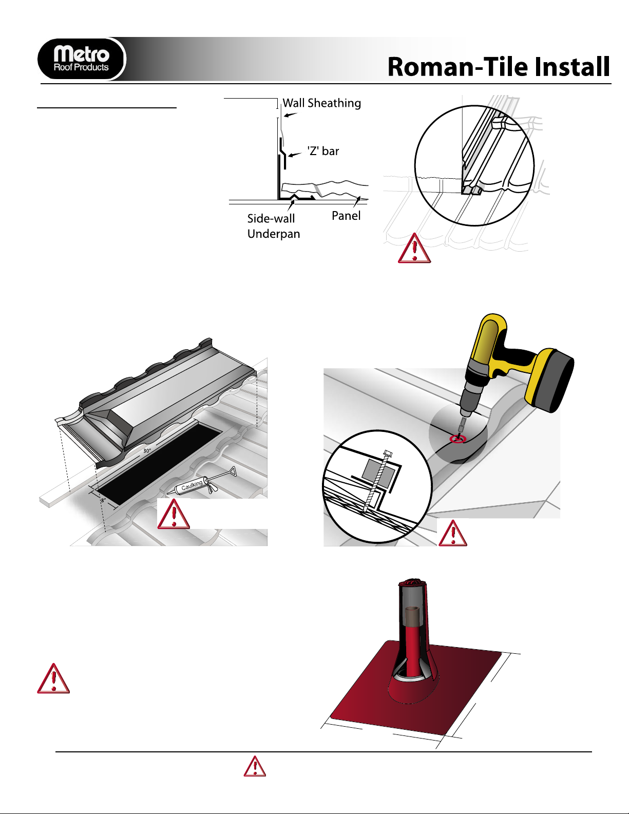
SIDE-HEAD WALL/CHIMNEY/SKYLIGHT
The following details apply to any square cornered protrusion through a roof.
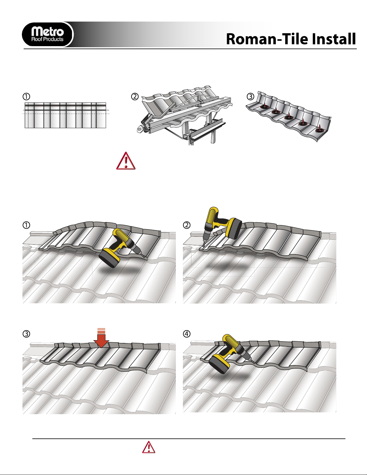
At front of chimney, measure, cut, and fold
up panel 2”. Cut panels on a 45 degree
angle as shown and fold tabs around
chimney.
On sides of chimney, cut and fold up
panels 2” as shown.
At back of chimney, seal each top corner
section. Keep panel battens away from
saddle as shown.
At back of chimney, install chimney saddle
as shown. Extend saddle a minimum of 6”
past each side of chimney. Hem ends 1” to
keep water on saddle flashing.
Install a section of Metro Roman Foam
Closure across the chimney saddle as
shown (align with Roman profile).
Cut and
flatten
2”
45
CUT
45
NO BATTEN
Roman Foam
Closure
6”
1” Hem
4.
1. 2. 3.
6”
2”
Fold flap down to
fit tight against
saddle bend
2”
Panel
Batten
Saddle
5. 6.
Always start from the bottom of the item
being flashed to ensure correct weather
protection.
Counter Flashing metal or Z-bar covers
bent up edges of panels.
Apply a bead of sealant across Foam
Closure and ‘Seat’ back cut-section panel
onto Foam Closure. Panels are fastened
through the front downturn of the panels,
the Foam Closure and saddle into deck-
ing.
Where applicable, cut and fold panels to
overlap the hand fabricated hem on the
sides of the chimney saddle.
©Copyright, all rights reserved
Indicates critical areas of installation
Metro Roman Tile Installation 8
ALTERNATE FLASHING DETAIL
Side-wall Underpan metal is covered
with counter flashing or standard Z-bar.
Panel front down-turn is flared out
to allow Underpan to exit onto panel
below.
Fold up nose of panel where
underpan metal exits on top of
panels below.
SMARTvent - Roman Tile
8”
30”
Metro Roman Tile SMARTvents are used in place of regular panels where ventilation is required. The vents are installed similar to
panels after cutting ventilation hole in decking (approximately 8” x 30”). A Metro Roman Tile SMARTvent provides approximately
82sq. inches of Net Free Vent Area (NFVA). Care should be taken to adequately ventilate the buliding.
Building codes require a minimum NFVA of 1/300 the area of the space to be ventilated (attic).
Secure SMARTvent with
screws (#10x2” HH)(50mm)
Seal back up-turn prior to
overlaying panel.
The Metro ‘Sandwhich’ method should be used if a
vent location prevents a SMARTjack 3-in-1 from be-
ing folded up and over a panels back flange,
18”
18”
SMARTjack and SMARTsleeve
Metro offers both a SMARTjack and SMARTsleeve for use
with it’s stone-coated roof panels. The Metro 3-in-1 SMART-
jack is a moldable stone-coated roof flashing and is avail-
able in a small(SMARTjack12”x16”) and large (Roman
SMARTjack18”x18”) base size. Apply sealant under 3-in-1
SMARTjacks.
©Copyright, all rights reserved
Indicates critical areas of installation
Metro Roman Tile Installation 9
Cut
Cut panel battens a min. of 6” from the protruding pipe.
Flatten the panel directly below the pipe to avoid a
hump. Cut and hem a lip around the perimeter of the
SMARTjack on the section placed above the panel bat-
ten. Install a block behind the protrusion to support the
back of the SMARTjack.
Slide the SMARTjack into place. Mold base of
SMARTjack to conform with panel.
Measure, mark, and cut Roman panels to cover back section
of SMARTjacks. Seal around flashing.
For added protection and appearance, SMARTsleeves
are cut to conform to the panels and are installed over
pipes. Sleeves are fastened with a screw through the
front of the SMARTsleeve into the SMARTjack.
SMARTjack and SMARTsleeve
©Copyright, all rights reserved
Indicates critical areas of installation
Metro Roman Tile Installation 10
Ridge Panels
The top course of panels require cut and bent panels to complete the ridge line.
Always bend the ridge panels before cut-
ting as they deform slightly and are difficult
to install. Deduct ½” from measurements
and mark both bend and cut lines for each
panel.
Bend all ridge panels using Metro’s top bender.
The following steps should be followed to ensure adequate weather protection along the ridge.
Bend Line
Cut Line
Fasten panels first at bottom right corner. Then fasten panels at bottom far left corner. Panels are then
pushed down and fastened into place.
Push back of panel into position against ridge batten before
fastening.
Additional fasteners are applied as necessary.
After bending and cutting, reshape
panels to match existing panel
courses.
©Copyright, all rights reserved
Indicates critical areas of installation
Metro Roman Tile Installation 11
Cut out
6”
Roman Foam
Closure Strip
Short Course
This detail is needed where the fascia/eave steps out from the main roof course line.
Where panels intersect with a stepped fascia, stop panel bat-
tens approximately 6” away from new fascia line. If nessesary,
notch, cut, and flatten panel at this intersection as shown.
The 1st full panel (short course) piece is notched and fitted as
shown.
Place Metro Roman Foam Closure strip in line with main
coursing row. Use sealant to secure.
Install full panels aligned with main courses. Fasten with
screws, through front down-turn of panel through the Foam
Closure strip, and into the panel below as shown.
Top Course Metal
Roman Top Course metal may be used to avoid bending and
cutting full panels at the ridge or chimney.
Roman Top Course metal can also be used at the front of chim-
neys and skylights.
Top Course Metal is used where the last panel
course before the ridge measures 4½” or less.
5-1/2”
1-1/2”
Sealant
1-1/2”
Apply a bead of sealant between two overlapping top course
pieces.
©Copyright, all rights reserved
Indicates critical areas of installation
Metro Roman Tile Installation 12
TRIM CAP DETAILS
RIDGE CENTER CAP
At the center of a ridge line, a
small/short ridge cap, as shown,
can be made where cap pieces
meet from different directions.
RIDGE/GABLE END
Where the ridge intersects with a
gable end (rake), cut and fold the
end disc as shown to follow the Rake
Channel sections previously installed.
HIP CORNER
Notch & fold the end disc as shown to
form a closed 3-dimensional end cap.
Fit end disc to bottom hip corner with
stitch screws and install balance of trim
caps up the hip. Nail each cap on either
side of hip boards.
HIP/RIDGE INTERSECTION
Install hip caps from the bottom using
2 fasteners per trim cap. Overlap trim-
caps at hip/ridge intersection. Cut and
fit the ridge cap over both intersecting
hip caps as shown.
Attach end
disc with
stitch screws.
After installing trim caps at intersections, seal cut
edges and apply Metro basecoat and stone chip for a
complete stone coat finish.
©Copyright, all rights reserved
Indicates critical areas of installation
Metro Roman Tile Installation 13
3093 Industry Street
Oceanside CA, 92054
PH.(760) 435-9842
FX.(760) 435-1162
E-mail: [email protected]
www.smartroofs.com
Materials & Accessories:
General:
Metro RomanTile panels are produced
from Aluminum-zinc alloy coated steel
complying with ASTM A792.
Testing:
Metro RomanTile panels have been
tested according to the toughest
Building Code Standards. Testing
has been conducted to evaluate fire,
wind, penetration, water infiltration,
and durability. Information regarding
specific tests and approvals can be
obtained from Metro Roof Products.
Warranty:
Metro RomanTile panels carry a limited
warranty for fifty years. This limited
warranty is transferable and does not
cover damage due to improper handling
or installation.
Packing and Storage:
A pallet of Metro Roman Tile panels
contains 19 squares. Care should be
taken to store Metro RomanTile panels
and accessories. They should be
placed under a tarp, or placed in an area
free from moisture and debris.
Dissimilar Metals:
To avoid adverse corrosion effects
caused by dissimilar metals, COPPER
and LEAD flashings should not be
used with Metro roof products and
accessories. (refer to Metro SMARTbrief
#02004)
Roofing felt
Unless local conditions require otherwise,
a min. of either one layer of type 30, or
two layers of Type 15 lb. roofing felt (or
equivalent) should be used with Metro
RomanTile panels.
Roofing nails
Corrosion resistant .131” dia. x 2”
long ring shank roofing nails are used
to attach Metro roof products and
accessories.
Sealant/Caulking
Only exterior grade urethane or (non-
acidic) sealant should be used. Only use
Metro Repair-kit adhesive to apply stone
chips.
Finish coating
Minor scuffing of Metro RomanTile panels
can be repaired with a Touch-Up kit from
Metro Roof Products. Use the Metro
adhesive (not caulking). Unfinished
flashing materials can be painted with
durable acrylic aerosol paints. Colored
aerosol paints should never be sprayed
on stone coated panels or accessories
made by Metro Roof Products.
2.5” Head-wall Flashing
79” x 2.5”
3.3 lbs.
Stone Coated
Ventilation:
Ensure proper attic ventilation as
prescribed per local codes. Either
SMARTvents or ridge venting can be
installed to achieve adequate ventilation.
Other Items Needed:
Caulk (sealant)
Drill
Metal snips
Screw Gun
Metro Cutter (optional)
Nail gun
Roofing nails (ring shank)
Roofing felt
Hammer
Hand benders
Tape measure
Caulking gun
Side-Wall Underpan metal
120” x 4”
5 lbs.
Chimney Saddle
60” x 16”
6.75 lbs.
Metro RomanTile
52” x 16.5”
5.5 lbs.
21 pcs. per square
Barrel Cap Trim
14.5” x 6”
1 lbs.
Trim End Disc
6” x 4”
.15 lbs.
MetroTile SMARTvent
52” x 14.5” x 3.5”
10.5 lbs.
Net Free Vent Area 82.5”
20” Double ‘V’ Valley
120” x 20” x 1”
Tile Rake Metal 120”
120” x 2” x 1.75”
2.1 lbs.
‘Z’-bar Metal
79” x 2.5”
3.5 lbs.
Stone Coated
‘Bird-stop’ Metal
79” x 5”
3.75 lbs.
Stone Coated
Foam Closure
1” x 1” x 79”
Black foam
Drip Edge Flordia
120” x 2” x 2.5”
3.3 lbs.
Fascia/Counter Flashing
79” x 3.25” or 5”
3.75 lbs.
Stone Coated
Top Course
79” x 1.5” x 4.5” x 2.25”
4.10 lbs.
Stone Coated
©Copyright, all rights reserved

Popular Construction Equipment manuals by other brands

Werk-Brau PowerGrip Bucket Product and installation manual

Werk-Brau

Werk-Brau PowerGrip Bucket Product and installation manual

Wetekom 64 80 14 instruction manual

Wetekom

Wetekom 64 80 14 instruction manual

Manitowoc National Crane NBT50L Series Operator's manual

Manitowoc

Manitowoc National Crane NBT50L Series Operator's manual

Manitou MAN GO 12 Repair manual

Manitou

Manitou MAN GO 12 Repair manual

Jula 640-022 operating instructions

Jula

Jula 640-022 operating instructions

Super Handy GUO117 Operator's manual

Super Handy

Super Handy GUO117 Operator's manual

Vestil WTJ-20 Series owner's manual

Vestil

Vestil WTJ-20 Series owner's manual

Greenlee 777 instruction manual

Greenlee

Greenlee 777 instruction manual

Meec tools 005-242 operating instructions

Meec tools

Meec tools 005-242 operating instructions

Hyundai HX260FC T3 manual

Hyundai

Hyundai HX260FC T3 manual

Rubi RUBIMIX-9 SUPERTORQUE manual

Rubi

Rubi RUBIMIX-9 SUPERTORQUE manual

Sealey 500KC.V2 instructions

Sealey

Sealey 500KC.V2 instructions

Tigercat M726E Operator's manual

Tigercat

Tigercat M726E Operator's manual

Hitachi ZAXIS 250LC-7 Operator's manual

Hitachi

Hitachi ZAXIS 250LC-7 Operator's manual

Chicago Pneumatic CP9620 Instruction manual/safety instruction

Chicago Pneumatic

Chicago Pneumatic CP9620 Instruction manual/safety instruction

Di-Acro 6 instruction manual

Di-Acro

Di-Acro 6 instruction manual

TYROLIT Hydrostress FGE280B operating instructions

TYROLIT Hydrostress

TYROLIT Hydrostress FGE280B operating instructions

Toro MMX-658H-P Operator's manual

Toro

Toro MMX-658H-P Operator's manual

manuals.online logo
manuals.online logoBrands
  • About & Mission
  • Contact us
  • Privacy Policy
  • Terms and Conditions

Copyright 2025 Manuals.Online. All Rights Reserved.