KEBCO COMBIVERT F5 User manual

COMBIVERT
GB INSTRUCTION MANUAL Encoder Interface
Channel 1 Resolver
Channel 2 variable
Mat.No. Rev.
DRF5ZEM-K001 1C


Table of Contents
GB - 3
1. Safety Instructions ........................................................................................ 4
1.1 Validity ................................................................................................................4
1.2 Qualication........................................................................................................4
2. Product Description....................................................................................... 5
2.1 General...............................................................................................................5
2.2 Material number .................................................................................................5
2.3 Scope of delivery (option or replacement delivery) ............................................5
2.4 Mechanical installation .......................................................................................6
3. Description of the Interface........................................................................... 6
3.1 Channel 1 ...........................................................................................................6
3.1.1 Specications .....................................................................................................6
3.1.2 Description of the socket X3A ............................................................................6
3.1.3 Input signals channel 1.......................................................................................7
3.1.3.1 Signal tracks.......................................................................................................7
3.1.3.2 Encoder breakage recognition channel 1...........................................................7
3.1.4 Connection of the encoder .................................................................................8
3.1.5 Encoder cable ....................................................................................................8
3.1.6 Encoder line length.............................................................................................8
3.1.7 Tested encoders .................................................................................................9
3.2 Channel 2 ...........................................................................................................9
4. Start-up ......................................................................................................... 9
4.1 Special resolver................................................................................................10
5. Error Messages........................................................................................... 10

Safety Instructions
GB -4
1. Safety Instructions
Prior to performing any work on the unit the user must familiarize himself with the unit. This includes especially
the knowledge and observance of the safety and warning directions. The pictographs used in this Instruction
Manual have following meaning:
Danger Refers to danger of life by electric current.
Warning Refers to possible danger of injury or life.
Note Refers to tips and additional information.
1.1 Validity
Theinformationcontainedinthetechnicaldocumentation,aswellasanyuser-specicadviceinspokenand
written and through tests, are made to best of our knowledge and information about the application. However,
they are considered for information only without responsibility. This also applies to any violation of industrial
property rights of a third-party.
Inspection of our units in view of their suitability for the intended use must be done generally by the user.
Inspections are particulary necessary, if changes are executed, which serve for the further development or
adaption of our products to the applications (hardware, software or download lists). Inspections must be re-
peatedcompletely,evenifonlypartsofhardware,softwareordownloadlistsaremodied.
Controlling by
the user
Application and use of our units in the target products is outside of our control and
therefore lies exclusively in the area of responsibility of the user.
Use under spe-
cial conditions
The used semiconductors and components of KEB are developed and dimensi-
oned for the use in industrial products. If the KEB COMBIVERT is used in ma-
chines, which work under exceptional conditions or if essential functions, life-sup-
portingmeasuresoranextraordinarysafetystepmustbefullled,thenecessary
reliability and security must be ensured by the machine builder.
1.2 Qualication
All operations serving transport, installation and commissioning as well as maintenance are to be carried
out by skilled technical personnel (observe IEC 364 or CENELEC HD 384 or DIN VDE 0100 and national
accidentpreventionrules!).Accordingtothismanualqualiedstaffmeansthosewhoareabletorecognise
and judge the possible dangers based on their technical training and experience and those with knowledge of
therelevantstandardsandwhoarefamiliarwiththeeldofpowertransmission(VDE0100,VDE0160(EN
50178), VDE 0113 (EN 60204) as well as the approporiate regulations for your area.
Danger by high
voltage
KEB electronics components contain dangerous voltages which can cause
death or serious injury. In operation, drive converters, depending on their degree
of protection, may have live, uninsulated, and possibly also moving and hot
surfaces.
In case of inadmissible removal of the required covers, of improper use, wrong
installation or maloperation, there is the danger of serious personal injury and
damage to property.

Resolver at channel 1
GB-5
2. Product Description
Figure 1: Resolver at channel 1
2MF5280-0028 /-0029 1MF5280-0028 /-0029
X3A
Channel 1
X3B
Channel 2
X3A
Channel 1
X3B
Channel 2
X3B X3A
Channel 2 Channel 1
variable see material number Resolver
2.1 General
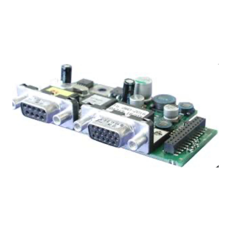
Each of the interface cards delivered by KEB include two interfaces. As there are numerous
different combinations available each interface will be described by means of separate
instructions. The instruction covers the installation of the interface card, the connection as
well as the start-up of a suitable encoder. Further information and the parameter adjust-
ments are described in the application manual for the inverter/servo.
2.2 Material number
xM F5 K8G X X X X
Term of deli-
very 0 installed Z Option, spare part
5 SSI 0025
ETTL-
Output 0029 H TTL-
Input 0028
F5 Series
applicable for housing size 1M D, E (circuit board 1MF5280-xxxx see above)
2M G…U (circuit board 2MF5280-xxxx see above)
2.3 Scope of delivery (option or replacement delivery)
•Encoder interface
•two instruction manuals
• xingbolt
•packing material

Resolver at channel 1
GB-6
2.4 Mechanical installation
All kind of works on the inverter may be carried out by authorized personnel in accordance
with the EMC and safety rules only.
•Switch inverter de-energized and await capacitor discharge time
•Pull off operator
• Remove plastic cover
• Removexingbolt
•Fix interface board beginning from the socket connector straightly
• Screwinxingbolt
•Attach plastic cover
3. Description of the Interface
3.1 Channel 1
3.1.1 Specications
Slot X3A
Interface type Resolver
Field voltage Uout 7,2 Vpp ±2%; maximum 30mA; f=9,76 kHz
Input voltage Uin 3,6 Vpp ±10 %
Gear ratio resolver 0,5
Tolerance ≤3
Bit; i.e. with 4
ms scan time and n=3000 rpm this
canleadtospeeductuationsof±20rpm
Particularities –
3.1.2 Description of the socket X3A
Figure 3.3.1 Socket X3A
5 4 3 2 1
10 9 8 7 6
15 14 13 12 11
Attention ! Plug connector only when COM-
BIVERT and supply voltage are switched off !
PIN Name Description
3 SIN_LO Sine-signal cable low
4 COS_LO Cosine-signal cable low
5 REF_N Field voltage output negative
8 SIN_HI Sine-signal cable high
9 COS_HI Cosine-signal cable high
10 REF_P Field voltage output positive
14 GND Connection for shielding of the signal cables
– Housing Shielding of the total cable

Resolver at channel 1
GB-7
3.1.3 Input signals channel 1
3.1.3.1 Signal tracks
A sine-wave voltage is output at terminals REF_HI and REF_LO at the resolver interface.
Thisvoltagesuppliestheeldwindingintheresolver.Thissignalistransmittedviaarotary
transformer to the rotary part of the resolver.
Thepulsatingmagneticeldinduceselectricalvoltagesinthetwosignalwindingswhichare
shifted about 90°. The voltages pulsate with the same frequency and phase position as the
eldsignal.Howevertheiramplitudesaredependingonthepositionoftherotorwinding.
The induced voltage has maximum value if rotor and measuring winding are parallel. No
voltage is induced in signal winding in right angle to each other. Both signal voltages are
directly transferred to the encoder interface.
Figure 3.1.3.1 Field and signal tracks
REF_HI
7,2Vpp ±2 %
REF_LO
SIN_HI
3,6Vpp ±10 %
SIN_LO
COS_HI
3,6Vpp ±10 %
COS_LO
3.1.3.2 Encoder breakage recognition channel 1
Input signals SIN_HI and COS_HI are monitored for the monitoring of the resolver at chan-
nel 1. The monitoring for channel 1 will be switched on/off with parameter Ec.42 (in the past
Ec.20).
The recognition of encoder breakage triggers an „error! encoder 1"(value 32), if the voltage
atsignalinputsSIN_HIandCOS_HIisoutsideofthespecication.

Resolver at channel 1
GB-8
3.1.4 Connection of the encoder
•Encoder cable double-shielded and twisted in pairs
•Apply external shielding on both sides at the connector housing
•Connect interior shieldings at one side at the interface to GND
•Do not connect exterior and interior shielding
Figure 3.3.4 Connection of the encoder (in accordance with encoder cable 00F50C1-
1xxx)
Motor encoder plug Socket X3A
5432 1
10 98 76
15 14 13 12 11
PIN PIN Name Core color
1 3 SIN_LO red
10 8 SIN_HI blue
5 5 REF_LO yellow
7 10 REF_HI green
2 4 COS_LO pink
11 9 COS_HI gray
– 14 GND interior shieldings
Housing – Housing total shielding
3.1.5 Encoder cable
KEBencodercablesarecorrespondingtothefollowingspecication:
Signal lines 3 x (2 x 0,14 mm²)
Supply lines 2 x 0,5 mm²
Particularities trailing capable, oil-resistant
Temperature range constant up to 80 °C
Color green RAL 6018
3.1.6 Encoder line length
The maximum line length of the encoder cable is 50 m. Please contact KEB if longer enco-
der cables are required.

Resolver at channel 1
GB-9
3.1.7 Tested encoders
The following resolvers have been tested by KEB on it application:
• Tamagawa TS2620N21E11(default)
• Tamagawa TS2641N11E64
• LTN RE-15-1-A14
• LTN RE-21-1-A05
• Harowe 10BRCX401k1C
However,thisdoesnotrestricttheuseofrotaryencoderwithsamespecicationsofother
manufacturers.
3.2 Channel 2
The description of input X3B is depending on the used encoder interface. It is described in
a separate manual.
4. Start-up
After the installation or exchange of an encoder interface some adjustments of the inverter/
servo software have to be done before operation:
•Switch on inverter
•Select application mode
•Select parameter Ec.00 and control whether value „19: resolver interface“ is entered.
Thedisplayedvaluehastobeconrmedby„ENTER“inanycase.
•Select Ec.42 and adjust the encoder breakage recognition dependent on the case of
operation.
The resolver evaluation block generates incremental signals, which can be
output via encoder simulation (channel 2 = TTL output). The number of the
generated pulses is indicated in Ec.01. Parameter Ec.07 is without function.
Exception: control card application

Resolver at channel 1
GB-10
4.1 Special resolver
The use of 2-pole resolvers (pole-pair number 1) is provided as standard. If a resolver with
another pole-pair number shall be used, the pole-pair number is to be used as gear factor.
Gear factor denominator
= pole-pair number–––––––––––––––––––––
Gear factor numerator
If synchronous motors shall be operated in this constellation, it must be guaranteed that the
value pole-pair number x gear factor is integer (see example).
Example:
6-pole resolver (3 pole-pairs) at channel 1,
pole-pair number of the synchronous motor = 3
Ec.05 Gear factor channel 1 denomi-
nator
3000
= pole-pair number––––––––––––––––––––––––––––––
–––
= ––––
––
Ec.04 Gear factor channel 1 numerator 1000
The operation of encoders which are not directly mounted at the motor or for operation of
resolvers with a pole-pair number > 1, parameter Ec.39 must be set to „1: motor encoder“.
The gear factor is 1/3, the pole-pair number of the motor = 3
Gear factor x pole-pair number of the motor = 1
=> Synchronous motor can be operated in this constellation.
5. Error Messages
Error messages and their meaning are described in the inverter documentation.
For safety reasons a power-on-reset must always be executed after error
„E.EnC“.

Notices
GB - 11

KEB Antriebstechnik Austria GmbH
Ritzstraße8•A-4614 Marchtrenk
fon:+43724353586-0•fax:+43724353586-21
net: www.keb.at•mail:[email protected]
KEB Antriebstechnik
Herenveld2•B-9500 Geraadsbergen
fon:+3254437860•fax:+3254437898
mail: [email protected]
KEB Power Transmission Technology (Shanghai) Co.,Ltd.
No. 435 QianPu Road, Songjiang East Industrial Zone,
CHN-201611 Shanghai, P.R. China
fon:+862137746688•fax:+862137746600
net: www.keb.cn•mail:[email protected]
KEB Antriebstechnik Austria GmbH
Organizačnísložka
K.Weise1675/5•CZ-37004ČeskéBudějovice
fon:+420387699111•fax:+420387699119
net: www.keb.cz•mail:[email protected]
KEB Antriebstechnik GmbH & Co. KG
WildbacherStr.5•D–08289 Schneeberg
fon:+49377267-0•fax:+49377267-281
mail: [email protected]
KEB España
C/ Mitjer, Nave 8 - Pol. Ind. LA MASIA
E-08798 Sant Cugat Sesgarrigues (Barcelona)
fon:+34938970268•fax:+34938992035
mail: [email protected]
Société Française KEB
Z.I.delaCroixSt.Nicolas•14,rueGustaveEiffel
F-94510 LA QUEUE EN BRIE
fon:+33149620101•fax:+33145767495
net: www.keb.fr•mail:[email protected]
KEB (UK) Ltd.
6 Chieftain Buisiness Park, Morris Close
Park Farm, Wellingborough GB-Northants, NN8 6 XF
fon:+441933402220•fax:+441933400724
net: www.keb-uk.co.uk•mail:[email protected]
KEB Italia S.r.l.
ViaNewton,2•I-20019 Settimo Milanese (Milano)
fon:+390233535311•fax:+390233500790
net: www.keb.it•mail:[email protected]
KEB Japan Ltd.
15–16, 2–Chome, Takanawa Minato-ku
J–Tokyo 108-0074
fon:+8133445-8515•fax:+8133445-8215
mail: [email protected]
KEB Korea Seoul
Room 1709, 415 Missy 2000
725 Su Seo Dong, Gang Nam Gu
ROK-135-757 Seoul/South Korea
fon:+82262536771•fax:+82262536770
mail: [email protected]
KEB RUS Ltd.
Krasnokazarmeny proezd 1,
Metrostation „Aviamotornay“
RUS-111050 Moscow / Russia
fon:+0074456953912•fax:+0074956453913
mail: [email protected]
KEB Sverige
Box 265 (Bergavägen 19)
S-43093 Hälsö
fon:+4631961520•fax:+4631961124
mail: [email protected]
KEB America, Inc.
5100 Valley Industrial Blvd. South
USA-Shakopee, MN 55379
fon:+1952224-1400•fax:+1952224-1499
net: www.kebamerica.com•mail:[email protected]
© KEB
Mat.No. DRF5ZEM-K001
Rev. 1C
Date 08/2008
More and newest addresses at http://www.keb.de
Karl E. Brinkmann GmbH
Försterweg36-38•D-32683Barntrup
fon:+495263401-0•fax:+495263401-116
net: www.keb.de•mail:[email protected]
KEB worldwide…
Other manuals for COMBIVERT F5
48
Table of contents
Other KEBCO Computer Hardware manuals