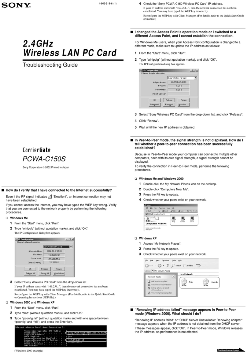
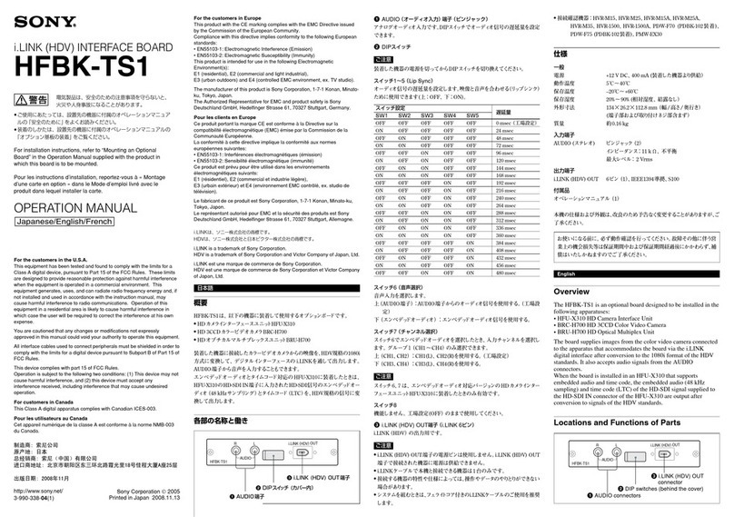
Sony SVT-RS1A User manual

3-858-944-01 (1)
警告
© 1996 by Sony Corporation
Computer
Interface Board
Operating Instructions
Mode d'emploi
Bedienungsanleitung
Manual de instrucciones
Istruzioni per l'uso
取扱説明書
SVT-RS1A
お買い上げいただき、ありがとうございます。
電気製品は安全のための注意事項を守らないと、
火災や人身事故になることがあります。
この取扱説明書には、事故を防ぐための重要な注意事項と製品の
取り扱いかたを示しています。この取扱説明書をよくお読みのう
え、製品を安全にお使いください。お読みになったあとは、いつ
でも見られるところに必ず保管してください。
J
EN
F
D
E
I

2
安全のために
設置 …………………………………………………………… 3
VTRへの取り付け ……………………………………… 3
コンピューターへの接続………………………………… 3
データ転送速度の設定…………………………………… 3
インターフェース仕様 ……………………………………… 3
9ピンコネクター仕様 …………………………………… 3
データ形式………………………………………………… 3
通信プロトコル…………………………………………… 3
コマンドテーブル …………………………………………… 4
コマンド解説 ………………………………………………… 5
コマンド操作の開始……………………………………… 5
VTR操作コマンド ……………………………………… 5
VTR設定コマンド ……………………………………… 6
メニュー設定コマンド…………………………………… 6
VTR情報収集コマンド ………………………………… 6
VTRからのリターンコマンド ………………………… 8
その他のコマンド………………………………………… 8
目次
警告表示の意味
この取扱説明書および製品では、次のような表示をしていま
す。表示の内容をよく理解してから本文をお読みください。
この表示の注意事項を守らないと、火災
や感電などにより死亡や大けがなど人身
事故につながることがあります。
注意を促す記号
行為を指示する記号
下記の注意を守らないと、火災や感電により死亡や大けがに
つながることがあります。
本基板はご自分で取り付けないでください。
本基板のVTRへの取り付けは、お買い上げ店またはソニー
のサービス窓口にご依頼ください。
本基板をご自分でVTRに取り付けないでください。万一、
ご自分で誤った取り付けをしたまま使いますと、火災、感電
の原因となることがあります。
警告
注意
強制
感電
火災
警告
強制

3
J
データ形式
モード :非同期
キャラクター長 :8ビット
データ転送速度 :1200、2400、4800、9600bps
(メニュー設定)
パリティチェック:なし
ストップビット :1ビット
通信プロトコル
通信は1バイト単位で行ないます。コンピューターが1バイ
ト送信した後、VTRから返ってくる返答を待って次のバイ
トを送信します。VTRの返答には1バイトのものだけではな
く、カウンター値のように6バイトのものもあります。
また、EJECTのように実行に時間のかかるコマンドでは、
VTRはコマンド受信直後に返答を返すほかに、動作の完了
時にも実行結果を示す返答を出します。
VTRへの取り付け
下図のようにコンピューターインターフェースボードを取り
付けます。
取り付けは、必ずお買い上げ点またはソニーのサービス窓口
にご依頼ください。
コンピューターへの接続
<1 SHOT SET>
FIELD 1
INTERVAL 1M
<CLOCK SET>
TIME ADJ 00:00
OPERATION OUT
<OTHER>
REPEAT MODE1
RS-232C 1200
設置
9ピンコネクター仕様
インターフェース仕様
ピン
番号
3
2
4
5
信号
TXD
RXD
DTR
GND
信号の方向
VTR→コンピューター
VTR←コンピューター
VTR→コンピューター
RS-232C端子 (9ピンD-SUB)
コンピューター
インターフェース
ボード
タイムラプスビデオ
裏面の目隠し
板を外す。
データ転送速度の設定
コンピューターとの接続後、VTRの<OTHER>画面でデー
タ転送速度を設定してください。
1VTRのメニューボタンを押して<OTHER>画面を表
示させる。
2シフト▼ボタンを押してRS-232Cの項目を点滅させ、録
画/再生スピード+または−ボタンを押してデータ転送速
度(1200、2400、4800、9600bps)を設定する。
3設定が終わったら、サーチボタンを押して通常画面に戻す。
9ピンD-SUBケーブル
(別売り) コンピューターへ
コネクター側面のみぞに
合わせて差し込む。
注)ケーブルはクロスケーブルを使ってください。
動作
送信データ
受信データ
通信可能
信号接地

4
0
1
2
3
4
5
6
7
8
9
A
B
C
D
E
F
C
REC CHECK
REC
コマンドテーブル
SVT-RS1Aを介して使用できるコマンドは下表のとおりです。
VTR本体に対応する機能がない場合は、コマンドを送信しても動作しません。
0
1
2
3
4
5
6
7
8
9
A
B
C
D
E
F
0
COMPLETION
ERROR
CASSETTE OUT
NOT TARGET
ALARM IN
ACK
NAK
8
7
MENU
POWER
ON/OFF
R/P SPEED
SET
6
TIMER ON/OFF
SHIFT z
SHIFT $
SET +/RP 4
SET –/RP $
SECURITY
LOCK ON
SECURITY
LOCK OFF
5
CLEAR
94
ENTER
CLEAR
ERROR
REV PLAY
STILL
3
0
1
2
3
4
5
6
7
8
9
PLAY
STOP
2
AUDIO/
SEARCH
1
A
EJECT
FF
REW
B
ALARM SEARCH
ALARM SCAN
T/D SEARCH
D
COUNT CODE
HEAD TIME
POWER ON TIME
T/L STATUS SENSE
STATUS SENSE
F
T/L TABLE ON
T/L TABLE OFF
REC/DUB
REQUEST
VCR INQUIRY
E
MENU RESET
COUNT RESET
COUNT MEMORY

5
J
コマンド解説
RXD
TXD FA CA 0A0A
RXD
TXD B0 32 33 40 AB 0A0A0A0A0A
コマンド操作の開始
コマンド操作を開始するには、ON (F6) コマンドを送りま
す。VTRはACK (0A) を返します。
コマンド操作を終了するOFF (F7) コマンドを送るまで、
VTRはコマンドを受付けます。
VTR操作コマンド
POWERON/OFF(7B)
VTRの電源をON/OFFします。
PLAY(3A)
再生
記録中に送るとRECCHECKモードになります。
STILL(4F)
一時停止
記録中に送るとRECPAUSE(記録一時停止)になります。
STOP(3F)
テープ走行停止
FF(AB)
早送り
再生中に送ると、LOCKEDCUEになります。
一時停止中に送ると、コマ送りになります。
サーチ/スキャンモード設定後に送ると、正方向にサーチ/
スキャンをします。
REW(AC)
巻戻し
再生中に送ると、LOCKEDREVIEWになります。
一時停止中に送ると、逆方向のコマ送りになります。
サーチ/スキャンモード設定後に送ると、逆方向にサーチ/
スキャンをします。
REVPLAY(4A)
通常速度で逆方向再生
TIMERON/OFF(60)
タイマー録画のON/OFF
SECURITYLOCKON(69)
セキュリティーロックON
SECURITYLOCKOFF(6A)
セキュリティーロックOFF
AUDIO/SEARCH(22)
12/24時間モードで再生中にこのコマンドを送ると、音声再
生をON/OFFします。
テープ停止中にこのコマンドを送ると、サーチまたはスキャ
ンモードになります。
メニュー画面表示中にこのコマンドを送ると、メニューを終
了します。
以上のコマンドを受信すると、VTRはACK (0A) を返しま
す。
EJECT(A3)
テープ取出し
VTRはコマンド受信時にACK (0A) を返し、テープ取出し
が完了するとCASSETTEOUT (03) を返します。
REC(CA)
録画
このコマンドを送る前にREC/DUBREQUEST (FA) を送
る必要があります。
ALARMSEARCH(B0)
テープ上の希望のアラーム点へのサーチモードとなります。
希望のアラーム点を入力後FF (AB) またはREW (AC) を送
ります。
(例)23点目を正方向でサーチする。
VTRは希望の点が見つかるとCOMPLETION (01) を返し
ます。希望の点が見つかる前にテープの終わりまたは先頭に
達するとNOTTARGET (05) を返します。
ALARMSCAN(B1)
アラーム録画点を順次5秒づつ再生するスキャンモードにな
ります。
正方向にスキャンする場合はこのコマンドのあとにFF (AB)
を、逆方向にスキャンする場合はREW (AC) を送ります。
RECCHECK(C1)
記録中に送ると、テープが3秒間だけ戻された後に2秒間だ
け再生されます。これにより記録が正しく行われたかどうか
を確認できます。再生後はふたたび記録状態に戻ります。

6
T/DSEARCH(B2)
指定した日時を検索するサーチモードになります。サーチす
る日、時を順に入力したあと、正方向にサーチする場合は
FF (AB) を、逆方向にサーチする場合はREW (AC) を送り
ます。
(例)16日15時を正方向にサーチする。
VTRは希望の点が見つかるとCOMPLETION (01) を返し
ます。希望の点が見つかる前にテープの終りまたは先頭に達
するとNOTTARGET (05) を返します。
VTR設定コマンド
R/PSPEEDSET(7E)
録画/再生スピードを直接設定します。
このコマンドのあとに直接数値コマンドを送ります。
(例)960時間に設定する
COUNTRESET(E2)
カウンターをリセットします。VTRはACK (0A) を返しま
す。
COUNTMEMORY(E3)
カウンターメモリーをON/OFFします。VTRはACK (0A)
を返します。巻き戻しまたは早送りでカウンターがメ0:
00:00モになると、テープが自動的に停止します。
メニュー設定コマンド
MENU(74)
メニュー画面に切り換えます。コマンドを送る度にメニュー
画面が順次切り換わります。
SHIFTz(63)
右の設定項目に移ります。
SHIFT$(64)
下の設定項目に移ります。
SET+/RP4(65)
SET−/RP$(66)
設定内容を変更します。
MENURESET(E1)
メニュー画面の設定をリセットします。
コマンド解説(つづき)
RXD
TXD
D3 30 32 393530
RXD
TXD D7 d2 d4 d5d3d1
RXD
TXD
B2 0A 31 36 31 35 40 AB 0A0A0A0A0A0A
RXD
TXD 7E 39 36 30 40 0A0A0A0A0A
VTR情報収集コマンド
COUNTCODE(D0)
このコマンドを送ると、VTRがカウンターの値を6バイトで
返します。
1桁目は30Hが"+"、31Hが"ー"を示します。
(例)ー1:56:32
VTRINQUIRY(FB)
接続機器がVTRかどうかを確認します。
VTRはACK (0A) を返します。
HEADTIME(D2)
このコマンドを送ると、VTRはヘッドの使用時間を5バイト
で返します。
VTRがメニュー画面を表示しているときは動作しません。
(例)00529H
POWERONTIME(D3)
このコマンドを送ると、VTRは電源のON時間を5バイトで
返します。
VTRがメニュー画面表示しているときは動作しません。
STATUSSENSE(D7)
このコマンドを送ると、VTRが動作状態を5バイトで返しま
す。(「STATUSSENSE(D7) ビット割り当て」参照)
STATUSSENSE(D7) ビット割り当て
・ 第1バイト
ビット7: 0
6: 0
5: 0
4: RECINHIBIT(記録出来ないテープが入って
いる、またはテープが入っていない)
3: CASSETTEOUT(テープが入っていない)
2: 0
1: 0
0: ERROR(複数バイトコマンドで2バイト目以
降が間違っている)
RXD
TXD D0 31 36
3531 33 32

7
J
T/LSTATUSSENSE(D6)
このコマンドを送ると、VTRがタイムラプスの状態を5バイ
トで返します。(「T/LSTATUSSENSE(D6)ビット割り当
て」参照)
T/LSTATUSSENSE(D6) ビット割り当て
・ 第1〜第3バイト
タイムラプスの録画再生スピード状態を示します。
第1バイト:スピードの1桁目
第2バイト:スピードの2桁目
第3バイト:スピードの3桁目
(例)960時間モードの場合
第1バイト:30
第2バイト:36
第3バイト:39
・ 第4バイト
ビット7: ALARMRECMODE(アラーム記録状態に
なっている)
6: 1SHOTRECMODEON(テープスピード
の設定が"000"になっている)
5: SERIESRECMODEON(メニュー内の
SERIESの設定が"Y"になっている)
4: TIMERRECMODEON(タイマー録画待機
状態になっている)
3: 0
2: 0
1: POWERON(電源がONになっている)
0: AUDIOON(オーディオ再生モードになって
いる)
・ 第2バイト
ビット7: 0
6: 0
5: 0
4: 0
3: WARNING(ウォーニングが出ている)
2: 0
1: 0
0: 0
・ 第3バイト
ビット7: 0
6: TIMERRECON(タイマー録画状態になって
いる)
5: COUNTERMEMORY(カウンターメモリー
がONになっている)
4: 0
3: 0
2: REPEATMODE(リピート録画モードになっ
ている)
1: 0
0: 0
・ 第4バイト
ビット7: PLAYMODE(プレイ状態になっている)
6: FFMODE(早送り状態になっている)
5: REWMODE(巻戻し状態になっている)
4: STOPMODE(停止状態になっている)
3: 0
2: EJECT(テープを取り出す動作をしている)
1: RECMODE(録画状態になっている)
0: 0
・ 第5バイト
ビット7: 0
6: 0
5: CUEMODE(早送り再生状態になっている)
4: REVIEWMODE(巻戻し再生状態になってい
る)
3: 0
2: 0
1: PAUSEMODE(録画一時停止状態になって
いる)
0: STILLMODE(再生一時停止状態になってい
る)
RXD
TXD D6 d2 d4 d5d3d1

8
コマンド解説(つづき)
その他のコマンド
REC/DUBREQUEST(FA)
RECまたはDUBコマンドを送る直前に、このコマンドを送
ります。
ENTER(40)
数値コマンドの終りを示します。
CLEARERROR(41)
複数バイトコマンドで、直前に入力した1バイトを消しま
す。
CLEAR(56)
複数バイトコマンドを取り消します。
・ 第5バイト
ビット7: MENUMODE(メニューモードになってい
る)
6: T/DSEARCHMODE(タイムデートサーチ
状態でテープが動いている)
5: T/DSEARCHSET(タイムデートサーチで日
時の指定を行なっている)
4: ALARMSCANMODE(アラームスキャン状
態でテープが動いている)
3: 0
2: ALARMSEARCHMODE(アラームサーチ
状態でテープが動いている)
1: ALARMSEARCHSET(アラームサーチで
サーチ点の指定を行っている)
0: 0
VTRからのリターンコマンド
ACK(0A)
VTRがコマンドを受付けたとき返します。
NAK(0B)
VTRがコマンドを受付けなかったとき返します。
COMPLETION(01)
サーチ/スキャンで指定した点に到達したとき返します。
NOTTARGET(05)
サーチ/スキャンで指定点が見つからずテープの終わりまた
は先頭に達したとき返します。
CASSETTEOUT(03)
カセットを取り出したとき返します。
ALARMIN(06)
アラーム入力があったとき返します。
ERROR(02)
複数バイトコマンドで2バイト目以降がエラーのとき返しま
す。

9
EN
Table of Contents
Installation....................................................................... 10
Installing onto the VCR.................................................10
Connecting to a Computer ...........................................10
Setting the Data Transfer Rate.....................................10
Interface Specifications ................................................. 11
9-Pin Connector............................................................ 11
Data Format..................................................................11
Communication Protocol ..............................................11
Table of Commands ....................................................... 12
Command Reference......................................................13
Command Operation ....................................................13
VCR Control Commands .............................................. 13
VCR Setup Commands ................................................ 14
Menu Setup Commands...............................................14
VCR Status Commands ............................................... 14
Return Commands........................................................15
Other Commands ......................................................... 15
Owner's Record
The model and serial number of your set are located on the
top. Record the serial number in the space provided
below. Refer to these numbers whenever you call upon
your Sony dealer regarding this product.
Model No. SVT-RS1A
Serial No.
For customers in the USA
WARNING
You are cautioned that any changes or modifications not
expressly approved in this manual could void your authority
to operate this equipment.
Note:
This equipment has been tested and found to comply with
the limits for a Class A digital device, pursuant to Part 15 of
the FCC Rules. These limits are designed to provide
reasonable protection against harmful interference when
the equipment is operated in a commercial environment.
This equipment generates, uses, and can radiate radio
frequency energy and, if not installed and used in
accordance with the instruction manual, may cause harmful
interference to radio communications. Operation of this
equipment in a residential area is likely to cause harmful
interference in which case the user will be required to
correct the interference at his own expense.
The shielded interface cable recommended in this manual
must be used with this equipment in order to comply with
the limits for a digital device pursuant to Subpart B of Part
15 of FCC Rules.
English
10
EN
Installing onto the VCR
Install the board as illustrated.
Note
To install this board, consult your supplier or Sony service
representative.
Connecting to a Computer
Connect to a computer as illustrated.
Interface cable to be connected to the RS-232C connector
must be shielded as follows.
Installation
Setting the Data Transfer Rate
After connecting to a computer, set the data transfer rate in
the <OTHER> menu.
1 Press the MENU button on the VCR to display the
<OTHER> menu.
2 Press the SHIFT $ button to flash “RS-232C”, and press
the REC/PLAY SPEED + or – button to set the data
transfer rate (1200, 2400, 4800, or 9600 bps).
3 Press the SEARCH button to return to the normal
screen.
<1 SHOT SET>
FIELD 1
INTERVAL 1M
<CLOCK SET>
TIME ADJ 00:00
OPERATION OUT
<OTHER>
REPEAT MODE1
RS-232C 1200
Align the grooves on
both sides of the
connector.
Time Lapse VCR
Remove the
blank plate. Computer
Interface Board
Outer shell
Shield
RS-232C connector
(9-pin D-SUB type)
9-pin D-SUB type cable (not supplied)
To a computer

11
EN
Use the cross cable for communication.
Data Format
Mode: asynchronous
Character length: 8 bits
Data transfer rate: 1200/2400/4800/9600 bps
(set with menu)
Parity check: None
Stop bit: 1 bit
Communication Protocol
Communication between the computer and the VCR is
carried out one byte at a time. The computer sends one
byte, waits for the VCR to respond, then sends the next
byte. The response from the VCR may not be a single byte
but may be comprised of several bytes, such as six bytes
for a counter value. For commands, such as EJECT, which
take time to be executed, the VCR returns a response on
receiving the command, then sends another response after
executing the command.
Signal flow
VCR to computer
Computer to VCR
VCR to computer
Function
Transmit data
Receive data
Data terminal Ready
Ground
Pin No.
3
2
4
5
Signal
TXD
RXD
DTR
GND
Interface Specifications
9-Pin Connector

12
EN
0
1
2
3
4
5
6
7
8
9
A
B
C
D
E
F
Table of Commands
Commands listed below are available only when the VCR is
equipped with the corresponding function.
0
1
2
3
4
5
6
7
8
9
A
B
C
D
E
F
0
COMPLETION
ERROR
CASSETTE OUT
NOT TARGET
ALARM IN
ACK
NAK
87
MENU
POWER
ON/OFF
R/P SPEED
SET
6
TIMER ON/OFF
SHIFT z
SHIFT $
SET +/RP 4
SET –/RP $
SECURITY
LOCK ON
SECURITY
LOCK OFF
5
CLEAR
94
ENTER
CLEAR
ERROR
REV PLAY
STILL
3
0
1
2
3
4
5
6
7
8
9
PLAY
STOP
2
AUDIO/
SEARCH
1
A
EJECT
FF
REW
D
COUNT CODE
HEAD TIME
POWER ON TIME
T/L STATUS SENSE
STATUS SENSE
F
T/L TABLE ON
T/L TABLE OFF
REC/DUB
REQUEST
VCR INQUIRY
E
MENU RESET
COUNT RESET
COUNT MEMORY
B
ALARM SEARCH
ALARM SCAN
C
REC CHECK
REC

13
EN
EJECT (A3)
Ejects the tape.
The VCR returns ACK (0A) as soon as it receives this
command, then returns CASSETTE OUT (03) after it ejects
the tape.
REC (CA)
Records.
Before sending this command, you need to send REC/DUB
REQUEST (FA).
ALARM SEARCH (B0)
Initiates search for a specific alarm point. Send this
command, then enter the alarm point (date, time) and send
FF (AB) to search forward or REW (AC) to search
backward.
eg: Search forward for alarm point 23
When the alarm point is located, the VCR returns
COMPLETION (01). If the tape comes to the end or
beginning without the alarm point being located, the VCR
returns NOT TARGET (05).
ALARM SCAN (B1)
Initiates scanning of alarm points (five seconds each).
Send this command, then send FF (AB) to scan forward or
REW (AC) to scan backward.
REC CHECK (C1)
When this command is sent while recording, tape is
rewound three seconds then played back two seconds. With
this operation, the VCR checks that the recording is correct.
After playback, the VCR returns to recording mode.
T/D SEARCH (B2)
Initiates search for a specific time/date. Send this
command, followed by the date and time then send FF (AB)
to search forward or REW (AC) to search backward.
eg: Search forward for the 16th, 15 o’clock.
When the time/date is located, the VCR returns
COMPLETION (01). If the tape comes to the end or
beginning without the time/date being located, the VCR
returns NOT TARGET (05).
Command Reference
Command Operation
To initiate command operation, send TL TABLE ON (F6).
The VCR will respond with ACK (0A).
The VCR will receive commands until you send TL TABLE
OFF (F7) to end command operations.
VCR Control Commands
POWER ON/OFF (7B)
Turns on/off the VCR.
PLAY (3A)
Plays back a tape.
When this command is sent while recording, the VCR enters
REC CHECK.
STILL (4F)
Pauses tape.
When this command is sent while recording, the VCR enters
REC PAUSE.
STOP(3F)
Stops tape.
FF (AB)
Fast forwards the tape.
When this command is sent while playing, the VCR enters
LOCKED CUE.
During pause, the VCR plays back still pictures.
During search/scan, the VCR switches to forward search/
scan.
REW (AC)
Rewinds the tape.
When this command is sent while playing, the VCR enters
LOCKED REVIEW.
During pause, the VCR plays back still pictures in reverse.
During search/scan, the VCR switches to reverse search/
scan.
REV PLAY (4A)
Plays back a tape in reverse at normal speed.
TIMER ON/OFF (60)
Switches on/off timer recording.
SECURITY LOCK ON (69)
Switches on security lock.
SECURITY LOCK OFF (6A)
Switches off security lock.
AUDIO/SEARCH (22)
When this command is sent while playing in the 12/24 hour
mode, the sound switches on/off.
During stop, the VCR enters SEARCH/SCAN mode.
When the menu is displayed, this command ends the menu.
When the VCR receives the commands above, the VCR
returns ACK (0A).
RXD
TXD FA CA 0A0A
RXD
TXD B0 32 33 40 AB 0A0A0A0A0A
RXD
TXD
B2 0A 31 36 31 35 40 AB 0A0A0A0A0A0A

14
EN
VCR Setup Commands
R/P SPEED SET (7E)
Sets the recording/ playing speed. Send this command,
then enter the speed.
eg: Setting the speed to 120h
COUNT RESET (E2)
Resets the counter. The VCR returns ACK (0A).
COUNT MEMORY (E3)
Switches on/off the counter memory. The VCR returns ACK
(0A).
When the memory is switched on, the tape being fast
forwarded or rewound stops automatically at the point of
counter “0:00:00”.
Menu Setup Commands
MENU (74)
Displays the menu. The menu screen changes each time
you send this command.
SHIFT z (63)
Shifts the cursor to the item on the right.
SHIFT $ (64)
Shifts the cursor to the item below.
SET +/RP 4 (65)
SET –/RP $ (66)
Changes the setting of the selected item.
MENU RESET (E1)
Resets menu settings.
VCR Status Commands
COUNT CODE (D0)
In response to this command, the VCR returns the counter
value (six bytes). “30H” indicates “+” and “31H” indicates
“–”.
eg: “–1 : 56 : 32”
VCR INQUIRY (FB)
Confirms that the connected equipment is a VCR. The VCR
returns ACK (0A).
HEAD TIME (D2)
In response to this command, the VCR returns the
operation time of the video heads. This command does not
function when the menu is displayed.
eg: “00529H”
RXD
TXD D7 d2 d4 d5d3d1
POWER ON TIME (D3)
In response to this command, the VCR returns the power on
time (five bytes). This command does not function when
the menu is displayed.
STATUS SENSE (D7)
In response to this command, the VCR returns its status
(five bytes). Refer to “STATUS SENSE bit allocation”
below.
STATUS SENSE bit allocation
• First byte
Bit 7: 0
6: 0
5: 0
4: REC INHIBIT; the tape cannot be recorded on or
no tape inserted
3: CASSETTE OUT; no tape
2: 0
1: 0
0: ERROR; error in byte data
• Second byte
Bit 7: 0
6: 0
5: 0
4: 0
3: WARNING; a warning is being issued
2: 0
1: 0
0: 0
• Third byte
Bit 7: 0
6: TIMER REC ON; the VCR is in timer recording
mode
5: COUNTER MEMORY; the counter memory is
switched on
4: 0
3: 0
2: REPEAT MODE; the VCR is in repeat recording
mode
1: 0
0: 0
• Fourth byte
Bit 7: PLAY MODE; the VCR is in playback mode
6: FF MODE; the VCR is in fast-forward mode
5: REW MODE; the VCR is in rewind mode
4: STOP MODE; the VCR is in stop mode
3: 0
2: EJECT; the VCR is ejecting a tape
1: REC MODE; the VCR is in recording mode
0: 0
Command Reference
RXD
TXD D0 31 36
3531 33 32
RXD
TXD
7E 31 32 30 40 0A0A0A0A0A
RXD
TXD D3 30 32 393530

15
EN
• Fifth byte
Bit 7: 0
6: 0
5: CUE MODE; the VCR is in forward search mode
4: REVIEW MODE; the VCR is in reverse search
mode
3: 0
2: 0
1: PAUSE MODE; the VCR is in recording pause
mode
0: STILL MODE; the VCR is in playback pause mode
T/L STATUS SENSE (D6)
In response to this command, the VCR returns the time
lapse status (five bytes). Refer to “T/L STATUS SENSE bit
allocation” below.
T/L STATUS SENSE bit allocation
• First, second, third bytes: Indicates the time lapse
recording/playback speed
Byte 1: Indicates the first digit
2: Indicates the second digit
3: Indicates the third digit
eg: 120-hour mode
Byte 1: 30
Byte 2: 32
Byte 3: 31
• Fourth byte
Bit 7: ALARM REC MODE; the VCR is in alarm recording
mode
6: 1 SHOT REC MODE ON; the tape speed is set to
“000”
5: SERIES REC MODE ON; SERIES is set to “Y” in
the menu
4: TIMER REC MODE ON; the VCR is in timer
recording standby mode
3: 0
2: 0
1: POWER ON; the VCR is switched on
0: AUDIO ON; the VCR is in audio playback mode
• Fifth byte
Bit 7: MENU MODE; the VCR is in menu mode
6: T/D SEARCH MODE; the VCR is searching for a
time/date
5: T/D SEARCH SET; specifying the time/date to
search
4: ALARM SCAN MODE; the VCR is scanning alarm
points
3: 0
2: ALARM SEARCH MODE; the VCR is searching for
an alarm point
1: ALARM SEARCH SET; specifying the alarm point
to search
0: 0
Return Commands
ACK (0A)
Acknowledges the command.
NAK (0B)
Rejects the command.
COMPLETION (01)
Notifies that a search/scan point has been located.
NOT TARGET (05)
Notifies that the tape has come to the end or beginning
without the search/scan point being located.
CASSETTE OUT (03)
Confirms that the cassette has been ejected.
ALARM IN (06)
Notifies that an alarm signal has been input.
ERROR (02)
Indicates an error in the second or following byte of a
multiple-byte command.
Other Commands
REC/DUB REQUEST (FA)
Send this command just before sending the REC or DUB
commands.
ENTER (40)
Send this command to indicate the end of a numeric
command.
CLEAR ERROR (41)
Clears the last byte entered of a multiple-byte command.
CLEAR (56)
Clears a multiple-byte command.
RXD
TXD D6 d2 d4 d5d3d1

16
F
Installation
Français
Table des matières
Installation....................................................................... 16
Installation sur le magnétoscope.................................. 16
Raccordement à un ordinateur..................................... 16
Réglage du débit de transfert des données .................17
Spécifications de l’interface.......................................... 17
Connecteur à 9 broches ...............................................17
Format des données..................................................... 17
Protocole de communication ........................................ 17
Remarque
Pour des explications sur les différentes instructions,
consultez le “Table of Commands” et les “Command
References” en anglais.
Alignez les rainures de
part et d’autre du
connecteur.
Magnétoscope à
intervalle variable
Enlevez le
cache. Carte d’interface
ordinateur
Connecteur RS-232C
(D-SUB à 9 broches) A un ordinateur
Câble D-SUB à 9 broches (non fourni)
Gaine extérieure
Blindage
Installation sur le magnétoscope
Installez la carte comme illustré
Remarque
Pour installer cette carte, consultez votre fournisseur ou un
centre de service après-vente Sony.
Raccordement à un ordinateur
Raccordez la carte à un ordinateur de la façon illustrée.
Le câble d’interface à raccorder au connecteur RS-232C
doit être blindé comme spécifié ci-après.

17
F
Format des données
Mode : asynchrone
Longueur de caractère : 8 bits
Débit de transfert des données :
1200/2400/4800/9600 bps
(réglé via le menu)
Contrôle de parité : non
Bit d’arrêt : 1 bit
Protocole de communication
La communication entre l’ordinateur et le magnétoscope se
fait un octet à la fois. Ainsi, l’ordinateur envoie un octet et
attend la réponse du magnétoscope avant d’envoyer l’octet
suivant. La réponse du magnétoscope peut ne pas être un
unique octet mais comprendre plusieurs octets, par
exemple six octets pour une valeur de comptage. Pour les
instructions telles que EJECT, dont l’exécution nécessite un
certain temps, le magnétoscope renvoie une réponse à la
réception de l’instruction et envoie ensuite une autre
réponse après avoir exécuté l’instruction.
Broche n°
3
2
4
5
Signal
TXD
RXD
DTR
GND
Function
Transmission
données
Réception
données
Terminal de
données prêt
Masse
Réglage du débit de transfert des
données
Après avoir effectué le raccordement à un ordinateur,
réglez le débit de transfert des données dans le menu
<OTHER>.
1 Appuyez sur la touche MENU du magnétoscope de
manière à afficher le menu <OTHER>.
2 Appuyez sur la touche SHIFT $ pour faire clignoter
l’indication “RS-232C” et appuyez sur la touche REC/
PLAY SPEED + ou - pour définir le débit de transfert
des données (1200, 2400, 4800 ou 9600 bps).
3 Appuyez sur la touche SEARCH pour revenir à l’écran
de départ.
Connecteur à 9 broches
Spécifications de
l’interface
Sens du signal
Du magnétoscope
à l’ordinateur
De l’ordinateur au
magnétoscope
Du magnétoscope
à l’ordinateur
Utilisez un câble croisé pour la communication.
<1 SHOT SET>
FIELD 1
INTERVAL 1M
<CLOCK SET>
TIME ADJ 00:00
OPERATION OUT
<OTHER>
REPEAT MODE1
RS-232C 1200

18
D
Inhalt
Installation....................................................................... 18
Installation im Videorecorder........................................ 18
Anschließen an einen Computer .................................. 18
Einstellen der Datenübertragungsrate .........................19
Schnittstellenspezifikationen........................................ 19
9poliger Anschluß......................................................... 19
Datenformat ..................................................................19
Kommunikationsprotokoll .............................................19
Hinweis
Eine Erläuterung der Befehle finden Sie in der “Table of
Commands” und der “Command Reference” (Englisch).
Installation im Videorecorder
Installieren Sie die Karte, wie auf der Abbildung angegeben.
Hinweis
Ziehen Sie bei der Installation dieser Karte bitte Ihren
Händler oder den Sony-Kundendienst hinzu.
Anschließen an einen Computer
Nehmen Sie den Anschluß an den Computer wie auf der
Abbildung zu sehen vor.
Das Schnittstellenkabel, das mit dem RS-232C-Anschluß
verbunden werden soll, muß folgendermaßen abgeschirmt
sein.
Installation
Deutsch
Richten Sie die
Einkerbungen an beiden
Seiten des Anschlusses
aneinander aus.
Zeitraffer-Videorecorder
Nehmen Sie die
leere Platte
heraus.
Computer-
Schnittstellenkarte
RS-232C-Anschluß (9poliger
D-SUB-Anschluß) an einen Computer
9poliges D-SUB-Kabel (nicht mitgeliefert)
Äußerer Mantel
Abschirmung

19
D
Datenformat
Modus: asynchron
Zeichenlänge: 8 Bit
Datenübertragungsrate:
1200/2400/4800/9600 Bit/s (einzustellen
über das Menü)
Paritätsprüfung: keine
Stopbit: 1
Kommunikationsprotokoll
Bei der Kommunikation zwischen Computer und
Videorecorder wird jeweils 1 Byte übertragen. Das heißt,
der Computer sendet ein Byte, wartet auf eine Antwort des
Videorecorders und sendet dann das nächste Byte. Die
Antwort des Videorecorders kann jedoch aus mehreren
Bytes bestehen, zum Beispiel aus sechs Bytes, die einen
Zählerwert angeben. Bei Befehlen wie zum Beispiel EJECT,
die zur Ausführung etwas Zeit brauchen, sendet der
Videorecorder eine Antwort, sobald er den Befehl empfängt,
und eine weitere Antwort, nachdem er den Befehl
ausgeführt hat.
Stift
3
2
4
5
Signal
TXD
RXD
DTR
GND
Funktion
Transmit Data
(Daten übertragen)
Receive Data
(Daten empfangen)
Data Terminal
Ready
(Datenterminal
bereit)
Ground (Masse)
Einstellen der Datenübertragungsrate
Nachdem Sie die Verbindung zum Computer hergestellt
haben, müssen Sie noch die Datenübertragungsrate
einstellen, und zwar im Menü <OTHER>.
1 Drücken Sie die Taste MENU am Videorecorder, so daß
das Menü <OTHER> angezeigt wird.
2 Drücken Sie die Taste SHIFT $, so daß “RS-232C” zu
blinken beginnt. Dann stellen Sie mit der Taste REC/
PLAY SPEED + oder - die Datenübertragungsrate
(1200, 2400, 4800 oder 9600 Bit/s) ein.
3 Danach drücken Sie die Taste SEARCH. Die normale
Anzeige erscheint wieder.
9poliger Anschluß
Signalfluß
Vom Videorecorder
zum Computer
Vom Computer zum
Videorecorder
Vom Videorecorder
zum Computer
Schnittstellen-
spezifikationen
Verwenden Sie zur Kommunikation das Überkreuzungskabel.
<1 SHOT SET>
FIELD 1
INTERVAL 1M
<CLOCK SET>
TIME ADJ 00:00
OPERATION OUT
<OTHER>
REPEAT MODE1
RS-232C 1200

20
E
Indice
Instalación....................................................................... 20
Instalación en la videograbadora ................................20
Conexión a un ordenador............................................ 20
Ajuste del índice de transferencia de datos................ 21
Especificaciones de interfaz ......................................... 21
Conector de 9 pines .................................................... 21
Formato de datos ........................................................ 21
Protocolo de comunicación .........................................21
Nota
Para obtener información sobre los comandos, consulte
“Tabla de comandos” y “Referencia de comandos” en
inglés.
Instalación en la videograbadora
Instale la tarjeta como se muestra en la ilustración.
Nota
Para instalar esta tarjeta, consulte a su proveedor o técnico
de servicio Sony.
Conexión a un ordenador
Realice la conexión como se muestra en la ilustración.
El cable de interfaz que vaya a conectar al conector RS-
232C debe estar reforzado como se muestra a
continuación.
Instalación
Español
Videograbadora de muy
baja frecuencia
Retire la placa
sin información. Tarjeta de interfaz
de ordenador
Alinee las ranuras en
ambos lados del
conector.
Conector RS-232C
(tipo D-SUB de 9 pines)
Cable de tipo D-SUB de 9 pines
(no suministrado)
A un ordenador
Refuerzo exterior
Protección
Table of contents
Other Sony Computer Hardware manuals

Sony
Sony PCWA-C100 User manual

Sony
Sony HFBK-SD1 User manual

Sony
Sony DP-IF5100 User manual

Sony
Sony PCWA-C700 - Wireless Lan Dual Pc Card User manual

Sony
Sony BKDS-2530 User manual

Sony
Sony HKSR-5803HQ User manual

Sony
Sony PCWA-C150S - Wireless Lan Pc Card Instruction sheet

Sony
Sony DPS-V55M User manual

Sony
Sony ESBK-7051 User manual

Sony
Sony HR-MPS User manual

Sony
Sony PDBK-201 Quick start guide

Sony
Sony SDP-EP90ES User manual

Sony
Sony MPE-200 User manual

Sony
Sony HFBK-XG1 User manual

Sony
Sony BKMW-E3000 User manual

Sony
Sony SDP-E800 User manual

Sony
Sony VAIO PCWA-C800S Instruction sheet

Sony
Sony MSAC-PR1 User manual

Sony
Sony PCWA-C800S Read This First User manual

Sony
Sony IFB-X600E User manual