Metrohm 853 CO2 Suppressor User manual

853 CO2Suppressor
Manual
8.853.8001EN


Metrohm AG
CH-9101 Herisau
Schweiz
Telefon +41 71 353 85 85
Fax +41 71 353 89 01
www.metrohm.com
853 CO2 Suppressor
Manual
8.853.8001EN 04.2008 / zst

Teachware
Metrohm AG
Oberdorfstrasse 68
CH-9101 Herisau
teachware@metrohm.com
These instructions are protected by copyright. All rights reserved.
Although all the information given in these instructions has been checked
with great care, errors cannot be entirely excluded. Should you notice any
mistakes please inform the author at the address given above

Table of contents
853 CO2Suppressor / Instructions for Use 8.853.8001EN
I
Table of contents
1Introduction.................................................... 1
1.1 Instrument description ............................................................. 1
1.2 Parts and controls .................................................................... 2
1.2.1 Front view 853 CO2Suppressor....................................................2
1.2.2 Rear view 853 CO2Suppressor ....................................................3
1.3 Information on the Instructions for Use .................................. 4
1.3.1 Organization ..................................................................................4
1.3.2 Notation and pictograms ..............................................................5
1.4 Safety information..................................................................... 6
1.4.1 Electrical safety..............................................................................6
1.4.2 General safety rules.......................................................................6
2Installation ..................................................... 7
2.1 Instrument setup....................................................................... 7
2.1.1 Packaging......................................................................................7
2.1.2 Checks...........................................................................................7
2.1.3 Arranging the instruments .............................................................7
2.2 Mains connection...................................................................... 7
2.3 Connection to the 861 Advanced Compact IC ........................ 8
2.4 Connection to 830 IC Interface ................................................ 9
2.5 Connection of capillaries ....................................................... 10
2.6 Cartridges................................................................................ 10
3Operation...................................................... 11
3.1 General information................................................................ 11
3.2 Control..................................................................................... 11
3.2.1 Control via 861 Advanced Compact IC (2.861.0040).................11
3.2.2 Control via 830 IC Interface.........................................................11
4Troubleshooting - Problems......................... 12
4.1 Remedying faults and problems ............................................ 12
4.2 Chromatography problems .................................................... 12
4.3 Instrument problems .............................................................. 13
4.4 Care and maintenance............................................................ 13
4.4.1 Care .............................................................................................13
4.4.2 Maintenance by Metrohm Service ..............................................14
4.4.3 CO2Absorber Cartridge replacement.........................................14
4.4.4 H2O Absorber Cartridge regeneration ........................................14
5Appendix ....................................................... 15
5.1 Technical data......................................................................... 15
5.2 Standard equipment ............................................................... 17
5.2.1 2.853.0010 CO2Suppressor .......................................................17
5.3 Optional accessories.............................................................. 18
5.4 Validation / GLP ...................................................................... 19
5.5 Warranty and Conformity ....................................................... 20
5.5.1 Warranty.......................................................................................20
5.5.2 Declaration of Conformity ...........................................................21
5.5.3 Quality Management Principles ..................................................22

Table of contents
853 CO2Suppressor / Instructions for Use 8.853.8001EN
II
5.5.4 Index............................................................................................ 23
List of illustrations
Figure 1: Front view 853 CO2Suppressor .................................................... 2
Figure 2: Rear view 853 CO2Suppressor..................................................... 3
Figure 3: Connection between 853 CO2Suppressor and 861 Advanced
Compact IC ................................................................................... 8
Figure 4: Connection between the 853 CO2Suppressor and 830 IC
Interface......................................................................................... 9

1.1 Instrument description
853 CO2Suppressor / Instructions for Use 8.853.8001EN
1
1 Introduction
1.1 Instrument description
The 853 CO2Suppressor is used to remove CO2before detection
takes place. CO2can enter the eluent flow from the sample itself, or is
produced by the suppressor reaction (see below, Reaction in the sup-
pressor module «MSM II»).
If the 853 CO2Suppressors is connected between the suppressor mo-
dule «MSM II» and the detector block the CO2peak is effectively mini-
mized. The principle is based on the permeability of the Teflon AFTM
membrane in the degassing cell of the 853 CO2Suppressor to gases.
The eluent (together with the injected sample) passes through a capil-
lary with a Teflon AFTM membrane contained in the degassing cell, in
which a vacuum has been created by a pump. At the same time the
pump draws CO2-free air (the CO2is removed by the CO2Absorber
Cartridge) through the degassing cell. The lower CO2vapor pressure in
the degassing cell compared with that in the capillary results in the dif-
fusion of CO2from the eluent flow. The pump of the 853 CO2Suppres-
sors is provided with electricity from an external power supply. The 853
CO2Suppressor is controlled by Remote commands.
Reaction in the suppressor module «MSM II»
If a carbonate eluent is used then the following reaction (among others)
takes place in the suppressor module «MSM II»:
R-SO3
-H++ NaHCO3/Na2CO3→R-SO3
-Na++ H2O + CO2
1 Introduction
853 CO2Suppressor / Instructions for Use 8.853.8001EN
2
1.2 Parts and controls
In this section you will find the numbers and designations of the parts
and controls of the 853 CO2Suppressor. The numbering applies
throughout the instructions for use, i.e. bold numbers in the text (e.g.
3
) refer to the parts and controls illustrated here.
1.2.1 Front view 853 CO2Suppressor
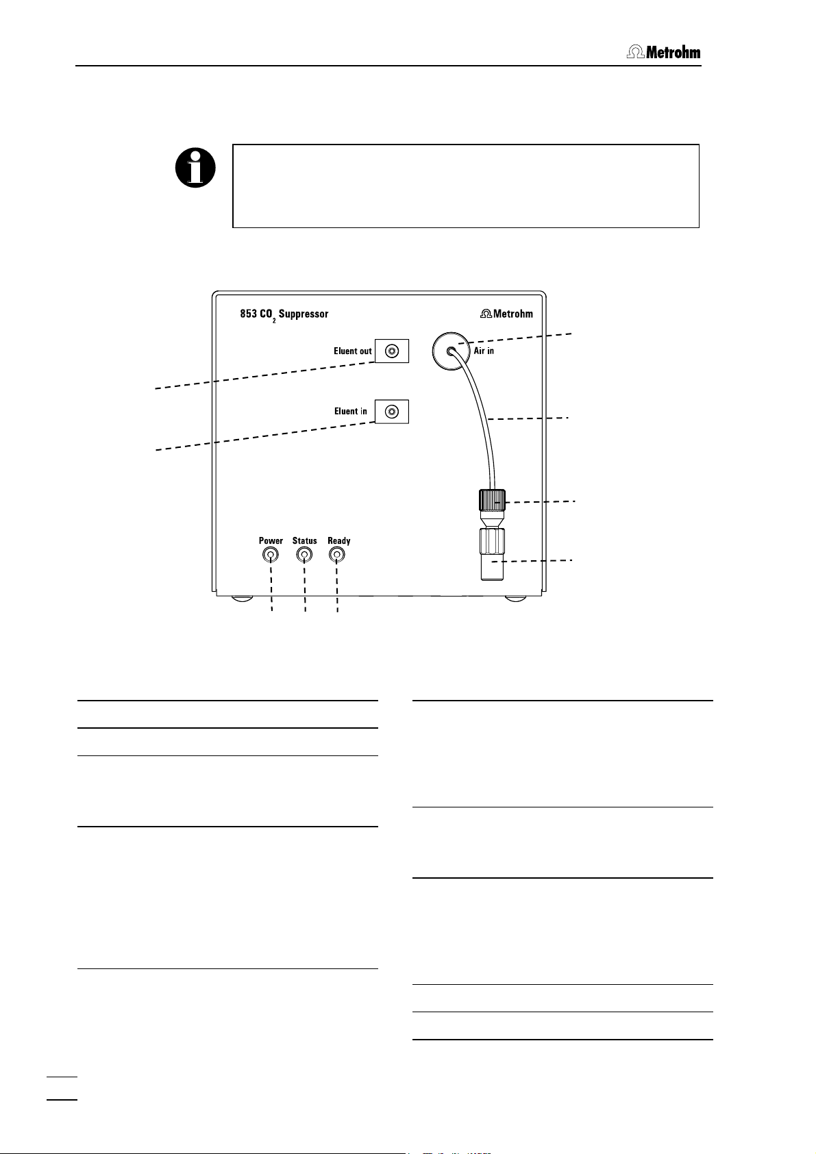
Figure 1: Front view 853 CO2Suppressor
1Eluent flow outlet "Eluent out"
2Eluent flow inlet "Eluent in"
3LED "Power"
Lights up green when the pump is run-
ning.
4LED "Status"
Lights up orange when the pump is
running and the pressure in the vacu-
um chamber is too high or too low.
After the pump has been switched on it
takes a few seconds for the vacuum to
be established.
5LED "Ready"
Lights up green when the pump is run-
ning and the pressure in the vacuum
chamber is within the ideal working
range.
6Aspiration opening "Air in"
Opening for drawing in CO2-free air
(through CO2Absorber Cartridge).
7PEEK flow reduction capillary
6.1831.130
The length of the flow reduction capilla-
ry provides an optimal flow and should
not be altered.
8Pressure screw
9Coupling
6
7
8
9
1
2
5
4
3

1.2 Parts and controls
853 CO2Suppressor / Instructions for Use 8.853.8001EN
3
1.2.2 Rear view 853 CO2Suppressor
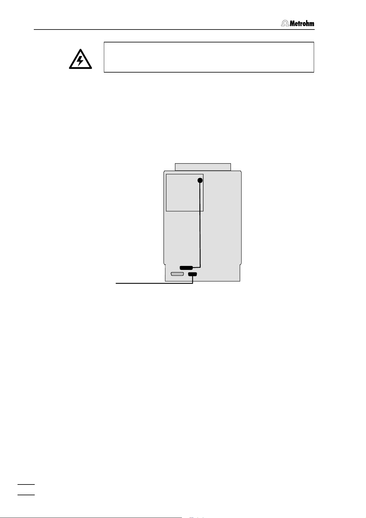
Figure 2: Rear view 853 CO2Suppressor
10 Exhaust opening "Exhaust"
Air is pumped out of the degassing cell
through this opening.
11 15V Mains connection "15V DC"
12 Remote interface "Remote"
For remote control by external devices.
10
11 12
1 Introduction
853 CO2Suppressor / Instructions for Use 8.853.8001EN
4
1.3 Information on the Instructions for Use
Please read through these Instructions for Use carefully before you put
the 853 CO2Suppressor into operation. The Instructions for Use con-
tain information and warnings to which the user must pay attention in
order to assure safe operation of the instrument.
1.3.1 Organization
These Instructions for Use 8.853.8001EN for the 853 CO2Supp-
ressor provide a comprehensive overview of installation, startup proce-
dure, operation, fault rectification and technical specifications of this in-
strument. The Instructions for Use are organized as follows:
Section 1 Introduction
General description of instrument, parts and controls
and safety notes
Section 2 Installation
Installation and connection of the instrument, of the
accessories and of the software
Section 3 Operation
Introduction to the operation.
Section 4 Troubleshooting - Problems
Possible faults and their remedies.
Section 5 Appendix
Technical data, standard equipment, optional acces-
sories, validation, warranty and declaration of con-
formity, index
In order to find the information you require about the 853 CO2Supp-
ressor you should either use the Contents or the Index.

1.3 Information on the Instructions for Use
853 CO2Suppressor / Instructions for Use 8.853.8001EN
5
1.3.2 Notation and pictograms
The following notation and pictograms (symbols) are used in these In-
structions:
10 Part or control
Danger/Warning
This symbol indicates a possible
risk of death or injury to the user
and possible damage to the
instrument or its components by
electric current.
Danger/Warning
This symbol indicates a possible
risk of death or injury to the user
and possible damage to the in-
strument or its components.
Attention
This symbol indicates important in-
formation that you should read be-
fore continuing.
Information
This symbol indicates additional in-
formation and tips which may be of
particular use to you.

1 Introduction
853 CO2Suppressor / Instructions for Use 8.853.8001EN
6
1.4 Safety information
1.4.1 Electrical safety
Electrical safety when handling the 853 CO2Suppressor is guaranteed
within the scope of Standard IEC 1010-1 (protection class III, protection
code IP20). The following points must be observed:
• Mains connection
The mains connection must be made in accordance with the in-
structions given in Section 2.2.
• Opening the instrument
The housing contains no components which could be set or adjusted
by the user .
The instrument should only be opened by specialists from Metrohm. If
the 853 CO2Suppressor is connected to the mains supply it should
neither be opened nor should components be removed from it, as
otherwise there is a risk of coming into contact with current-carrying
components. Before opening the instrument always make sure that
the plug has been pulled out!
• Protection against electrostatic charges
Electronic components are sensitive to electrostatic charges and can
be destroyed by a discharge. Before you touch any electronic com-
ponents of the 853 CO2Suppressor you should ground you and your
tools by grasping a grounded object (e.g. the instrument housing or a
radiator) in order to eliminate any electrostatic charges that may be
present.
1.4.2 General safety rules
• Solvent handling
Check the pump tubing and inlet and outlet connections for leaks at
regular intervals. Observe the relevant regulations when handling and
disposing of flammable and/or toxic solutions.
2.1 Instrument setup
853 CO2Suppressor / Instructions for Use 8.853.8001EN
7
2 Installation
2.1 Instrument setup
2.1.1 Packaging
The 853 CO2Suppressor and its separately packed accessories are
supplied in very protective special packaging. Please store all this spe-
cial packaging; it is the only way in which the safe transport of the
instrument can be guaranteed.
2.1.2 Checks
Please check that the delivery is complete and undamaged immediate-
ly on receipt (compare with delivery note and list of accessories given in
Section 5.2). If transport damage is evident please refer to the informati-
on given in Section 5.5.1 "Warranty".
2.1.3 Arranging the instruments
Place the 853 CO2Suppressor next to the detector block in the Com-
pact IC. With a modular system, place it in the Separation Center, like-
wise next to the detector block.
2.2 Mains connection
The 853 CO2Suppressor is provided with a 15 V power supply from an
external power supply (6.2152.020).
1 Connection 853 – Power supply
• Connect the external power supply (6.2152.020) to the 15V
connection "15V DC" of the 853 CO2Suppressor.
2 Mains connection
• Plug the mains cable into the connection on the external power
supply (6.2152.020), and connect it to the mains supply (100-
240 V).
Mains cable
The instrument is supplied with one of the following mains cables
• 6.2122.020 with SEV 12 plug (Switzerland, …)
• 6.2122.040 with CEE(7), VII plug (Germany, …)
• 6.2133.070 with NEMA 5-15 plug (USA, …)
which has three wires and is fitted with a plug with a grounding pin. If a
different plug has to be used then the yellow/green wire (IEC standard)
must be connected to the grounding pin (Protection class I).
2 Installation
853 CO2Suppressor / Instructions for Use 8.853.8001EN
8
Make sure that the power supply is always in a dry location. Protect it
against direct contact with liquids.
2.3 Connection to the 861 Advanced Compact IC
The 853 CO2Suppressor is part of the version 2.861.0040 of the 861
Advanced Compact IC.
The electrical connections of the system, consisting of the 861 Ad-
vanced Compact IC and 853 CO2Suppressor, are shown in the follow-
ing diagram:
Figure 3: Connection between 853 CO2Suppressor and 861 Ad-
vanced Compact IC
The 853 CO2Suppressor can be controlled by the system driver of the
861 (Version 2.861.0040) in the PC program «IC Net» (from Version 2.3
SR2) (see «IC Net» Instructions for Use, Section 6.27).
861
853
PC 6.2134.100
6.2143.230

2.4 Connection to 830 IC Interface
853 CO2Suppressor / Instructions for Use 8.853.8001EN
9
2.4 Connection to 830 IC Interface
Connect an Event line of the 830 IC Interface to the remote interface 12
of the 853 CO2Suppressor using a cable 6.2128.180.
Figure 4: Connection between the 853 CO2Suppressor and 830
IC Interface
In the PC program «IC Net» the 853 CO2Suppressor does not have its
own device driver. It can be controlled via the 830 IC Interface. This
means that the 830 IC Interface must be included in your system and
configured for controlling the 853 CO2Suppressor:
1 Open «IC Net» system
• In the PC program «IC Net» open the system in which the 830
IC Interface is to be included.
2 Include the 830 IC Interface in the system
• Use Setup/New devices/Link to existing device to select
the 830 IC Interface (the 830 IC Interface must already have
previously been added to the "Workplace", see IC Net
Instructions for Use, Section 5). The device symbol for the 830
IC Interfaces is added to the system.
3 Open the "Events setup" tab
• Double-click on the device symbol of the 830 IC Interfaces to
open its configuration menu and select the Events setup tab.
4 Set the control line for the 853 CO2Suppressor
• The value for the Event line used to control the 853 CO2
Suppressor must be set to 1. In the example shown above this
is Event Line 1, see Figure 4.
The 853 CO2Suppressor has now been included in your system and
can be controlled by the PC program «IC Net». It is started together
with the other system hardware with System/Control/Startup hard-
ware and closed down with System/Control/Shutdown hardware.
6.2128.180
816
853
830

2 Installation
853 CO2Suppressor / Instructions for Use 8.853.8001EN
10
2.5 Connection of capillaries
The 853 CO2Suppressor is connected between the suppressor module
«MSM II» and the detector block.
1 Suppressor module «MSM II» – 853 CO2Suppressor
• Connect the "Suppressor outlet capillary for eluent" (marked
with "Detector") to the "Eluent in"inlet (2) of the 853 CO2
Suppressor using a 6.2744.010 Pressure screw.
2 853 CO2Suppressor – Detector block
• Connect the "Inlet capillary to detector block" to the "Eluent
out"outlet (1) of the 853 CO2Suppressor using a 6.2744.010
Pressure screw.
2.6 Cartridges
Effective CO2removal requires that the air pumped through the de-
gassing cell should contain as little CO2as possible. This is achieved
by drawing the air through a 6.2837.000 CO2Absorber Cartridge.
The CO2Absorber Cartridge can become blocked by moisture. This
can be prevented by connecting a 6.2837.010 H2O Absorber Car-
tridge in front of it.
The cartridges are installed as follows:
1 Remove caps
• Remove the sealing caps at the inlet and outlet of each
cartridge.
2 Connect CO2Absorber Cartridge
• Insert the CO2Absorber Cartridge (3-layer filling, blue-brown-
gray) in the coupling 9.
3 Connect H2O Cartridge – CO2Cartridge
• Insert the 6.1808.190 Adapter in the CO2Absorber Cartridge.
• Attach the 6.1801.140 PVC tubing to the 6.1808.190 Adapter.
• Insert the H2O Absorber Cartridge (filled with orange drying
beads) into the 6.1801.140 PVC tubing.
4 Attach the cartridges
• Attach the two cartridges to the left-hand mounting support of
the 861 Advanced Compact IC or 820 IC Separation Center
using two 6.2027.070 Holders.

3.1 General information
853 CO2Suppressor / Instructions for Use 8.853.8001EN
11
3 Operation
3.1 General information
• The pump has two operating stages. The first stage is used to cre-
ate the vacuum, the second stage to maintain it.
• The Power display lights up green when the pump is switched on.
• The Status display lights up orange when the pump is running and
the pressure in the vacuum chamber is either too low or too high.
After the pump has been switched on it takes a few seconds for the
vacuum to become established.
• The Ready display lights up green when the pump is running and
the pressure in the vacuum chamber is within the working range.
3.2 Control
The 853 CO2Suppressor is controlled by the PC program «IC Net». It is
not included in the software as a separate device driver, but is con-
trolled from other devices via a Remote line.
3.2.1 Control via 861 Advanced Compact IC (2.861.0040)
The 853 CO2Suppressor is included in the device driver of Version
2.861.0040 of the 861 Advanced Compact IC. Detailed information is
provided in the «IC Net» Instructions for Use, Section 6.27.
3.2.2 Control via 830 IC Interface
If the 853 CO2Suppressor is used together with a modular system then
it can be controlled via a Remote line of the 830 IC Interface (see Sec-
tion 2.4).

4 Troubleshooting - Problems
853 CO2Suppressor / Instructions for Use 8.853.8001EN
12
4 Troubleshooting - Problems
4.1 Remedying faults and problems
If difficulties occur during analyses with your IC system then it is best to
search for their causes in the following sequence: column →pump →
eluent →IC system. In the Instructions for Use of your Modular IC
system or Compact IC you will find an overview of possible faults to-
gether with their causes and remedies.
In addition to these general problems, the following section covers
those problems which could arise from the use of the 853 CO2Supp-
ressor.
4.2 Chromatography problems
Problem Cause Remedy
Poor retention time
reproducibility
• Leak in the instrument.
• Blockage in flow path.
• Contact Metrohm Service.
• Check the capillary connections
and replace any compressed
capillaries
Noisy or unstable
baseline
• Leak in the instrument.
• Blockage in flow path
• CO2cartridge exhausted
• Vacuum pump faulty
• Contact Metrohm Service.
• Check the capillary connections
and replace any compressed
capillaries
• Replace CO2 cartridge (see Sec-
tion 4.4.3)
• Contact Metrohm Service.
High pressure in the
system
• Pressure screws
tightened up too far.
• A liquid-transporting
component in the device
is blocked.
• Loosen pressure screws slightly
or replace connection (cut new
capillary end)
• Contact Metrohm Service.
Poor peak shape • Dead volume in system
• Check capillaries

4.3 Instrument problems
853 CO2Suppressor / Instructions for Use 8.853.8001EN
13
4.3 Instrument problems
Problem Cause Remedy
LED "Power"(1) does
not light up when in-
strument is switched
on.
• Power supply not con-
nected
• 6.2152.020 Power sup-
ply faulty or electronics
fault in 853 CO2Suppres-
sor
• Connect the 853 CO2Suppres-
sor to the mains supply via the
external power supply (see
Section 2.2)
• Contact Metrohm Service.
Neither LED "Status"
(2) nor LED "Ready"
(3) lights up when in-
strument is switched on
(LED "Power"(1) lights
up).
• LEDs faulty • Contact Metrohm Service.
Vacuum out of working
range. LED "Ready"(3)
does not light up after
instrument has been
switched on for at least
30 s.
• Leak in system (vacuum
too weak)
• H2O Absorber Cartridge
blocked (vacuum too
strong).
• Contact Metrohm Service.
• Regenerate the H2O Absorber
Cartridge (see Section 4.4.4
or 8.108.1046 Leaflet)
4.4 Care and maintenance
4.4.1 Care
The 853 CO2Suppressor requires adequate care. If it becomes excessi-
vely dirty then this could interfere with its functions and shorten the
working life of its robust mechanism and electronics.
Spilt chemicals and solvents must be wiped up immediately. The elec-
trical connections on the rear panel of the instrument (the mains con-
nection in particular) should be protected against contamination.
Although constructive measures to a large extent prevent liquid pene-
tration, if aggressive media should nevertheless penetrate the interior
of the instrument then the mains plug of the external 6.2152.020
Power supply should be pulled out immediately to prevent serious
damage to electronic components. If such damage should occur
please contact Metrohm Service.
The instrument should only be opened by specialists from Metrohm.

4 Troubleshooting - Problems
853 CO2Suppressor / Instructions for Use 8.853.8001EN
14
4.4.2 Maintenance by Metrohm Service
It is advisable to carry out the maintenance of the 853 CO2Suppressor
within the framework of an annual service visit by trained Metrohm
technicians. If aggressive and corrosive chemicals are used then it may
be necessary to reduce the service intervals.
The Metrohm Service Department will be pleased to provide you with
competent advice about the care and maintenance of all Metrohm in-
struments at any time.
4.4.3 CO2Absorber Cartridge replacement
The 6.2837.000 CO2Absorber Cartridge requires replacement at regu-
lar intervals because of blockages or exhaustion.
Blockages
Moisture will block the CO2Absorber Cartridge. This is indicated by the
cartridge material changing color (the blue layer turns violet). The air
flow is reduced and the vacuum becomes too low – instead of the
"Ready" LED (3) the "Status" LED (2) lights up. In order to protect the
CO2Absorber Cartridge an H2O Absorber Cartridge is included up-
stream from it. Regular regeneration (see Section 4.4.4) of the H2O Ab-
sorber Cartridge increases the working life of the CO2Absorber Car-
tridge.
Exhaustion
The absorption capacity of the CO2Absorber Cartridge is limited. De-
pending on the working life and the laboratory surroundings the ab-
sorption capacity decreases with time. This is indicated by a rising
baseline (as more CO2reaches the detector).
4.4.4 H2O Absorber Cartridge regeneration
The purpose of the H2O Absorber Cartridge is to protect the CO2Ab-
sorber Cartridge from moisture. The lifespan of the H2O Absorber Car-
tridge depends on the humidity of the ambient air. Humidity exhausts
the H2O Absorber Cartridge. Exhaustion is indicated by a color change:
before the color of the whole of the filling material has changed (from
orange to colorless) the H2O Absorber Cartridge must be regenerated
(see 8.108.1046 Leaflet). Regeneration consists of replacing the filling
material:
1. Heat the loose material (i.e. not in the cartridge) at 140 °C over-
night and then refill it, or dispose of the old material and refill the
cartridge with new material (Fluka # 94098).
2. Cover the packed material with absorbent cotton.
Table of contents


