New Cosmos Electric KD-12B User manual
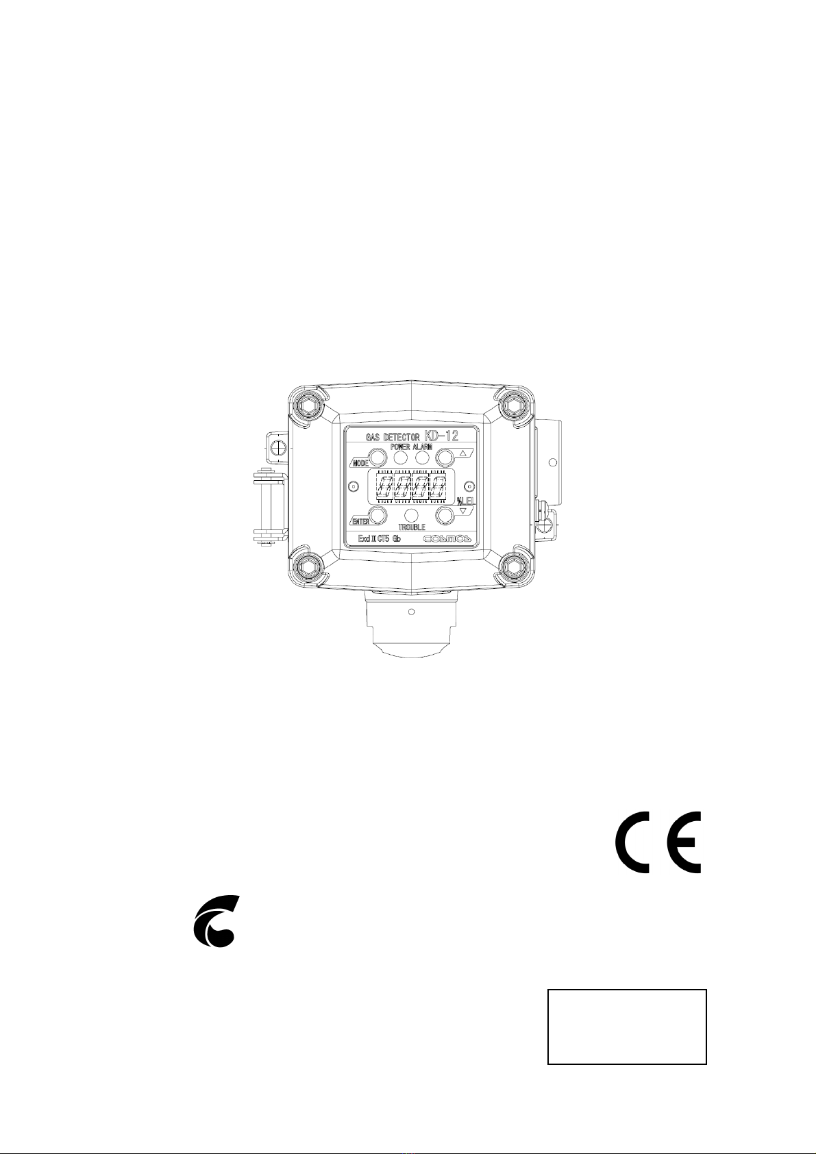
Diffusion type Gas Detector
Model KD-12B
(SIL2 Capable)
Instruction Manual
Keep this instruction manual where it is readily accessible.
Thoroughly read this instruction manual before using the equipment so it can be used
safely and correctly.
This manual provides information concerning standard specifications. If the specifications
of your model are nonstandard, refer to the delivery specifications.
Instruction Manual No.
GAE-054-00
July 2014
New Cosmos Electric Co., Ltd.
Nomenclature
See pages 4 to 6.
Replacement of Sensor Unit
See pages 31 and 32.
Wiring and Connecting
Methods
See pages 14 to 16.
Ground terminals
24 V
power
supply
Indicator
E.g., External
alarm
Shield
Display and Operation in
Each Mode
See page 19.
Maintenance Check and
Operation Methods
See pages 22 to 30.
Troubleshooting
See page 33.

Table of Contents
1. Introduction ..................................................................................................................1
2. Precautions..................................................................................................................2
3. Contents of Package .................................................................................................... 3
4. External Dimensions and Nomenclature......................................................................4
4-1. Main Unit ................................................................................................................4
4-2. Display and Control Blocks..................................................................................... 5
4-3. Terminal Block ........................................................................................................ 6
5. Installation....................................................................................................................7
5-1. Installation Method .................................................................................................7
5-2. Examples of Installation Positions ........................................................................ 11
5-3. Mounting of Optional items................................................................................... 12
6. Wiring Method............................................................................................................13
6-1. Wiring Work..........................................................................................................13
6-2. Wiring and Connection ......................................................................................... 14
7. Precautions before Use ............................................................................................. 17
In Case of Gas Leakage .................................................................................................. 17
8. Display at Start-up (Initial Delay)................................................................................ 18
9. Display and Operation in Each Mode ......................................................................... 19
10. Trouble Alarm.............................................................................................................20
11. Maintenance Check and Operation Method............................................................... 22
11-1. Daily Inspection and Periodical Inspection ........................................................... 22
11-2. Preparing Calibration Gas ....................................................................................23
11-3. Calibration Method ............................................................................................... 25
Maintenance Mode........................................................................................................... 25
Zero Adjustment ............................................................................................................... 26
Span Rough Adjustment................................................................................................... 28
Full-scale and Alarm Set Value Display ........................................................................... 29
Test Mode......................................................................................................................... 30
11-4. Replacement of Sensor Unit.................................................................................31
12. Troubleshooting .........................................................................................................33
13. Specifications............................................................................................................. 34
14. Markings of explosion-proof .......................................................................................35
15. Warranty.....................................................................................................................36
16. Life Expectancy.......................................................................................................... 37
17. Glossary ..................................................................................................................... 38
1
1. Introduction
Thank you for purchasing the KD-12B (SIL Capable) Diffusion type Gas Detector.
In order to ensure the correct and safe operation of this product, be sure to read this manual
and the safety manual before use.
This product detects various types of gas including combustible gas. The product detects gas
leakage at an early stage in industrial facilities (e.g., gas production plants and depots,
chemical plants, paint factories, and power plants), and outputs the gas concentration value in
analog signal form while displaying the gas concentration value.
If the gas concentration reaches a preset alarm level, the red ALARM indicator will flash and
turn ON an external contact output, thus helping to prevent disasters such as explosion
accidents and fires.
Maintenance and inspection are indispensable to the reliable performance of the Gas
Detection/Alarm System. Be sure to perform the maintenance checks described in this
manual.
Unless the inspection, maintenance, calibration and proof test are done on the gas detector
every six months or once every year, the gas detector are not suitable for use in SIL2
safety-related applications.
In order to ensure the correct and safe operation of this product in safety related system, be
sure to read the safety manual before use.
Explanation of Symbols
The following symbols are used to indicate and classify precautions in this manual.
DANGER
Indicates information that, if not heeded, is likely to result in death or
serious injury.
WARNING
Indicates information that, if not heeded, could possibly result in death or
serious injury.
CAUTION
Indicates information that, if not heeded, could result in minor injury, or
damage to the product.
MEMO Indicates advice on handling the product.
2
2. Precautions
Read this manual completely and be sure you understand the information provided herein
before attempting to use the product.
Abide by all applicable laws and regulations when using this product.
WARNING
Be sure to ground the product to prevent electric shocks.
If there is a gas leak alarm, take the necessary measures in accordance with your
company's regulations.
The cable entry device and blanking elements shall be of ATEX certified in type of
explosion protection flameproof enclosure ‘’d’’, suitable for the condition of use and
correctly installed.
Unused apertures shall be closed with suitable ATEX certified blanking elements.
Fastener type M5 x 16 shall have a yield stress factor of min. 450 N/mm2.
CAUTION
All necessary work for the product including wiring and installation should be carried out
by suitably trained personnel in accordance with applicable code of practice.
Inspection, maintenance and repair of the equipment should be carried out by suitably
trained personnel in accordance with applicable code of practice.
Do not disassemble the product or modify the construction or electric circuits of the
product. Otherwise, the explosion-proof construction of the product may be adversely
affected.
Do not install the product in places or near places where silicone sealant or gas is used.
Otherwise, the performance of the product may be adversely affected.
Be sure to provide a protective cover (optional) if the product is installed outdoors.
Use the product in accordance with applicable laws and regulations.
Hydrocarbon gas except the target gas might be detected, so consider the measurement
environment.
Special Condition for Safe Use
Use in ATEX hazardous area, ATEX certified cable glands according to EN 60079-0:2012
and EN 60079-1:2007 shall be provided by end-user.
Use in IECEx hazardous area, IECEx certified cable glands according to IEC
60079-0:2011 and IEC60079-1:2007 shall be provided by end-user.
Fastener type M5 x 16 shall have a yield stress factor of min. 450 N/mm2.
Requirement of cable entry:
Thread size of cable entry ………………….G3/4 or PF3/4
Depth of engagement …………………..…..10.86mm
Threads engagement ……………………….6
The dimensions of flameproof joint between casing and casing cover of KD-12
flameproof housing are exceeding the minimum requirements stated EN/IEC60079-1.
Please contact the manufacturer for inspection, repair and/or adjustments of this
flameproof.
3
3. Contents of Package
The product is provided with the following items. Make sure that none of these items is
missing.
Although the product is packed and shipped with the utmost care, contact your New Cosmos
representative if there should be any damage or missing items.
Accessories Optional items
Detector head
Accessory set
Two M5 screws: 2 pcs
M4 x 4 hexagon socket head screw:1pc
Hexagon wrench (nominal dia. 4):
1 each (see note 1)
Instruction Manual (see note 1)
Safety Manual (see note 1)
MJ-1 Magnetic Stick (see note 1)
Protective cover (see note 2)
Horizontal type: KW-41
Vertical type: KW-42
PB-1 2B Pole Mounting Bracket (see note 2)
SK-1 Sensor Replacement Jig (see note 2)
GCP-09 Calibration Cap (see note 2)
Z-001K Gas Calibration Kit
2 bulb hand pump
Capillary for 2 bulb hand pump
Note: 1. A hexagon wrench, Instruction Manual, Safety Manual, and MJ-1 Magnetic Stick are
provided for each order.
2. The optional items are for use only by the KD-12.
WARNING
Do not use the magnetic stick for any purposes other than the operation of this product.
Keep in mind that when the magnetic stick attracts magnetic objects, tools, iron pieces,
etc., your hands may become pinched and injured.
Do not touch the magnet if you are allergic to metal, otherwise your skin may become
chapped or reddened.
Generally speaking, magnets break easily and the corrosion of the magnet progresses
from the fracture location. Fragments of the magnet may also get in your eyes or injure
your skin.
The components of the magnetic stick may melt into water. Do not drink water exposed to
the magnetic stick.
Keep the magnetic stick away from electronic medical devices, such as cardiac
pacemakers, or the magnetic stick may obstruct the normal operation of the device.
CAUTION
Keep the magnetic stick away from magnetic tapes, floppy disks, and prepaid cards.
Otherwise, they may become magnetized and the information that they hold may be lost.
Keep the magnetic stick away from high-precision devices, such as personal computers
and watches. Otherwise, they may malfunction.
4
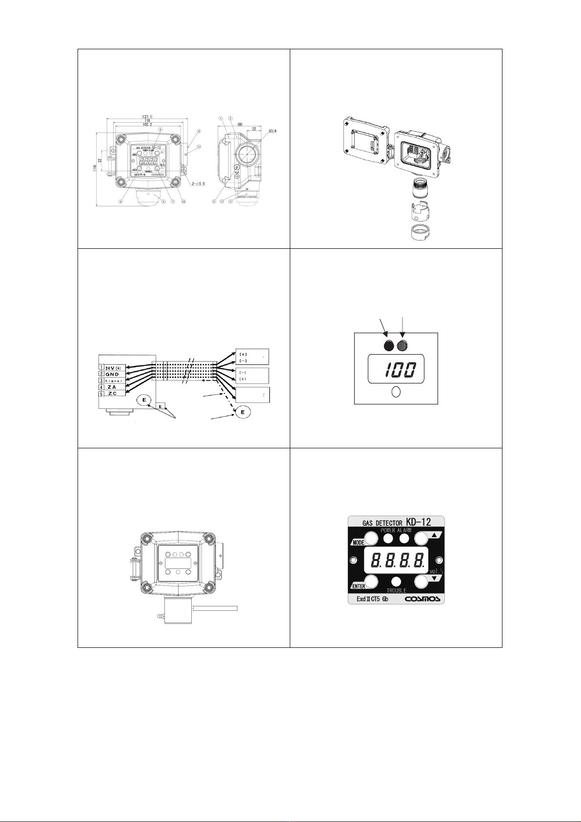
4. External Dimensions and Nomenclature
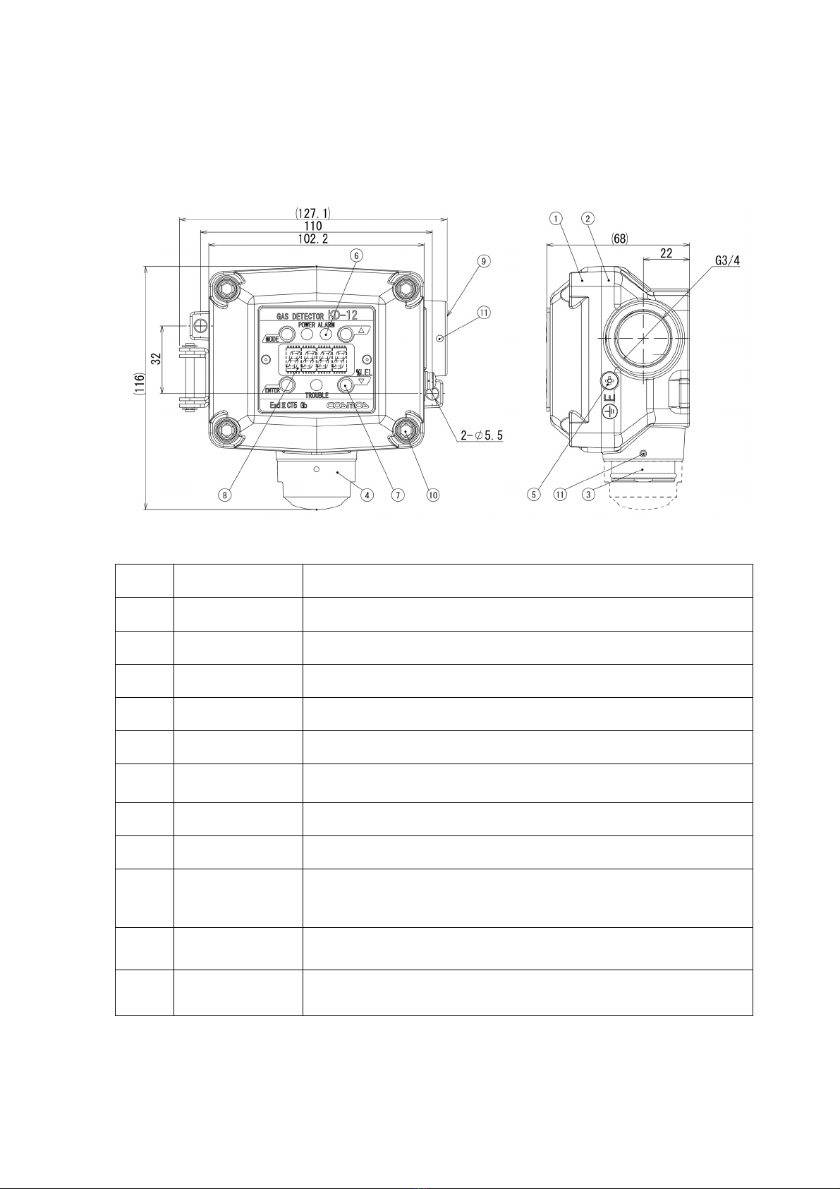
4-1. Main Unit
Number Name Description
1 Casing cover
2 Casing
3 Sensor unit Incorporates a gas sensor.
4 Sensor guard Protects the sensor unit.
5 Ground terminal Used when grounding the frame.
6 State display
indicator
Indicates the power supply state (green), alarm state (red), and trouble
state (yellow).
7 Control block Insert the magnetic stick to control or set the product.
8 Display block Displays the gas concentration and set values.
9
Cable entry
PF3/4orG3/4, pitch=1.81mm, Insertion length: 10.86mm,
No. of insertion threads: 6. Certified cable glands*1 must be
provided by end user and used.
10 Hexagon socket
head cap screw
Used for securing the casing cover. Use a hexagon wrench with a
nominal diameter of 4 mm.
11 Hexagon socket
set screw
Used for securing the cable glands or sensor units. Use a hexagon
wrench with a nominal diameter of 2 mm.
*1: Used in ATEX hazardous, ATEX certified cable glands according to EN60079-0:2012 and
EN60079-1:2007.Used in IECEx hazardous area, IECEx certified cable glands according to
IEC60079-0:2011 and IEC60079-1:2007.
5
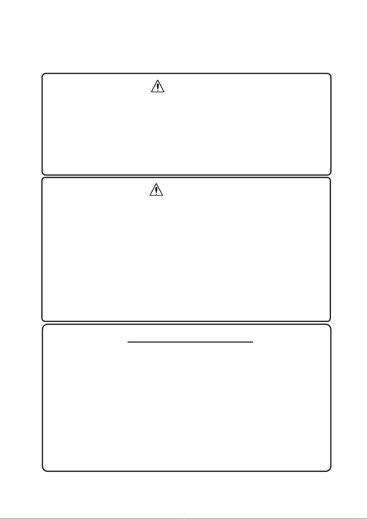
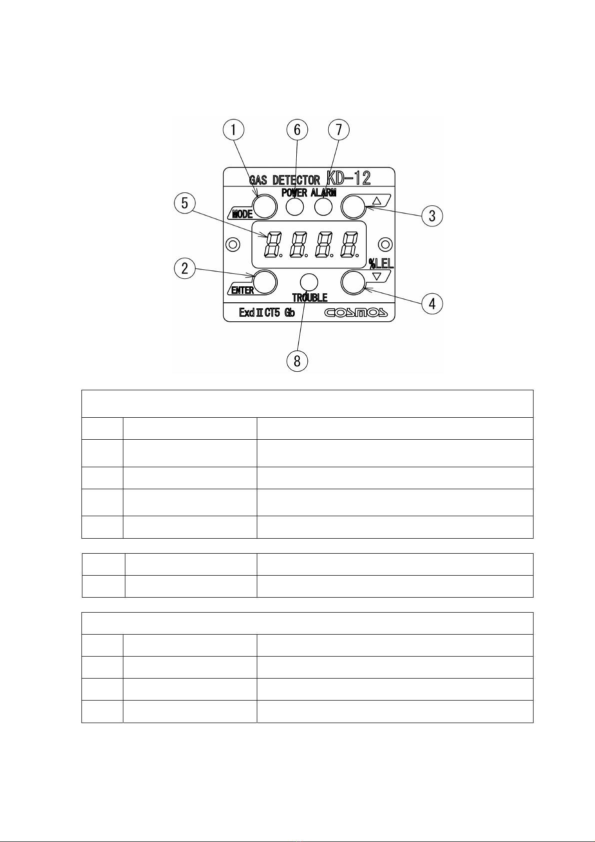
4-2. Display and Control Blocks
Magnetic switches
(Insert the magnetic stick to operate the magnetic switches.)
Number Name Description
1 MODE switch Makes adjustments and settings or cancels the operation of
the product.
2 ENTER switch Enters settings or completes the control of the product.
3 UP switch Makes adjustments and settings or increases set values and
other values.
4 DOWN switch Decreases set values and other values.
Number Name Description
5 Display block Displays the concentration of gas and set values.
State display indicator
Number Name Description
6 POWER indicator A green lamp to display the power supply state.
7 ALARM indicator A red lamp to display the alarm state.
8 TROUBLE indicator A yellow lamp to display the trouble state.
6
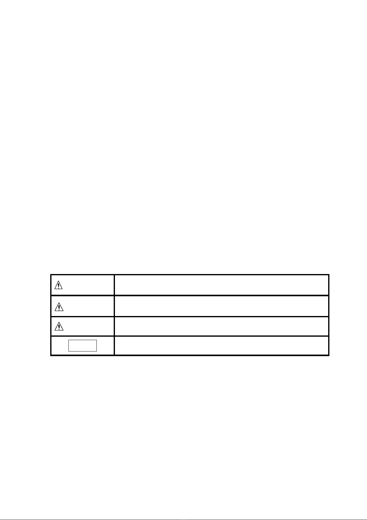
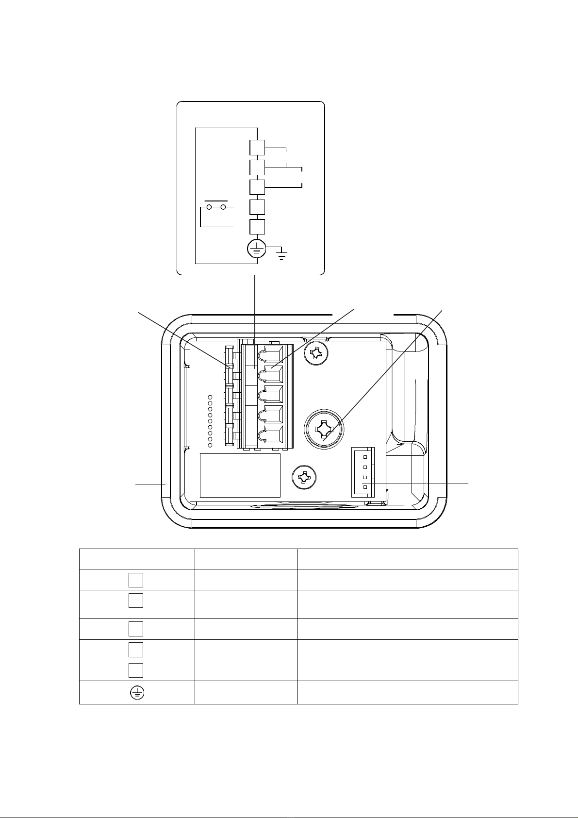
4-3. Terminal Block
Signal
ZA
ZC
24V(+)
GND
1
2
3
5
4
4~20mA
POWER
+
-
E
2
1
3
4
5
Number Name Description
1 24 V (+) Power supply voltage (positive)
2 GND Power supply voltage(-) and analog signal
(negative) common
3 Signal 4- to 20-mA(+) analog signal
4 ZA
External contact
5 ZC
Ground terminal Used to ground the frame.
Terminal block
Ground
terminal
Lever
Sensor
connector
O-ring
Clamp
4 to 20 mA
24 V (+)

7
5. Installation
5-1. Installation Method
WARNING
The cable entry device and blanking elements shall be of ATEX certified in type of
explosion protection flameproof enclosure ‘’d’’, suitable for the condition of use and
correctly installed.
Use in ATEX hazardous area, ATEX certified cable glands according to EN
60079-0:2012 and EN 60079-1:2007 shall be provided by end-user.
Use in IECEx hazardous area, IECEx certified cable glands according to IEC
60079-0:2011 and IEC60079-1:2007 shall be provided by end-user.
Unused apertures shall be closed with suitable ATEX certified blanking elements.
Fastener type M5 x 16 shall have a yield stress factor of min. 450 N/mm2.
The dimensions of flameproof joint between casing and casing cover of KD-12
flameproof housing are exceeding the minimum requirements stated
EN/IEC60079-1. Please contact the manufacturer for inspection, repair and/or
adjustments of this flameproof.
Installation of cable gland and sensor:
-Casing to cable glands -Casing to sensor
Thread size : PF3/4 or G3/4 Thread size : M27
Pitch : 1.81mm Pitch : 1.5mm
Insertion length : 10.86mm Insertion length : 8.25mm
Number of insertion threads : 6 Number of insertion : 5.5
Shall lock the sensor unit and cable gland by the stainless steel socket head screw
before use.
* Top of socket head screw shall not be over the casing surface.
8
Installing Height
Type of gas Installing height Remarks
Gas heavier than air
(Example: LPG)
A maximum of 10 cm above the
floor.
(Height to the sensor guard tip)
Keep a space of approximately
7 cm from the sensor guard tip
for ease of maintenance and
inspection.
Gas almost the same as
air in specific gravity
(Example: Carbon
monoxide)
75 to 150 cm above the floor.
(Height to the sensor guard tip)
Decide the height by considering
the specific gravity and mounting
environment.
Gas lighter than air
(Example: City gas and
hydrogen)
Near the ceiling
Decide the height by considering
arrangements for ease of
maintenance (e.g., a scaffold).
CAUTION
Be careful not to damage the gas detector when installing it. Otherwise, the
explosion-proof performance of the gas detector will be lost.
Do not install the product in the following places.
- Places where the ambient temperature exceeds the operating temperature
range (10C to 50C).
- Places where condensation occurs.
- Places where water is directly sprayed.
- Places subject to corrosive gas.
- Places close to equipment that generates high frequencies or a magnetic field.
- Places where silicone sealant is used or likely to be used.
- Places where silicone gas is used or likely to be used.
Install the gas detector in places where it can be maintained and inspected with
ease.
Install the gas detector in places free from vibration.
Install the gas detector in places free from sudden temperature changes.
Keep the gas detector free from impacts.
When installing the gas detector outdoors, be sure to install the protective cover
(optional).
The installing height of the gas detector has an important relation to the specific
gravity of the target gas to be detected. Install the gas detector in accordance
with required regulations.
Install the gas detector in the environment where there is no power outrage
including short interruption

9
Mount the main unit to the wall with the M5 screws that are provided with the product. Be sure
to install the protective cover (optional) when mounting the main unit outdoors. Mount the main
unit with a 2B pole mounting bracket (optional) when mounting the main unit to a 2B pole.
Refer to 5-3 Mounting of Options for details of optional products.
The casing cover of the gas detector needs be opened at the time of wiring. Therefore,
when installing the gas detector, provide sufficient space to enable the casing cover to be
opened to at least 90°.
Mounting hole
Mounting hole
90°or more

10
It is necessary to operate the detector during inspection or maintenance work. Therefore,
leave a distance of 50cm or more between the front side of the detector and the object in front
of it when installing it.
・
When installing this diffusion type gas detector on the ceiling or a higher location, make sure to
leave enough space just below the detector to allow for inspection or maintenance activities.
When installing the detector at a height more than 3m from the floor, we recommend you to
use a suction type gas detector with a sampling tube up to the ceiling.
A sensor guard is not necessary when installing the detector on the ceiling or a higher location.
However, when installing the detector on a lower place like the floor, a sensor guard is required
in order to protect the sensor from water splash.
Consider the direction of the gas flow and the hole of the sensor guard when installing.
Leave a distance of min. 50cm.
Gas flow
Install the sensor guard so that
the gas flows through the hole.
Leave space below the gas
detector for inspection or
maintenance purposes.

11
5-2. Examples of Installation Positions
Install the product in places where gas easily accumulates.
Example of Installation Position
Partition
wall Pipe
Valve
Detector
Flange
Example of Outdoor Installation Position
Entrance
(Suction port)
Roof fan
(Exhaust port)
Entrances and windows
(Suction and exhaust ports)
Gas detector
mounting
position
Places where gas easily accumulates.
Gas detector
Side view Plan view
12
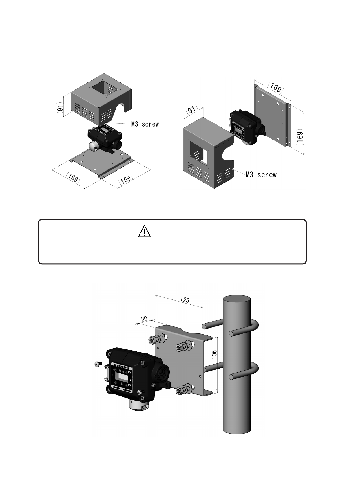
5-3. Mounting of Optional items
Protective Cover
Horizontal Type (KW-41) Vertical Type (KW-42)
2B Pole Mounting Bracket
CAUTION
Secure the casing cover with M3 screws if strong winds are expected.
13
6. Wiring Method
6-1. Wiring Work
Be sure to provide explosion-proof wiring if the product is to be used in hazardous places.
Cable Work
Use a shielded cable, such as CVV-S with a thickness of 1.25 to 2.00 mm2. Lay all cables in
protective tubes, such as metal conduits or carbon steel pipes, or other protective structure,
such as a concrete duct.
When using the external contact function of the product, which requires a five-conductor cable,
make sure that the maximum diameter of the cable conductor is 1.25 mm2. When using only
the analog signal function, which requires a three-conductor cable, without the external
contact function, make sure that the maximum diameter of the cable conductor is 2.00 mm2.
CAUTION
All necessary work for the product including wiring and installation should be carried out
by suitably trained personnel in accordance with applicable code of practice.
Inspection, maintenance and repair of the equipment should be carried out by suitably
trained personnel in accordance with applicable code of practice.
WARNING
The cable entry device and blanking elements shall be of ATEX certified in type of
explosion protection flameproof enclosure ‘’d’’, suitable for the condition of use and
correctly installed.
Unused apertures shall be closed with suitable ATEX certified blanking elements.

14
CAUTION
Wire the connecting terminals correctly.
Separate connection cables from power lines as far as possible.
When closing the casing cover, make sure that the power supply cord, harness, and
O-ring are not caught by the casing cover.
6-2. Wiring and Connection
Connecting Power Supply and Signal Wires
Provide dedicated breakers, if needed, to lines that are connected to peripheral devices, such
as indicator units and signal converters.
Use a dedicated cable, such as CVV-S (with a thickness of 1.25 to 2.00 mm2).
Make sure that the power supplied to the product is within the specified voltage range.
Make sure that the load resistance of the signal line, including the resistance of the wire, is 300
ohm or less.
WARNING
Before opening the casing cover of the gas detector, be sure to turn off the product and
all devices (e.g., indicator unit and signal converter) connected to the product.
If the power is turned ON, the power supply may become a source of ignition.
Be sure to ground the product to prevent electric shocks.
Shall use a conductor which is at least M4 size by solderless, for external earthing.
Shall place the stainless steel plain washer between casing and terminal.
15
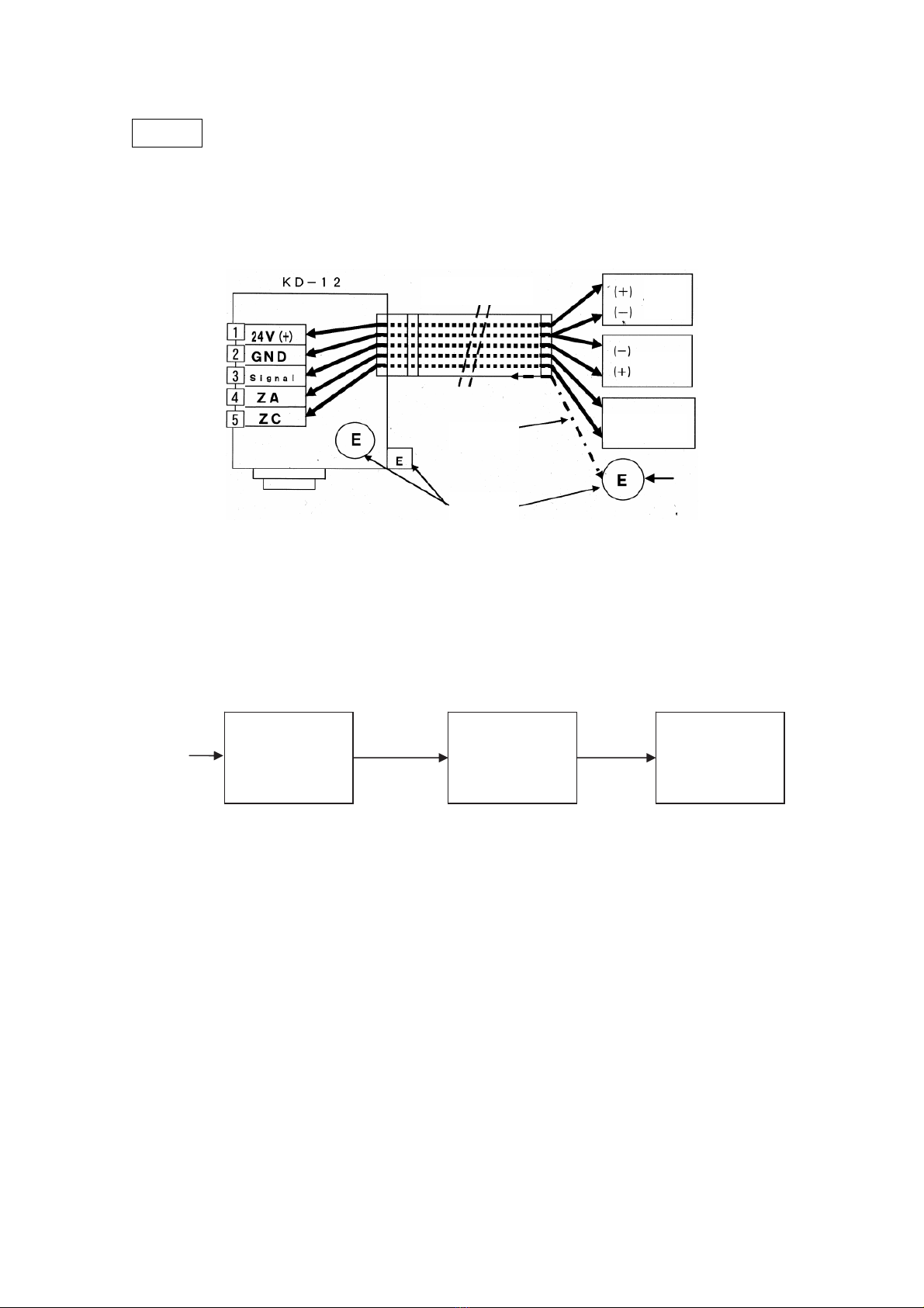
MEMO
If the main unit is grounded on the power supply side, do not connect a shielded cable to the
ground terminal (E) in the gas detector, or otherwise two-point grounding will result.
Connection Example with Power Supply Side Grounded
System Configuration Example
For details, refer to the Instruction Manual of each device.
KD-12B
SIL
PLC
Valves
4-20 mA
Gas
Controller
Sensor Subsystem Logic Subsystem Actuator Subsystem
指示計
ユニット
電源
2
G
roun
d
terminals
CVVS cable 24V
power
supply
Indicator
S
hield External alarm
Ground terminal on
power supply side
Not grounded Grounded

16
Typical Connection Procedure
(1) Prepare a power supply that can provide 24 V.
(Do not turn on the power supply before wiring the main unit.)
(2) Loosen the hexagon socket bolts on the four corners of the main unit using the provided
hexagon wrench with a nominal diameter of 4 mm, and open the casing cover of the main
unit.
(3) Press the lever of the terminal block with a flat-blade screwdriver.
(4) The clamp will open. Insert the lead wire.
(5) Connect the positive side of the power supply to the 24 V+ terminal.
(6) Connect the negative side of the power supply to the GND terminal.
(7) The lead wire will be automatically secured when the screwdriver is lifted.
(8) Check that the power supply cords are securely connected to the terminals. This
completes the power supply preparations.
(9) Wire the analog signal and external contact terminals, if required.
(10) Tighten the hexagon socket bolts (tightening torque : 0.8 – 2.4 N・m) on the four corners of
the main unit and close the casing cover of the main unit.
CAUTION
When lowering the lever of the terminal block, be careful not to allow the flat-blade
screwdriver to slip off of the lever. Otherwise, the flat-blade screwdriver may damage the
harness or circuit board.
When closing the casing cover, make sure that the power supply cord, harness, and
O-ring are not caught by the casing cover.

17
7. Precautions before Use
In Case of Gas Leakage
WARNING
If there is a gas leak alarm, take the necessary measures specified by your company.
If a gas leak occurs indoors, open the windows and doors to ventilate the room.
Check the gas leakage location and promptly take the necessary measures.
Measure the gas concentration with a portable gas detector and confirm the safety
before entering the detection site.
DANGER
Without panicking, check that there is no fire around the product. Do not touch any
electric switches under any conditions. Sparks from turning electric switches ON or OFF
may cause ignition.
CAUTION
Before turning ON any of the devices (e.g., indicator unit, signal converter) connected to
the product, recheck that all of the connections are correct. Make sure that the gas
detector and indicator unit or signal converter, in particular, are connected properly.
Table of contents
Other New Cosmos Electric Gas Detector manuals

New Cosmos Electric
New Cosmos Electric XPS-7II User manual

New Cosmos Electric
New Cosmos Electric XA-4400II User manual

New Cosmos Electric
New Cosmos Electric PE-2CC User manual

New Cosmos Electric
New Cosmos Electric ML-310 User manual

New Cosmos Electric
New Cosmos Electric KD-12 User manual

New Cosmos Electric
New Cosmos Electric PS-7 User manual

New Cosmos Electric
New Cosmos Electric KD-12 User manual

New Cosmos Electric
New Cosmos Electric KS-7D User manual

New Cosmos Electric
New Cosmos Electric PS-7-M Use and care manual

New Cosmos Electric
New Cosmos Electric XP-3000II Series User manual


