manuals.online logo
Brands
  1. Home
  2. •
  3. Brands
  4. •
  5. ATO
  6. •
  7. Gas Detector
  8. •
  9. ATO YT-95H-XX User manual

ATO YT-95H-XX User manual

Matters need attention
A. Please read this instruction manual before using the detector.
B. The detector must be used in compliance with the designated procedures of our company.
C. The warranty period of this transmitter is 12months (starts from the date userget the detector).
Users should comply with the instructionsin the use of this detector. Any damages or malfunctions
caused by improperoperation of users are not within the scope of warranty.
D. Repairand replacement of any parts must be operated by trained staff under authorization of
our company, using original spare part. The operatoris responsible for the liability if users operate
the repair of replacement by themselves.
E. There is acid solution inside the transmitter, please do not disassembleit. And pay attention not
to damage the frontal membrane of the transmitter. If the skin is stained with the acid solution. the
right remedy is to flushing the stained skin continuously with clean water for 1 0minutes.
F. The detector must be calibrated for once each year. The explosion proof sheet parts of the
transmitter need to be cleaned regularly (blow with low pressure compressedair), otherwise the
detection sensitivity will be affected by the dust and impurities clogging protection hole.
3
2
1.Power supply, signal line
2.Printed-circuit board
3.Terminal
4.Sound and tight alarm port
5.Air chamber of sensor
6.Sensor port
7.Main board connection
Ground
connectio n port
5
6
123
4
7
1. Key Technical Indicator
Repeatability: <2%
Zero drift: < ± 2% (F•S) /6M
Operating temperature: -20~+50℃
Environment temperature: <90%RH
Working principle of the transmitter: electrochemical for oxygen and hazardous gases, catalytic
combustion for combustible gases
Lifespan of transmitter: 3years for combustible gas transmitter; 2years for hazardous gas
transmitter
2. Other Technical Parameters
Inspection mode: diffusion
Working mode: fixed long-term continuous work
Working voltage: 12-30V DC
Working current: oxygen and hazardous gas <50mA (Max)
combustible gas <150mA (Max)
Technical performance and parameters
Notice to Reader
Please read this instruction manual before using the detector
Output signal: three-wire 4-20 mA standard signal output or RS485 signal output
Exterior structure: die-casting aluminum housing
Dimensions: 135 x 125 x 116mm (without mounting bracket)
167 x 145 x 126mm (with bracket)
Weight: without mounting brackets 1.2kg with brackets 1.6kg with stent
Connection cable (6 core cable) is defined as follows:
4-20mA with RS485:
Red: positive-input of power (12 to 24V)/ 24V+
Black: ground wire of power/24V
Yellow:4-20mA output.
Orange: RS485A
Blue: RS485B
Brown: Free
Connection distance: >1000m
Protection grade: IP65
Installation type: on wall
Type of explosion-proof: flame proof
Explosion-proof grade: Ex d IIC T6 Gb
Inlet port: hexagonal locknut
Settings of Remote Control
The remote control applied to all product type produced by Yuante.
1. Press "MENU" once to enter F01, address code setting menu. Press "OK" to modify, press"+""-
"to modify address code of the detector. Press "OK" to save settings and "BACK" to cancel.
2. Press "MENU", then press “+”to enter F02, minimum value setting menu of gas alarm, Press
"OK" to modify, press"+" "-"to modify the value. Press "OK" to save settings and "BACK" to
cancel.
3. Continue to press "+"to enter F03, maximum value setting menu of gas alarm., Press "OK" to
modify, press"+" "-"to modify the value. Press "OK" to save settings and "BACK" to cancel. Same
operation with F04 (zero point calibration), F05 (range calibration), F06 (AD value).
4. Press "MENU" four times to enter a shift status, under this status:
Press "RESET" once, the data would be 255, one more it would be 0. Just press "RESET" to shift.
When the data is 0, press "+"or"-"to modify alarm point, the data difference would be only 1. When
the data is 255, press "+"or"-"to modify alarm point, the data difference would be 1000. "RESET"
can also be used as mute button when it is alarming.
1
4
Fixed Gas Detector
YT-95H-:XX
Instruction Manual
Target gas
Range
Accuracy
least count
response time
O2
0-30%VOL
<±2%(F.S)
0.01%VOL
≤15
H2S
0-1000ppm
<±2%(F.S)
1ppm
≤15
CO
0-1000ppm
<±2%(F.S)
1ppm
≤25
H2
0-20000ppm
<±2%(F.S)
1ppm
≤15
CO2
0-10000ppm
<±2%(F.S)
1ppm
≤40
C2H4
0-100ppm
<±2%(F.S)
0.01ppm
≤60
NO2
0-20.0ppm
<±2%(F.S)
0.1ppm
≤25
N2
0-100%VOL
<±2%(F.S)
0.01%VOL
≤40
TVOC
0-6000ppm
<±2%(F.S)
1ppm
≤60
NH3
0-100ppm
<±2%(F.S)
0.01ppm
≤40
ASH3
0-10.00ppm
<±2%(F.S)
0.01ppm
≤30
C3H3N
0-200.0ppm
<±2%(F.S)
0.1ppm
≤40
F2
0-10 ppm
<±2%(F.S)
0.01ppm
≤25
O3
0-5.00ppm
<±2%(F.S)
0.01ppm
≤50
CL2
0-10.00ppm
<±2%(F.S)
0.01ppm
≤60
BF3
0-10.00ppm
<±2%(F.S)
0.01ppm
≤60
NC:Normally close
NO:Normally open
COM:Common
24V:24+,positive
GND:24-,negative
4~20mA:4~20mA analog signal
High Alarm
Low Alarm
RelayRelay
Powered
Signal output
Motherboard connector Alarm
Digital probe portDigital probe portDigital probe port
Port Instruction
www.ato.com [email protected] 18005851519 Global Shipping www.ato.com [email protected] 18005851519 Global Shipping
Function introduction
Controller function introduction
F-01 Address, Range1-200
F-02 Low point alarm
F-03 High point alarm
F-04 Zero calibration
F-05 4mA offset correction
F-06 ADC check
F-07 Standard gas concentration
F-08 Calibration switch
F-09 Production date
F-10 Reserved function
F-11 Serial communication check. 0 no check, 1 odd check, 2 even check
F-12 Arrangement mode of the floating-point data
0:DCBA
1:ABCD
2:CDAB
Need to press OK to save after all the above parameters are modified, which can take effect
immediately, power outage restart also valid.
MENU
RESET
OK
+
BACK
-
MENU button, from the measurement state into the functional state
alarm reset to eliminate alarm function
confirm button
plus
return
minus
Remote controller function
Installation Instruction
1. Location Selection
The location selection of the gas detection transmitter is essential to achieve the best detection
results. In the selection of location, we need to consider the following factors: the density of gas in a
leaking point, proportion of target gas, the impact of surrounding buildings, condition of production
equipment, wind direction and annual meteorological conditions and even the location of windows
and doors in an indoor environment.
We provide the following suggestions for your reference:
A. Maintain a proper distance between the detector and the possible gas leaking point. It would
react too fast or too frequent if the distance is not enough, which may paralyze people's mind.
B. The detector must be located in the downwind of the possible leaking point.
C. If installed indoor, but the source of the leak is outdoor, the detector must be installed at the air
inlet.
D. Determine the height according to proportion of target gas in air.
E. Determine the quantity of detectors according to the condition of possible leaking point,
frequency of staff attendance and time of stay as well as the economic effect.
F. Consider to increase quantity of inspection point if the equipment is old.
G. Protect the detector from radiation of high temperature heart source. Environments of both
very high temperature and very low temperature will affect the result and lifespan of the detector.
118.00
φ8.00
140.00
φ8.00 φ8.00
102.30
206.00
89.00
Method of Calibration
To guarantee the measurement accuracy of the transmitter, regular calibration and maintaining
rigorous record is necessary.
Devices needed for calibration: a bottle of sample gas used for range calibration (60%F.S standard
gas in normal site),relief valve, flow meter of 0~1000ml/min, transparent and smooth conduit for
gas, standard gas housing, digital multimeter, stopwatch and etc.
Note: The value of transmitter WB (4mA) , WC (20mA) , Wz (zero potentiometer), WA (range
potentiometer, also known as calibration potentiometer) and host alarm has been set right before it
leaves the factory. User should not adjust casually. It is the value of zero potentiometer (Z) and
calibration potentiometer (S) needed to be set on spot.
1. Zero Point Calibration
Open the detector in clean air, if there is readings after counting down.
Press the button "MENU" of the remote controller, the detector displays "F-01", press"+" or"-",
change the function to "F-04", and click "OK". The detector value will be displayed as 0.
In the zero calibration of oxygen detection transmitter, we must use nitrogen of purity over
99.99%.
Common Malfunction, Repair and Maintenance
Product component
Fixed Gas Detector
Instruction Manual
Qualification Certificate
Remote Control
one
one
one
one
7
6
5
8
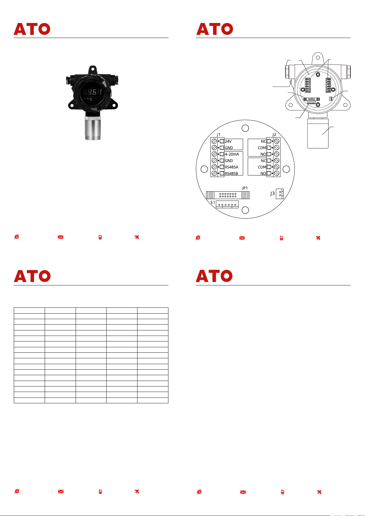
2. Steps of Installation
Connect wire to correspondent terminals. Don't work with power on. The arrangement of
terminals differs according to the type of transmitter. The definition of different wires:
Red: positive-input of power (12 to 24V)/24V+
Black: ground wire of power/24V
Yellow:4-20mA output.
Orange: RS485A
Blue: RS485B
Brown: Free
Fix the detector on the wall with expansion bolt, make sure the transmitter is downward, or the
detector cannot work property. Users can also separate the bracket and transmitter according to the
condition on spot, fix the bracket before connection.
For the sake of safety and interference reduction, please connect the housing with reliable ground
wire. For the wire between the transmitter and the main engine, the shorter, the better. And protect
the wire with iron pipe.
Symptom
Reason
Method to process
No output
for
transmitter
wrong connection
connect again
potential in reference point is
not correct
Adjust zero point gradually and then adjust potentiometer (4mA)
Circuit fault
Return to Yuante for repair
Too low
host
reading
Value of S potentiometer
setting is too small
Calibrate again
Transmitter failure
Get a new transmitter
Too high
host
reading
Value of S potentiometer
setting is too large
Calibrate again
Transmitter failure
Get a new transmitter
Instable
host
reading
Heat settling time is not
enough
Wait for starting up
Transmitter failure
Get a new transmitter
Circuit fault
Return to Yuante for repair
PRV
PTFE PIPE
Empty
Gas detector
Standard gas
Flowmeter
2. Range Calibration
1. Enter into "F-07"as the same way above . The
"F-07" value is the concentration of the standard
gas, initialized to half of the measure range. This
value can be modified through the"+" and"-" keys to
make it consistent with the standard gas
concentration which need to be calibrated. Press
"OK" to exit.
2. Enter into"F-08"to change 0 into 1,then back to
detection interface.
3. Connect the 200-400mL/min standard gas in
detection interface, when the detector value is
stable, press "OK" for 3 seconds, then the
instrument will be calibrated automatically. The
measured concentration value is consistent with the
value set in "F-07".
4. After calibration, left the detector in the air for a
while. Shut off the power when the detector value is
close to zero.
www.ato.com [email protected] 18005851519 Global Shipping www.ato.com [email protected] 18005851519 Global Shipping

Other ATO Gas Detector manuals

ATO ATO-GAS-S4 User manual

ATO

ATO ATO-GAS-S4 User manual

ATO YT-1200H-S4 User manual

ATO

ATO YT-1200H-S4 User manual

Popular Gas Detector manuals by other brands

Honeywell Gamewell-FCI E3 Series quick start guide

Honeywell

Honeywell Gamewell-FCI E3 Series quick start guide

PNI SafeHouse HS110 user manual

PNI

PNI SafeHouse HS110 user manual

BEINAT RGX100 quick start guide

BEINAT

BEINAT RGX100 quick start guide

Refco STARTEK-C operating manual

Refco

Refco STARTEK-C operating manual

Kidde KN-COP-DP-10YL-AQ-WF-CA user guide

Kidde

Kidde KN-COP-DP-10YL-AQ-WF-CA user guide

olympia electronics BS-690 quick start guide

olympia electronics

olympia electronics BS-690 quick start guide

Safety first Scentry III-GFRAB Installation and operating instructions

Safety first

Safety first Scentry III-GFRAB Installation and operating instructions

Aereco S-C02/T Installation and maintenance  instruction

Aereco

Aereco S-C02/T Installation and maintenance instruction

Dräger X-am 7000 Instructions for use

Dräger

Dräger X-am 7000 Instructions for use

Riken Keiki FI-915 operating manual

Riken Keiki

Riken Keiki FI-915 operating manual

GasDog GD300 Series instruction manual

GasDog

GasDog GD300 Series instruction manual

TPI 770 instruction manual

TPI

TPI 770 instruction manual

Blackline Safety G6 Technical  user's manual

Blackline Safety

Blackline Safety G6 Technical user's manual

Tecnocontrol SE138K user manual

Tecnocontrol

Tecnocontrol SE138K user manual

Tecnocontrol Beta Series quick start guide

Tecnocontrol

Tecnocontrol Beta Series quick start guide

Tecnocontrol TS293PE user manual

Tecnocontrol

Tecnocontrol TS293PE user manual

Tecnocontrol SE155M user manual

Tecnocontrol

Tecnocontrol SE155M user manual

Evikon E2611-LEL user manual

Evikon

Evikon E2611-LEL user manual

manuals.online logo
manuals.online logoBrands
  • About & Mission
  • Contact us
  • Privacy Policy
  • Terms and Conditions

Copyright 2025 Manuals.Online. All Rights Reserved.