Metrohm 772 User manual

772 Pump Unit
Manual
8.772.8001EN / 2019-11-29


Metrohm AG
CH-9100 Herisau
Switzerland
Phone +41 71 353 85 85
Fax +41 71 353 89 01
www.metrohm.com
772 Pump Unit
Manual
8.772.8001EN / 2019-11-29

Technical Communication
Metrohm AG
CH-9100 Herisau
This documentation is protected by copyright. All rights reserved.
This documentation has been prepared with great care. However, errors
can never be entirely ruled out. Please send comments regarding possible
errors to the address above.

■■■■■■■■■■■■■■■■■■■■■■ Table of contents
772 Pump Unit ■■■■■■■■ III
Table of contents
1 Introduction 1
1.1 Instrument description ......................................................... 1
1.1.1 Model versions ........................................................................ 1
1.1.2 Connectors .............................................................................. 1
1.1.3 Intended use ........................................................................... 1
1.2 About the documentation ................................................... 2
1.2.1 Symbols and conventions ........................................................ 2
1.3 Safety instructions ................................................................ 3
1.3.1 General notes on safety ........................................................... 3
1.3.2 Electrical safety ........................................................................ 3
1.3.3 Tubing and capillary connections ............................................. 4
1.3.4 Flammable solvents and chemicals ........................................... 4
1.3.5 Recycling and disposal ............................................................. 4
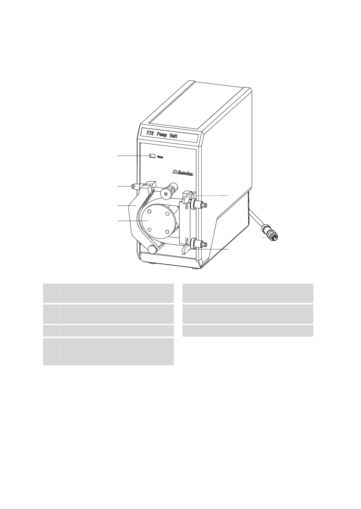
2 Overview of the instrument 6
3 Installation 7
3.1 Setting up the instrument .................................................... 7
3.1.1 Packaging ................................................................................ 7
3.1.2 Checks .................................................................................... 7
3.1.3 Location .................................................................................. 7
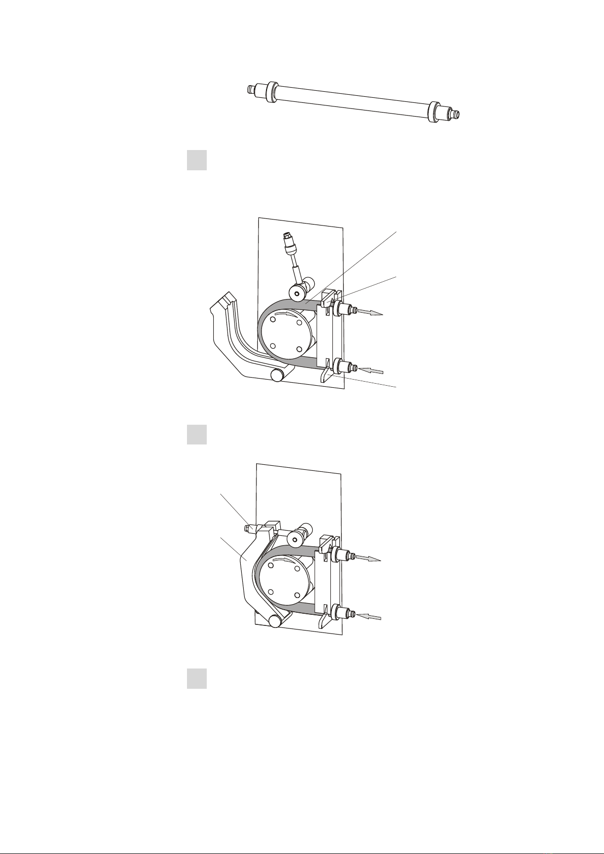
3.2 Mounting the tubings .......................................................... 7
3.2.1 Mounting the pump tubing ..................................................... 7
3.2.2 Installing the inlet tubing and outlet tubing .............................. 9
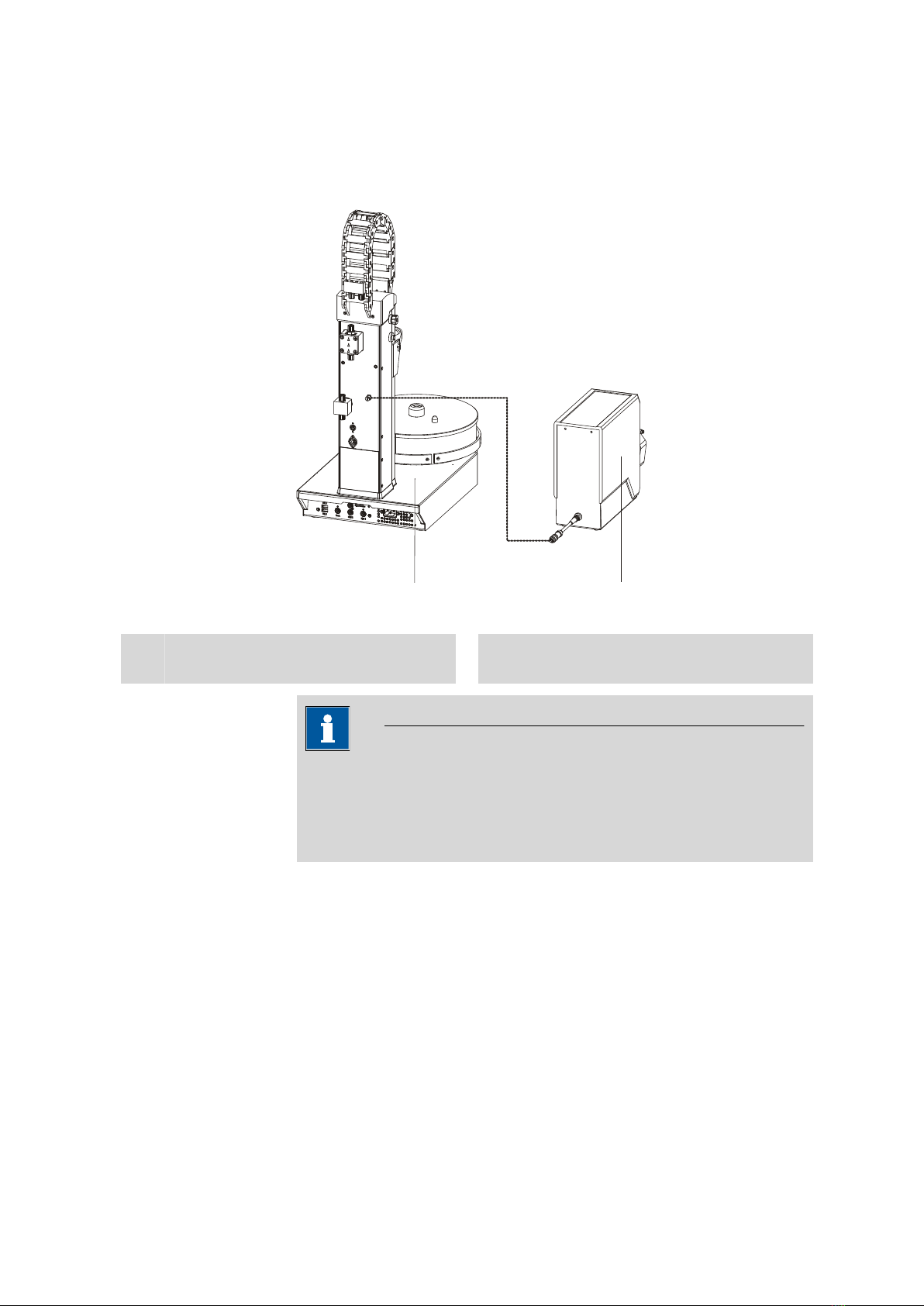
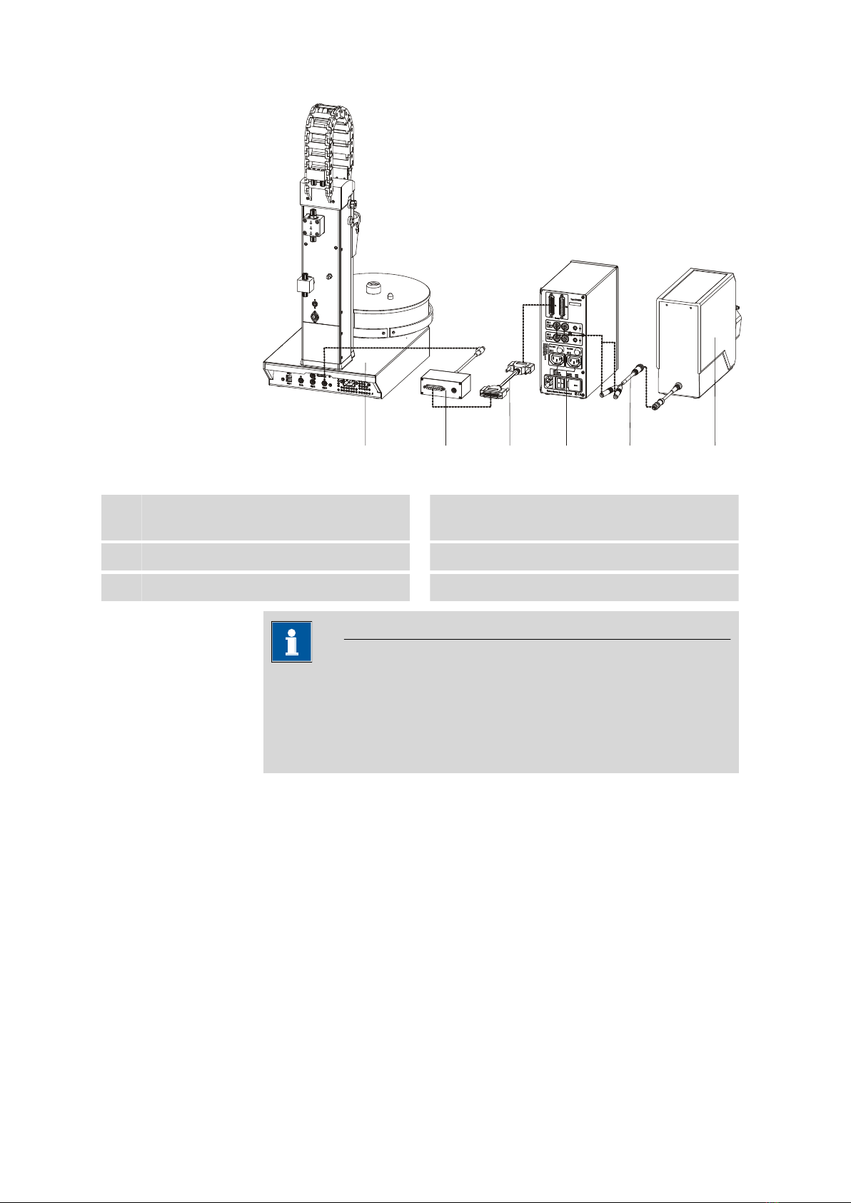
3.3 Connecting the peristaltic pump ....................................... 10
3.3.1 Connection to a Sample Processor ......................................... 11
3.3.2 Connection to the 731 Relay Box .......................................... 11
4 Operation 14
5 Operation and maintenance 15
5.1 General notes ...................................................................... 15
5.1.1 Care ...................................................................................... 15
5.1.2 Maintenance by Metrohm Service .......................................... 15
5.2 Pump tubings ...................................................................... 16
5.2.1 Selecting the pump tubing ..................................................... 16
5.2.2 Suitability test for tubing materials ......................................... 17
5.2.3 Tubing dimensions ................................................................. 17
5.2.4 Tubing lifetime ....................................................................... 17
5.2.5 PharMed® pump tubing data sheet ....................................... 18
5.2.6 Viton® pump tubing data sheet ............................................ 19
5.3 Tubings ................................................................................ 20

Table of contents ■■■■■■■■■■■■■■■■■■■■■■
IV ■■■■■■■■ 772 Pump Unit
6 Troubleshooting 21
6.1 Problems .............................................................................. 21
7 Technical specifications 22
7.1 Peristaltic pump .................................................................. 22
7.2 Power supply ...................................................................... 22
7.3 Interfaces and connectors ................................................. 22
7.4 Ambient temperature ......................................................... 22
7.5 Reference conditions .......................................................... 23
7.6 Dimensions/material ........................................................... 23
8 Accessories 24
Index 25

■■■■■■■■■■■■■■■■■■■■■■ Table of figures
772 Pump Unit ■■■■■■■■ V
Table of figures
Figure 1 Front 772 Pump Unit ......................................................................... 6
Figure 2 Inserting the tubing olives ................................................................. 7
Figure 3 Installing the pump tubing ................................................................ 8
Figure 4 Fastening the pressure clamp in place ................................................ 8
Figure 5 Connecting the tubings ..................................................................... 9
Figure 6 Screwing the union nuts tightly ....................................................... 10
Figure 7 772 Pump Unit directly on the Sample Processor ............................. 11
Figure 8 772 Pump Unit via the Remote Box and 731 Relay Box .................... 12
Figure 9 Direction of rotation ........................................................................ 13
Figure 10 Calculation formula for the permeability (C) ..................................... 19


■■■■■■■■■■■■■■■■■■■■■■ 1 Introduction
772 Pump Unit ■■■■■■■■ 1
1 Introduction
1.1 Instrument description
The 772 Pump Unit is a versatile peristaltic pump for conveying or evacu-
ating liquid media. It was designed specifically for the production opera-
tion and laboratory environment and enables a wide range of applica-
tions. Unlike membrane pumps, pumping organic solvents or liquids with
solids content is no problem for the 772 Pump Unit.
Therefore, the 772 Pump Unit is equally well suited for use in titration, e.g.
for evacuating titration samples with silver halide precipitation and as a
delivery pump in larger automation systems. By using the respective suit-
able tubing material, a wide variety of tasks can be managed.
The flow rate of up to 600 mL/min opens up a wide range of applications.
1.1.1 Model versions
The 772 Pump Unit is available in the following three versions:
2.772.0110 772 Pump Unit
2.772.0120 772 Pump Unit with aspiration equip-
ment
2.772.0130 772 Pump Unit with rinsing equipment
Each version includes different accessories according to its use (see chap-
ter 8, page 24).
1.1.2 Connectors
The 772 Pump Unit needs 16 - 24 V DC voltage.
Power is supplied to the pump via the direct connection to a Sample Pro-
cessor (e.g. 814 or 815) or to the 731 Relay Box (connection via adapter
cable 6.2160.010).
1.1.3 Intended use
The 772 Pump Unit is designed for usage in automated systems in analyti-
cal laboratories.
This instrument is suitable for pumping chemicals and flammable samples.
Use of the 772 Pump Unit therefore requires the user to have basic knowl-
edge and experience in handling toxic and caustic substances. Knowledge
with respect to the application of the fire prevention measures prescribed
for laboratories is also mandatory.

1.2 About the documentation ■■■■■■■■■■■■■■■■■■■■■■
2■■■■■■■■ 772 Pump Unit
1.2 About the documentation
CAUTION
Please read through this documentation carefully before putting the
instrument into operation. The documentation contains information
and warnings which the user must follow in order to ensure safe opera-
tion of the instrument.
1.2.1 Symbols and conventions
The following symbols and formatting may appear in this documentation:
Cross-reference to figure legend
The first number refers to the figure number, the sec-
ond to the instrument part in the figure.
Instruction step
Carry out these steps in the sequence shown.
Method Dialog text, parameter in the software
File ▶ New Menu or menu item
[Next] Button or key
WARNING
This symbol draws attention to a possible life-threat-
ening hazard or risk of injury.
WARNING
This symbol draws attention to a possible hazard due
to electrical current.
WARNING
This symbol draws attention to a possible hazard due
to heat or hot instrument parts.
WARNING
This symbol draws attention to a possible biological
hazard.
CAUTION
This symbol draws attention to possible damage to
instruments or instrument parts.

■■■■■■■■■■■■■■■■■■■■■■ 1 Introduction
772 Pump Unit ■■■■■■■■ 3
NOTE
This symbol highlights additional information and
tips.
1.3 Safety instructions
1.3.1 General notes on safety
WARNING
Operate this instrument only according to the information contained in
this documentation.
This instrument left the factory in a flawless state in terms of technical
safety. To maintain this state and ensure non-hazardous operation of the
instrument, the following instructions must be observed carefully.
1.3.2 Electrical safety
The electrical safety when working with the instrument is ensured as part
of the international standard IEC 61010.
WARNING
Only personnel qualified by Metrohm are authorized to carry out service
work on electronic components.
WARNING
Never open the housing of the instrument. The instrument could be
damaged by this. There is also a risk of serious injury if live components
are touched.
There are no parts inside the housing which can be serviced or replaced
by the user.
Supply voltage
WARNING
An incorrect supply voltage can damage the instrument.
Only operate this instrument with a supply voltage specified for it (see
rear panel of the instrument).

1.3 Safety instructions ■■■■■■■■■■■■■■■■■■■■■■
4■■■■■■■■ 772 Pump Unit
Protection against electrostatic charges
WARNING
Electronic components are sensitive to electrostatic charges and can be
destroyed by discharges.
Do not fail to pull the power cord out of the power socket before you
set up or disconnect electrical plug connections at the rear of the
instrument.
1.3.3 Tubing and capillary connections
CAUTION
Leaks in tubing and capillary connections are a safety risk. Tighten all
connections well by hand. Avoid applying excessive force to tubing con-
nections. Damaged tubing ends lead to leakage. Appropriate tools can
be used to loosen connections.
Check the connections regularly for leakage. If the instrument is used
mainly in unattended operation, then weekly inspections are manda-
tory.
1.3.4 Flammable solvents and chemicals
WARNING
All relevant safety measures are to be observed when working with
flammable solvents and chemicals.
■Set up the instrument in a well-ventilated location (e.g. fume cup-
board).
■Keep all sources of flame far from the workplace.
■Clean up spilled liquids and solids immediately.
■Follow the safety instructions of the chemical manufacturer.
1.3.5 Recycling and disposal
This product is covered by European Directive 2012/19/EU, WEEE – Waste
Electrical and Electronic Equipment.
The correct disposal of your old instrument will help to prevent negative
effects on the environment and public health.

■■■■■■■■■■■■■■■■■■■■■■ 1 Introduction
772 Pump Unit ■■■■■■■■ 5
More details about the disposal of your old instrument can be obtained
from your local authorities, from waste disposal companies or from your
local dealer.

■■■■■■■■■■■■■■■■■■■■■■
6■■■■■■■■ 772 Pump Unit
2 Overview of the instrument
1
2
3
4
5
6
7
Figure 1 Front 772 Pump Unit
1Status LED
For displaying the operating state.
2Locking lever with clamping screw
3Pressure clamp
For the counterpressure to the pump tubing.
4Rotor
5Tubing clamp (outlet) 6Tubing clamp (inlet)
7Connection cable
With M8 plug for connection to a Sample
Processor.

■■■■■■■■■■■■■■■■■■■■■■ 3 Installation
772 Pump Unit ■■■■■■■■ 7
3 Installation
3.1 Setting up the instrument
3.1.1 Packaging
The instrument is supplied in protective packaging together with the sepa-
rately packed accessories. Keep this packaging, as only this ensures safe
transportation of the instrument.
3.1.2 Checks
Immediately after receipt, check whether the shipment has arrived com-
plete and without damage by comparing it with the delivery note.
3.1.3 Location
The instrument has been developed for operation indoors and may not be
used in explosive environments.
Place the instrument in a location of the laboratory which is suitable for
operation and free of vibrations and which provides protection against
corrosive atmosphere and contamination by chemicals.
The instrument should be protected against excessive temperature fluctua-
tions and direct sunlight.
3.2 Mounting the tubings
3.2.1 Mounting the pump tubing
NOTICE
Selecting the correct pump tubing is very important for its function and
lifetime (see chapter 5, page 15).
1Cut the pump tubing to a length of approx. 17 cm.
2Insert the tubing olives (6.1820.050) into the two tubing ends.
Figure 2 Inserting the tubing olives

3.2 Mounting the tubings ■■■■■■■■■■■■■■■■■■■■■■
8■■■■■■■■ 772 Pump Unit
3Clamp the pump tubing 1 into the pump head according to the
drawing below such that the tubing and the tubing olives are fas-
tened by the tubing clips 2 and 3. The tubing must be as centered
on the roller as possible.
1
2
3
Figure 3 Installing the pump tubing
4Press on the pressure clamp 5 and fasten it in place using the locking
lever 4.
4
5
Figure 4 Fastening the pressure clamp in place
5Tighten the clamping screw 4 so that the pump tubing cannot slip.
With the pump running, gently tighten the clamping screw until the

■■■■■■■■■■■■■■■■■■■■■■ 3 Installation
772 Pump Unit ■■■■■■■■ 9
liquid flows evenly. After a run-in period, correct the setting again if
necessary.
NOTICE
Do not clamp the pump tubing too tightly or apply too much pres-
sure, as this causes greater wear to the pump tubing and the
pump will generate excessive pump pressure.
3.2.2 Installing the inlet tubing and outlet tubing
As the inlet tubing and outlet tubing, two different tubing types are avail-
able. Both tubings are included in the scope of delivery .
■PVC tubing (6.1801.120), 2 x 2 m
■PTFE tubing (6.1812.000), 1 x 4 m
NOTICE
Which of the two tubings to use depends largely on the solvent used.
PVC tubing is more flexible and has the advantage of making less noise
during the pumping operation. It must be noted that the PVC tubing is
not resistant to solvents.
Install the inlet tubing and outlet tubing as follows:
1Cut the inlet tubing and outlet tubing to the suitable length.
2Connect the tubings to the tubing olives of the pump tubing using
union nuts.
Figure 5 Connecting the tubings

3.3 Connecting the peristaltic pump ■■■■■■■■■■■■■■■■■■■■■■
10 ■■■■■■■■ 772 Pump Unit
NOTICE
To fasten PTFE tubings in place, you have to widen their openings
(e.g. using a Phillips screwdriver). You can use a piece of sandpa-
per to make the PTFE tubing easier to handle.
Do not heat the tubing ends to widen them, as otherwise the con-
necting nipples can be damaged.
3Screw the union nuts tightly to ensure a secure tubing connection.
Figure 6 Screwing the union nuts tightly
3.3 Connecting the peristaltic pump
WARNING
Follow the instructions listed below for connecting to a control device.
The instrument can be damaged if operated with the wrong supply
voltage.
Voltage
The 772 Pump Unit needs 16 - 24 V DC voltage. It can be connected
directly to Sample Processor models 814, 815, 855 or 864.
When using the 772 Pump Unit in an automation system with remote
control, we recommend using a 731 Relay Box for the power supply.

■■■■■■■■■■■■■■■■■■■■■■ 3 Installation
772 Pump Unit ■■■■■■■■ 11
3.3.1 Connection to a Sample Processor
■Plug the M8 plug into the socket on the Sample Processor provided for
this purpose.
1 2
Figure 7 772 Pump Unit directly on the Sample Processor
1Sample Processor 814, 815, 855, 864
Instruments with Pump Connector.
2772 Pump Unit
Peristaltic pump with M8 connector.
NOTICE
The Sample Processor 824 Easy Sample Changer does not have an M8
socket. However, the adapter cable 6.2160.010 can be used for the
connection. For details about connecting the 772 Pump Unit to the
adapter cable, refer to the manual for the 824 Easy Sample Changer.
3.3.2 Connection to the 731 Relay Box
Connect the 772 Pump Unit with connection via the Remote Box
(6.2148.010) and the 731 Relay Box to a remote interface.
■Connect the M8 plug (1-7) of the 772 Pump Unit to the corresponding
socket on the adapter cable.
■Plug the adapter cable into low-voltage DC current output DC1 or DC2
of the 731 Relay Box.

3.3 Connecting the peristaltic pump ■■■■■■■■■■■■■■■■■■■■■■
12 ■■■■■■■■ 772 Pump Unit
1 2 34 5 6
Figure 8 772 Pump Unit via the Remote Box and 731 Relay Box
1Sample Processor 814, 815, 855, 864
Connection via remote interface.
2Remote Box (6.2148.010)
3Remote cable (6.2125.100) 4731 Relay Box (2.731.0010)
5Adapter cable (6.2160.010) 6772 Pump Unit
NOTICE
Ensure the correct polarity of the banana plugs.
The red plug (positive pole) belongs in the red socket, the black plug
(negative pole) belongs in the black socket. Reversing the polarity of the
connecting plugs also reverses the direction of pumping.
Table of contents
Other Metrohm Water Pump manuals
Popular Water Pump manuals by other brands

DRESSER Wayne
DRESSER Wayne 700 Series Installation & operation

Enerpac
Enerpac P142E014 instruction sheet

Praher Plastics
Praher Plastics Aquastar MP6 installation instructions

Sulzer
Sulzer S10 - PE125 Installation, operating and maintenance instructions

AL-KO
AL-KO JET F 1000 manual

Crane
Crane BARNES 4030HCU Installation and operation manual

Graco
Graco Check-Mate L100CM Instructions - parts

mr. steam
mr. steam AromaFlo Installation, operation & maintenance manual

Little Giant
Little Giant PCP550 manual

red lion
red lion 6RLAG-2LST owner's manual

Outdoor Revolution
Outdoor Revolution ORBK0066 INSTRUCTIONS & PRODUCT CARE

Becker
Becker VXLF 2.200 operating instructions