Metrohm 872 IC Pump User manual

872 Extension Module
IC Pump – 2.872.0010
Manual
8.872.8005EN


Metrohm AG
CH-9101 Herisau
Switzerland
Phone +41 71 353 85 85
Fax +41 71 353 89 01
www.metrohm.com
872 Extension Module
IC Pump – 2.872.0010
Manual
8.872.8005EN 08.2009 zst

Teachware
Metrohm AG
CH-9101 Herisau
This documentation is protected by copyright. All rights reserved.
Although all the information given in this documentation has been
checked with great care, errors cannot be entirely excluded. Should you
notice any mistakes please send us your comments using the address
given above.
Documentation in additional languages can be found on
http://products.metrohm.com under Literature/Technical documenta-
tion.

■■■■■■■■■■■■■■■■■■■■■■ Table of contents
872 Extension Module IC Pump ■■■■■■■■ III
Table of contents
1 Introduction 1
1.1 Instrument description ......................................................... 1
1.2 About the documentation ................................................... 2
1.2.1 Content and scope .................................................................. 2
1.2.2 Symbols and conventions ........................................................ 2
1.3 Safety instructions ................................................................ 3
1.3.1 General notes on safety ........................................................... 3
1.3.2 Electrical safety ........................................................................ 3
1.3.3 Tubing and capillary connections ............................................. 4
1.3.4 Flammable solvents and chemicals ........................................... 5
1.3.5 Recycling and disposal ............................................................. 5
2 Overview of the instrument 6
2.1 Front ...................................................................................... 6
2.2 Rear ........................................................................................ 7
3 Assembly 8
3.1 General .................................................................................. 8
3.2 Mounting the extension module onto the IC instru-
ment ....................................................................................... 9
3.3 Mounting the extension module below the IC instru-
ment ..................................................................................... 12
3.4 Setting up the extension module next to the IC instru-
ment ..................................................................................... 15
3.5 Connecting the vacuum pump(s) ....................................... 19
4 Installation 21
4.1 About this chapter .............................................................. 21
4.2 Installation overview .......................................................... 21
4.3 Installation diagram ........................................................... 22
4.4 Eluent ................................................................................... 24
4.4.1 Connecting eluent bottle ....................................................... 24
4.5 Eluent degasser ................................................................. 28
4.6 High pressure pump ........................................................... 29
4.6.1 Capillary connections high pressure pump/purge valve ........... 29
4.6.2 Deaerating the high pressure pump ....................................... 32
4.7 Inline filter ........................................................................... 34

Table of contents ■■■■■■■■■■■■■■■■■■■■■■
IV ■■■■■■■■ 872 Extension Module IC Pump
4.8 Pulsation damper ............................................................... 35
5 Start-up 37
6 Operation and maintenance 38
6.1 General information ........................................................... 38
6.1.1 Care ...................................................................................... 38
6.1.2 Maintenance by Metrohm Service .......................................... 38
6.1.3 Operation .............................................................................. 38
6.1.4 Shutting down ...................................................................... 39
6.2 Door ..................................................................................... 39
6.3 Eluent ................................................................................... 39
6.3.1 Production ............................................................................. 39
6.3.2 Operation .............................................................................. 40
6.4 High pressure pump ........................................................... 40
6.4.1 Protection .............................................................................. 40
6.4.2 Maintenance ......................................................................... 41
6.5 Inline filter ........................................................................... 51
6.5.1 Maintenance ......................................................................... 51
6.6 Quality Management and validation with Metrohm ....... 53
7 Troubleshooting 54
7.1 Problems and their solutions ............................................. 54
8 Technical specifications 56
8.1 Reference conditions .......................................................... 56
8.2 Instrument ........................................................................... 56
8.3 Ambient conditions ............................................................ 56
8.4 Housing ............................................................................... 57
8.5 Eluent degasser .................................................................. 57
8.6 High pressure pump ........................................................... 57
8.7 Interfaces ............................................................................. 58
8.8 Safety specification ............................................................ 58
8.9 Electromagnetic compatibility (EMC) ................................ 58
8.10 Weight ................................................................................. 59
9 Conformity and warranty 60
9.1 Declaration of Conformity ................................................ 60
9.2 Quality Management Principles ........................................ 61
9.3 Warranty (guarantee) ......................................................... 62


Table of figures ■■■■■■■■■■■■■■■■■■■■■■
VI ■■■■■■■■ 872 Extension Module IC Pump
Table of figures
Figure 1 Front 872 Extension Module IC Pump ................................................ 6
Figure 2 Rear 872 Extension Module IC Pump ................................................. 7
Figure 3 Setup versions ................................................................................... 9
Figure 4 Dismounting the bottle holder ......................................................... 10
Figure 5 Mounting the bottle holder ............................................................. 11
Figure 6 Removing the base tray ................................................................... 13
Figure 7 Mounting the base tray ................................................................... 14
Figure 8 Mounting the base tray ................................................................... 16
Figure 9 Mounting the bottle holder ............................................................. 17
Figure 10 Connecting the drainage tubings ..................................................... 18
Figure 11 Connecting the vacuum pump ........................................................ 20
Figure 12 Installation diagram – gradient ........................................................ 23
Figure 13 Installation diagram – isocratic ........................................................ 24
Figure 14 Installing eluent bottle attachment .................................................. 25
Figure 15 Mounting aspiration filter ................................................................ 25
Figure 16 Installing tubing weighting and aspiration filter ............................... 26
Figure 17 Eluent aspiration tubing fully equipped. ........................................... 26
Figure 18 Eluent bottle – connected ............................................................... 27
Figure 19 Eluent degasser ............................................................................... 28
Figure 20 Capillary connections high pressure pump/purge valve .................... 30
Figure 21 High pressure pump – Connect inlet ................................................ 31
Figure 22 Deaerating the high pressure pump ................................................. 33
Figure 23 Connecting inline filter .................................................................... 35
Figure 24 Pulsation damper – Connection ....................................................... 36
Figure 25 Removing piston ............................................................................. 42
Figure 26 Components of the piston cartridge ................................................ 43
Figure 27 Tool for piston seal 6.2617.010 ....................................................... 44
Figure 28 Removing the piston seal ................................................................. 45
Figure 29 Insert the piston seal into the tool ................................................... 45
Figure 30 Inserting the piston seal into the pump head ................................... 46
Figure 31 Removing valves .............................................................................. 47
Figure 32 Dismantling valve ............................................................................ 48
Figure 33 Components of the inlet valve and outlet valve ................................ 49
Figure 34 Changing the filter .......................................................................... 51

■■■■■■■■■■■■■■■■■■■■■■ 1 Introduction
872 Extension Module IC Pump ■■■■■■■■ 1
1 Introduction
1.1 Instrument description
Existing 850 Professional IC instruments can be expanded to include addi-
tional functions by means of 872 Extension Modules. Every 850 Professio-
nal IC instrument can be supplemented with up to 3 extension modules.
The 872 Extension Module – IC Pump permits the installation of an
additional IC high pressure pump «iPump» in a Professional IC System.
Thanks to the 872 Extension ModuleIC Pump, an isocratic 850 Professio-
nal IC System can be supplemented to form a quaternary gradient system.
This means more flexibility for the configuration of the required IC system.
The extension module is operated with MagIC Net software, just like the
IC instrument. When it is connected to an 850 Professional IC instrument,
MagIC Net recognizes the extension module automatically and checks its
functional capability. It controls and monitors the unit IC instrument –
extension module(s), evaluates the measured data and administers it in a
database.
The 872 Extension Module – IC Pump comprises the following com-
ponents:
Eluent degasser
The eluent degasser removes gas bubbles and dissolved gases from the
eluent. For degassing, the eluent flows into a vacuum chamber through a
special fluoropolymer capillary.
High pressure pump
The intelligent and low pulsation high pressure pump pumps the eluent
through the system. It is equipped with a chip on which its technical spec-
ifications and "life history" (operating hours, service data, ... ) are saved.
Inline filter
Inline filters protect the separation column securely against possible con-
tamination from the eluent. Inline filters can however also just as well be
used for the purpose of protecting other sensitive components against
contaminations in the solutions used. The fine 2 µm material of the readily
and easily replaceable filter platelets removes particles such as bacteria
and algae from the solutions.

1.2 About the documentation ■■■■■■■■■■■■■■■■■■■■■■
2■■■■■■■■ 872 Extension Module IC Pump
Pulsation damper
The pulsation damper protects the separation column from damage
caused by pressure fluctuations when switching the injection valve, and
reduces interfering pulsations during highly sensitive measurements.
1.2 About the documentation
Caution
Please read through this documentation carefully before putting the
instrument into operation. The documentation contains information
and warnings which have to be followed by the user in order to ensure
safe operation of the instrument.
1.2.1 Content and scope
This document describes the 872 Extension Module – IC Pump, its
assembly and connection to the IC instrument, as well as the installation,
operation and maintenance of the individual components. Technical speci-
fications, troubleshooting and information concerning scope of delivery
and optional accessories makes up the rest of the manual.
This document does not on the other hand describe the functions of the
IC instrument - IC extension module unit, nor does it describe the capillary
connections that proceed from the extension module. For this purpose,
please refer to the manual for the IC instrument and that for the sample
processor.
Additional information concerning the configuration of MagIC Net can be
found on the online help for MagIC Net.
1.2.2 Symbols and conventions
The following symbols and styles are used in this documentation:
Cross-reference to figure legend
The first number refers to the figure number, the
second to the instrument part in the figure.
Instruction step
Carry out these steps in the sequence shown.
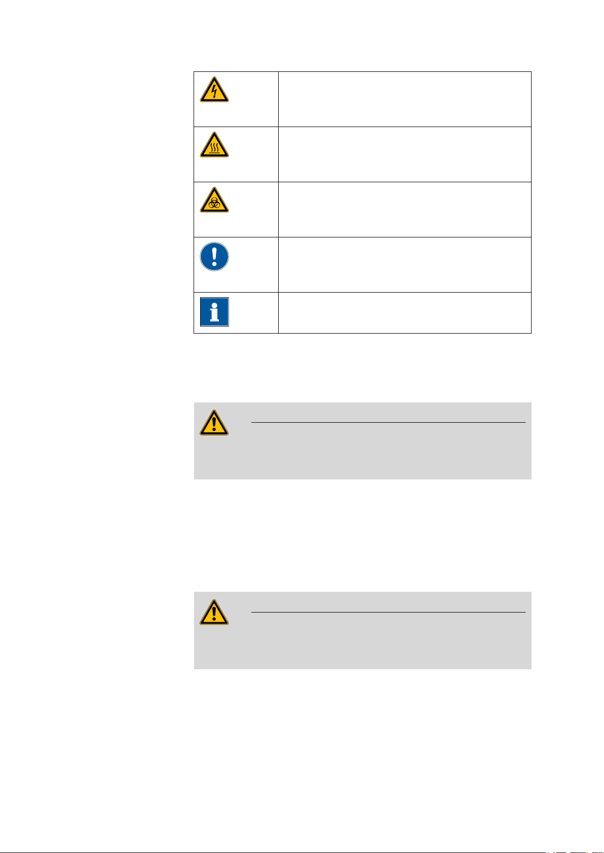
Warning
This symbol draws attention to a possible life hazard
or risk of injury.
■■■■■■■■■■■■■■■■■■■■■■ 1 Introduction
872 Extension Module IC Pump ■■■■■■■■ 3
Warning
This symbol draws attention to a possible hazard due
to electrical current.
Warning
This symbol draws attention to a possible hazard due
to heat or hot instrument parts.
Warning
This symbol draws attention to a possible biological
hazard.
Caution
This symbol draws attention to a possible damage of
instruments or instrument parts.
Note
This symbol marks additional information and tips.
1.3 Safety instructions
1.3.1 General notes on safety
Warning
This instrument may only be operated in accordance with the specifica-
tions in this documentation.
This instrument has left the factory in a flawless state in terms of technical
safety. To maintain this state and ensure non-hazardous operation of the
instrument, the following instructions must be observed carefully.
1.3.2 Electrical safety
The electrical safety when working with the instrument is ensured as part
of the international standard IEC 61010.
Warning
Only personnel qualified by Metrohm are authorized to carry out service
work on electronic components.
1.3 Safety instructions ■■■■■■■■■■■■■■■■■■■■■■
4■■■■■■■■ 872 Extension Module IC Pump
Warning
Never open the housing of the instrument. The instrument could be
damaged by this. There is also a risk of serious injury if live components
are touched.
There are no parts inside the housing which can be serviced or replaced
by the user.
Mains voltage
Warning
An incorrect mains voltage can damage the instrument.
Only operate this instrument with a mains voltage specified for it (see
rear panel of the instrument).
Protection against electrostatic charges
Warning
Electronic components are sensitive to electrostatic charges and can be
destroyed by discharges.
Always pull the mains cable out of the mains connection socket before
connecting or disconnecting electrical appliances on the rear panel of
the instrument.
1.3.3 Tubing and capillary connections
Caution
Leaks in tubing and capillary connections are a safety risk. Tighten all
connections well by hand. Avoid applying excessive force to tubing
connections. Damaged tubing ends lead to leakage. Appropriate tools
can be used to loosen connections.
Check the connections regularly for leakage. If the instrument is used
mainly in unattended operation, then weekly inspections are manda-
tory.
■■■■■■■■■■■■■■■■■■■■■■ 1 Introduction
872 Extension Module IC Pump ■■■■■■■■ 5
1.3.4 Flammable solvents and chemicals
Warning
All relevant safety measures are to be observed when working with
flammable solvents and chemicals.
■Set up the instrument in a well-ventilated location (e.g. laboratory
flue).
■Keep all sources of flame far from the workplace.
■Clean up spilled fluids and solids immediately.
■Follow the safety instructions of the chemical manufacturer.
1.3.5 Recycling and disposal
This product is covered by European Directive 2002/96/EC, WEEE – Waste
from Electrical and Electronic Equipment.
The correct disposal of your old equipment will help to prevent negative
effects on the environment and public health.
More details about the disposal of your old equipment can be obtained
from your local authorities, from waste disposal companies or from your
local dealer.

2.1 Front ■■■■■■■■■■■■■■■■■■■■■■
6■■■■■■■■ 872 Extension Module IC Pump
2 Overview of the instrument
2.1 Front
1
2
34
5
6
7
Figure 1 Front 872 Extension Module IC Pump
1Eluent degasser
See Chapter 4.5
2Coupling 6.2744.230
For connecting the eluent aspiration tubing.
3High pressure pump
See Chapter 4.6
4Purge valve
See Chapter 4.6
5Inline filter
See Chapter 4.7
6Pulsation damper
See Chapter 4.8
7Standby indicator

■■■■■■■■■■■■■■■■■■■■■■ 2 Overview of the instrument
872 Extension Module IC Pump ■■■■■■■■ 7
2.2 Rear
Made by Metrohm Herisau Switzerland
Out
In
Transport security screws
to Vacuum
234
1
Figure 2 Rear 872 Extension Module IC Pump
1Transport locking screws 2Connector In
To connect the extension module to the IC
instrument or to a previous extension mod-
ule.
3Connector Out
To connect an additional extension module.
4Connector to Vacuum
To connect the vacuum chamber of the
extension module to the vacuum chamber
of the IC instrument.

3.1 General ■■■■■■■■■■■■■■■■■■■■■■
8■■■■■■■■ 872 Extension Module IC Pump
3 Assembly
3.1 General
The extension modules are fitted directly to the 850 Professional IC instru-
ment and connected with it via 6.2156.060 connection cable. Extension
modules have no power supply of their own, but rather draw the electric-
ity they require from the instrument with which they are connected.
Up to three extension modules can be connected to an 850 Professional
IC instrument. The following restrictions are to be taken into account:
Restrictions The 850 Professional IC instruments and their extension modules must not
have more than 4 identical components in common, i.e.:
■a maximum of 4 high pressure pumps,
■a maximum of 4 peristaltic pumps,
■a maximum of 4 injection valves,
■a maximum of 4 suppressors (MSM, SPM incl.),
BUT
■only a maximum of 3 degassers
■and a maximum of 3 CO2 suppressors (MCS)
Note
If all 4 high pressure pumps are being used at once, then not all of
them are permitted to run at maximum flow for longer periods of time.
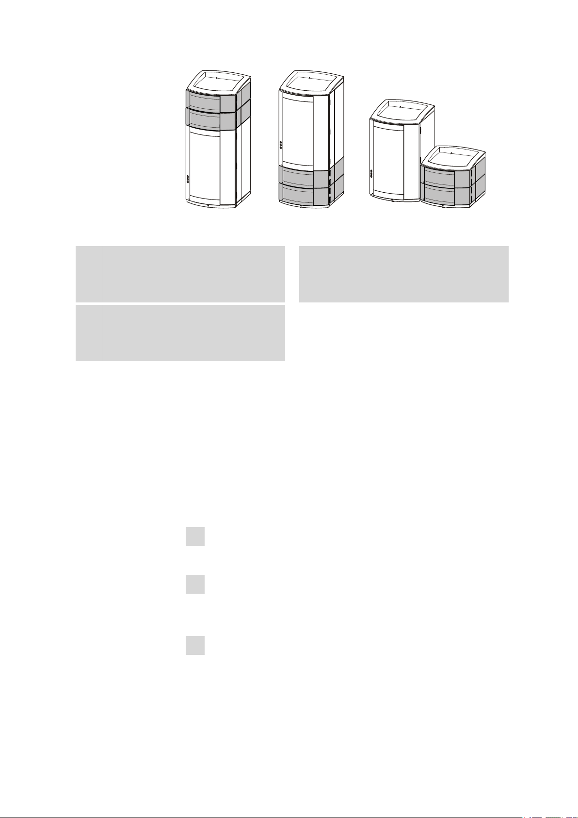
Extension modules can be mounted in the following setup versions:
■above, between instrument and bottle holder (3-A), or
■below, between instrument and base tray (3-B), or
■next to the instrument (3-C) with a separate 6.2061.110 base tray and
a 6.2061.100 bottle holder (to be ordered additionally). For this, the
longer 6.2156.070 connection cable (to be ordered additionally), is
necessary, too.
■■■■■■■■■■■■■■■■■■■■■■ 3 Assembly
872 Extension Module IC Pump ■■■■■■■■ 9
A B C
Figure 3 Setup versions
AExtension module above the IC instru-
ment
Between the 850 Professional IC and the
bottle holder.
BExtension module on the below the IC
instrument
Between the base plate and the 850 Profes-
sion IC.
CExtension module next to the IC instru-
ment
With its own base plate and its own bottle
holder next to the 850 bottle holder.
Position the extension module in such a way that the capillary connections
can be kept as short as possible. If several extension modules are used,
then they should all be installed in the same location if possible – either
above, below or next to the IC instrument. If this is not possible, then the
extension modules that are located at greater distances from one another
must be connected with one another by means of the longer 6.2156.070
connection cable (available as optional accessory).
3.2 Mounting the extension module onto the IC instru-
ment
1Switching off the IC instrument
Switch the IC instrument off and disconnect the mains cable.
2Clearing the bottle holder
If there are bottles and other items on the bottle holder, remove
them.
3Removing drainage tubings
Loosen the drainage tubing from the drainage tubing connector on
the bottle holder.

3.2 Mounting the extension module onto the IC instrument ■■■■■■■■■■■■■■■■■■■■■■
10 ■■■■■■■■ 872 Extension Module IC Pump
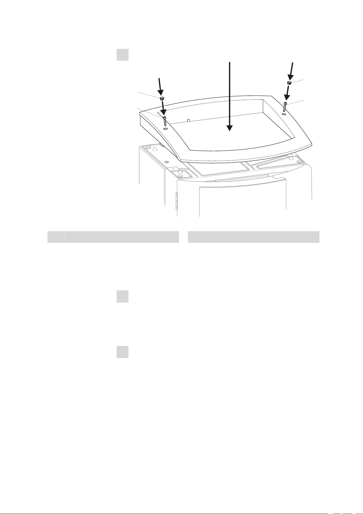
4Dismounting the bottle holder
1
2
1
2
Figure 4 Dismounting the bottle holder
1Cover stoppers 2Cylinder screws
■Remove covering stoppers (4-1).
■Loosen the cylinder screws with a 6.2621.100 3 mm hexagon
key.
■Remove the bottle holder
5Attaching the extension module(s)
Place the extension module(s) on the IC instrument.
■■■■■■■■■■■■■■■■■■■■■■ 3 Assembly
872 Extension Module IC Pump ■■■■■■■■ 11
6Mounting the bottle holder
1
2
1
2
Figure 5 Mounting the bottle holder
1Cover stoppers 2Cylinder screws
■Attach the bottle holder on the extension module.
■Tighten the cylinder screws (4-2) with an 6.2621.100 3 mm hexa-
gon key
■Insert covering stoppers (4-1).
7Connecting the extension module
■Plug a 6.2156.060 cable into the connector In of the extension
module and screw it tight.
■Plug the other end of the cable into the Extension module con-
nector of the IC instrument and screw it tight.
8Optional: Connecting a further extension module
■Plug the cable 6.2156.060 or a longer 6.2156.070 cable (optional
accessory) into the connector In of the second extension module
and screw it tight.
■Plug the other end of the cable into the Out connector of the first
extension module and screw it tight.

3.3 Mounting the extension module below the IC instrument ■■■■■■■■■■■■■■■■■■■■■■
12 ■■■■■■■■ 872 Extension Module IC Pump
9Mounting the drainage tubing
Reconnect the drainage tubing to the drainage tubing connector of
the bottle holder.
Possibly, a longer section of silicone tubing 6.186.020 must be cut to
fit and mounted (see also the manual for the IC instrument).
3.3 Mounting the extension module below the IC instru-
ment
1Switching off the IC instrument
Switch the IC instrument off and disconnect the mains cable.
2Clearing the bottle holder
If there are bottles and other things on the bottle holder, remove
them.
3Disconnecting all connections on the rear of the instrument
■Disconnect the mains cable,
■Disconnect the MSB cable,
■Disconnect the USB cable,
■Disconnect the leak sensor,
■Remove the drainage tubings.
4Removing the detector(s)
Disconnect the detector cable(s) and remove the detector(s) from the
IC instrument (see manual for the IC instrument).
5Removing the base tray
■Tilt the IC instrument sideways and lay it down flat.
■Loosen the cylinder screws with a 6.2621.100 3 mm hexagon
key.
■Remove base tray.
This manual suits for next models
1
Table of contents
Other Metrohm Water Pump manuals

Popular Water Pump manuals by other brands


AquaCare
AquaCare Turbo Chalk Reactor instruction manual

REHOBOT
REHOBOT PP70-9200RC operating instructions

Masterflex
Masterflex QUATTROFLOW 1200S OPERATING AND INSTALLATION Manual

Power-flo
Power-flo PFG2002HV Installation, Service Manual & Parts

Vortech
Vortech MP10 Setup guide

SPX
SPX Johnson Pump Ultima Bilge 800GPH instruction manual


