METRON Nano(+) User manual
ENGLISH
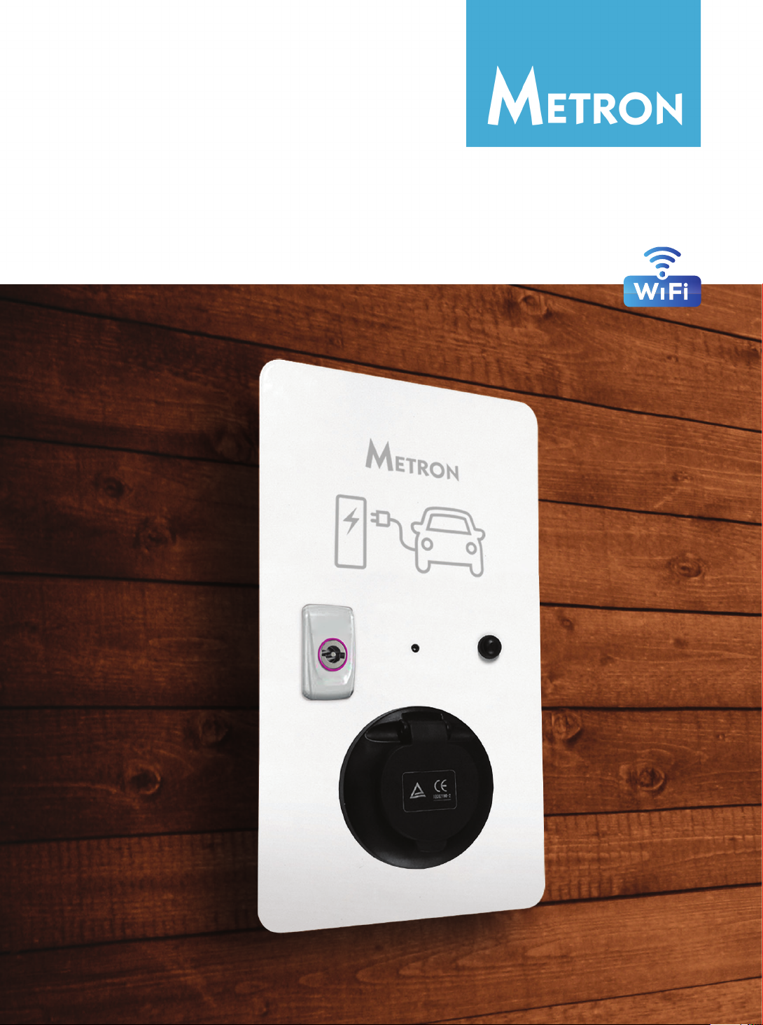
EV CHARGING STATION
USER MANUAL
About
Information about charging stations in the latest
version of this document, is available at
www.eauto.si/metron-shop
ILLUSTRATIONS
The illustrations provided in this document are for demonstration purposes only. Depending on charging
station options and market region, the information may appear slightly different.
PRODUCT SPECIFICATIONS
All specifications and descriptions contained in this document are verified to be accurate at the time of
printing. However, because continuous improvement is a goal at Metron, we reserve the right to make
product modifications at any time. To communicate any inaccuracies or omissions in this document, please
send an email to: info@eauto.si
2021 Metron Institute
All information in this document is subject to copyright and other intellectual property rights of Metron Institute
and its licensors. This material may not be modified, reproduced or copied, in whole or in part, without the
prior written permission of Metron Institute and its licensors. Additional information is available upon request.
For more information call +386 51 320 538
or
e-mail us at info@eauto.si

Contents
About………………………………………………..2
General………………………………………………………………………2
Safety………………………………………………………………………….2
Intended Use…………………………………………………………….2
Qualification of Personnel……………………………………….3
Product Description………………………………………………….3
Charging Connectors……………………………………………..4
Identification label……………………………………………………4
Exterior and Interior View Of
Typical Charging Station………………………………………….5
Technical specifications…………………………………………..6
Installation…………………………………………8
Choosing the charging station location…………………8
Unpacking the charging station………………………………8
Opening the charging station…………………………………9
Mounting on the wall – minimal
distance to devices/obstacles………………………………..9
Wall installation of the charging station………………..10
Electrical connection………………………11
Supply Voltage…………………………………………………………11
Safeguarding and personal protection………………….11
Connecting the supply line…………………………………….12
Operation………………………………………..13
Setting the charging current/power
via front button………………………………………………………..13
METRON Charge Control application
(standard for “+” models)……………………………………….14
Dynamic Power Control
(OPTIONAL for “+” models)…………………………………….16
Mode 3 Charging…………………………………………………….17
Terminating the charging process…………………………17
Status LED and
troubleshooting……………………………..18
Status LED…………………………………………………………………18
Maintenance…………………………………..19
Maintenance Plan……………………………………………………19
Disassembly, Storage and
Disposal…………………………………………..20
Disassembly……………………………………………………………..20
Storage…………………………………………………………………….20
Disposal……………………………………………………………………20
Warranty………………………………………….21
Limited Warranty……………………………………………………..21
Returning Devices……………………………………………………21
About
2EV Charging station user manual
General
This manual is an important aid for ensuring the fault-free and safe operation of the device. The specifications
in this manual apply only to the device stated in the product description. Read this manual before setting
up the device.
Using this manual will help you to:
• avoid any risks for the user;
• become acquainted with the device;
• achieve optimum functioning;
• promptly detect and rectify faults;
• avoid any malfunctions due to improper installation;
• cut down on repair costs and reduce the number of downtimes;
• improve the reliability and increase the service life of the system;
• avoid causing harm to the environment.
These instructions are an important part of the product and must be retained for future reference. METRON
accepts no liability for any damage resulting from non-observance of the information in this manual.
Safety
The device has been designed using state-of-the-art technology and is safe to operate.
Nevertheless, there may be residual risks associated with the device under the following circumstances:
• the device is not used as intended;
• non-compliance with the safety information given in this manual;
• the device is damaged;
• the device is not maintained properly;
• the device is modified or converted improperly;
• the maintenance work specified in this manual is not carried out in due time.
Warning: Risk of death resulting from non-compliance with documentation! Any person authorized
to work on the system must have read and understood this manual, in particular the “Safety” chapter.
The electrical installation, initial operation and servicing of the device may only be performed by qualified
electricians, who have been authorized by the operator.
Intended Use
The device may be used for the purpose described in “Product Description” on page 3 and in conjunction
with the supplied and approved components. Any use exceeding the aforementioned shall be deemed
unintended. METRON assumes no liability for damage resulting from non-intended use. Intended use also
includes:
• compliance with all the information in this manual;
• carrying out of servicing tasks according to schedule.
The device may present hazards, if not used as intended.

3EV Charging station user manual
About
Qualification of Personnel
The electrical installation, setup and maintenance of the device may only be performed by qualified
electricians, which have received authorization from the system operator to perform such tasks. Such
persons must have read and understood the operating manual and must comply with the information
therein.
Requirements of qualified electricians:
• knowledge of general and special safety and accident prevention guidelines;
• knowledge of relevant electrical guidelines (e.g., DIN VDE 0100 section 600 DIN VDE
0100722), as well as valid national regulations;
• the ability to recognize risks and avoid possible dangers.
Product Description
METRON range of charging stations (Nano(+), Standard(+) and Duo(+)) is unique for its robustness and
durability with close to zero maintenance. It is designed to charge electric vehicles and is supplied either
with a Type 2 socket or on cable Type 2/Type 1 plug with various charging power capabilities. Nano,
Standard and Duo are classic heavy duty charging station with basis functions. Nano+, Standard+ and Duo+
are advanced charging stations with WiFi Charge Control app. and can be equipped with special Metron
Dynamic Power Control system which protects the main household fuse and allow solar SURPLUS charging
where the house has a solar power plant installed.
The METRON charging station is meant to be used in private and semi-public areas, such as company car
parks, depots or private land.
The charging station is used exclusively for charging electrically powered vehicles.
• Mode 3 charging according to IEC 61851-1:2010.
• Plugs and sockets according to IEC 62196.
Basic features of METRON charging stations:
• Communication with EV through METRON Micro EVSE 1 or Micro EVSE 3 control unit
• Status information through LED
• Push button for setting charging current
• Durable steel casing with aluminum front panel
• Simplified maintenance – hinged front panel opens with a key
• Modular robust design – every component can be tested and/or replaced, separately
• Built-in WEB SERVER with preloaded METRON Charge Control app. & WiFi connectivity
(standard for “+” models)
• Dynamic Power Control system (optional for “+” models)
• RFID charging enable (optional for “+” models)
• MID certified Energy meter (optional for all models)
• Spiral cable (optional for all models)
• Type 2 socket with locking mechanism (optional for all models)
• Type 2 plug holder – protects conductive parts of the plug from water, insects and other filth
(optional for all models, holder location can be per customer request)
• Type 2 plug with integrated Tesla remote for opening charge port and unlocking the plug
(optional for all models)

About
4EV Charging station user manual
Charging Connectors
Depending on the version, the charging station is equipped with one of the following connector systems:
1.
2.
3.
4.
5.
6.
7.
8.
9.
10.
Manufacturer
Type
Supply voltage and charging current settings
Temperature operating range
Country of origin
Web page
Serial number
Production year
Certification mark
Protection class
1.
2.
3.
Charging socket Type 2 for Mode 3 charging.
Permanently connected charging cable with charging connector Type 2.
Permanently connected charging cable with charging connector Type 1.
Identification label

5EV Charging station user manual
About
Exterior and Interior View Of Typical Charging Station
Lock
LED indicator
Push button
Socket (optionally with Type 2/Type 1 plug)
METRON Micro EVSE 1 or Micro EVSE 3 charge controller
Charge controller power supply fuse
Charging fuse
Residual current protection device (RCCB)
Charging contactor
MID certified energy counter (OPTIONAL)
Earth terminal
1.
2.
3.
4.
5.
6.
7.
8.
9.
10.
11.

About
6EV Charging station user manual
Technical specifications
Nano(+) Standard(+) Duo(+)
Charging station plug/
socket type
type 2 / type 1 (IEC 62196
/ SAE J1772)
female plug or type 2
charging socket
type 2 / type 1 (IEC 62196
/ SAE J1772)
female plug or charging
socket
type 2 / type 1 (IEC 62196
/ SAE J1772)
female plug or charging
socket
Max. charging power 3,7 kW or 7,4 kW
(1-phase)
11 kW or 22 W (3-phase) 2 x 3,7 kW or 2 x 7,4 kW
(1-phase), 2 x 11 kW or
2 x 22 kW (3-phase)
Max. charging current 16 A or 32 A* 3x16 A or 3x32 A* 2 x 3x16 A or 2 x 3x32 A*
Possible charging
current settings (by
user)
6/8/10/13/16/20**/25**/
32**A via front button,
“+” models from 6A in
1A steps to 16A or 32A
via WiFi Charge Control
app.
6/8/10/13/16/20**/25**/
32**A via front button,
“+” models from 6A in 1A
steps to 16A or 32A via
WiFi Charge Control app.
6/8/10/13/16/20**/25**/
32**A via front button,
“+” models from 6A in
1A steps to 16A or 32A
via WiFi Charge Control
app. (separate for each
socket / plug)
Rated Voltage 230 Vac 230 Vac/400 Vac 230 Vac/400 Vac
Operating voltage/
frequency range
from 90 V up to 270 V
(50/60 Hz)
from 90 V up to 270 V
(phase voltage)
(50/60 Hz)
from 90 V up to 270 V
(phase voltage)
(50/60 Hz)
Cable length (if ordered
with plug and cable)
5m*** / premium quality
according to EV charge
cable standard EN 50620
5m*** / premium quality
according to EV charge
cable standard EN 50620
5m*** / premium quality
according to EV charge
cable standard EN 50620
Spiral cable optional for all models optional for all models optional for all models
Circuit breaker/fuse Yes Yes Yes
Residual-current device
type B or type A + 6mA
DC (FID/RCCB)
Yes Yes Yes
WiFi Metron Charge
Control app.
standard for “+” models standard for “+” models standard for “+” models
Dynamic Power Control
system
standard for “+” models standard for “+” models standard for “+” models
RFID charging enable optional for “+” models optional for “+” models optional for “+” models
MID certified Energy
meter
optional for all models optional for all models optional for all models
Type 2 charging socket
with locking mechanism
optional for all models
with type 2 socket
optional for all models
with type 2 socket
optional for all models
with type 2 socket
Type 2 plug holder optional for all models optional for all models optional for all models

7EV Charging station user manual
About
Nano(+) Standard(+) Duo(+)
Tesla remote for
opening charge port
and unlocking the plug
– integrated in Type 2
plug
optional for all models
with type 2 plug
optional for all models
with type 2 plug
optional for all models
with type 2 plug
Supported WiFi
standards
IEEE 802.11b/g/n
(“+” models only)
IEEE 802.11b/g/n
(“+” models only)
IEEE 802.11b/g/n
(“+” models only)
WiFi speed up to 150 Mbit/s
(“+” models only)
up to 150 Mbit/s
(“+” models only)
up to 150 Mbit/s
(“+” models only)
WiFi security WPA2
(“+” models only)
WPA2
(“+” models only)
WPA2
(“+” models only)
WiFi signal range up to 20 m
(“+” models only)
up to 20 m
(“+” models only)
up to 20 m
(“+” models only)
UV resistance Yes (all parts) Yes (all parts) Yes (all parts)
Operating ambient air
temperature range
from -30°C to +50°C from -30°C to +50°C from -30°C to +50°C
Maximum operating
altitude
2000m 2000m 2000m
Relative ambient
humidity (operational
and storage)
max 95 %
(without condensation)
max 95 %
(without condensation)
max 95 %
(without condensation)
Storage temperature From -40 °C up to +70
°C
From -40 °C up to +70
°C
From -40 °C up to +70
°C
Minimum required
power supply cable
cross section
3G2,5 mm2 for 3,7 kW
3G6 mm2 for 7,4 kW
5G2,5 mm2 for 11 kW
5G6 mm2 for 22 kW
2x5G2,5 mm2 for 2 x 11
kW, 2x5G6 mm2 for 2 x
22 kW
Weight Approx. 8-10 kg Approx. 8-10 kg Approx. 10-12 kg
* Exact max charging power and configuration information can be found on the product information label
which is located on the right-hand side of the charging station.
** Charging current setting depends on the order and setting it above 16 A is only possible on 32A rated
charging stations.
*** Cable length is not fixed and can be customized on order.
Caution: Due to internal overvoltage protection installed in some components of the charging
station the regular insulation tests are allowed to be performed with max. 250 Vac/50-60 Hz test
voltage. If higher insulation test voltage is used the charging station can be permanently damaged!

8 Installation
Installation
Unpacking the charging station
Caution: Damage to the charging station may incur by improper handling. Collisions and impacts
may damage the charging station.
• Move the charging station with caution.
• Use a soft base to set aside the charging station.
Warning: Mortal danger posed by improper installation. There is a risk of injury for persons
performing tasks for which they are neither qualified nor have received appropriate training.
• The device may only be installed by personnel which are familiar with the task, have been
instructed with regard to the associated hazards and who possess the necessary qualifications.
• Before installing, all safety requirements must be met.
Choosing the charging station location
Warning: Risk due to unsuitable environmental conditions / installation locations. Unsuitable ambient
conditions and installation locations may lead to dangerous situations when dealing with electricity.
Please observe the following points when selecting a location to install charging station:
• Do not install in potentially explosive atmospheres (e.g., gas refueling stations).
• Do not install in flood-prone areas.
• Comply with local technical connection requirements and safety rules.
• For ambient conditions see “Technical specifications” table.
• The charging system must be protected from direct exposure to water jets.
• The mounting surface must have sufficient strength to withstand the mechanical stresses.
When mounting on plasterboard walls they must have at least two layers.
1.
2.
3.
4.
Charging station
User manual
Warranty
Key
9
Installation
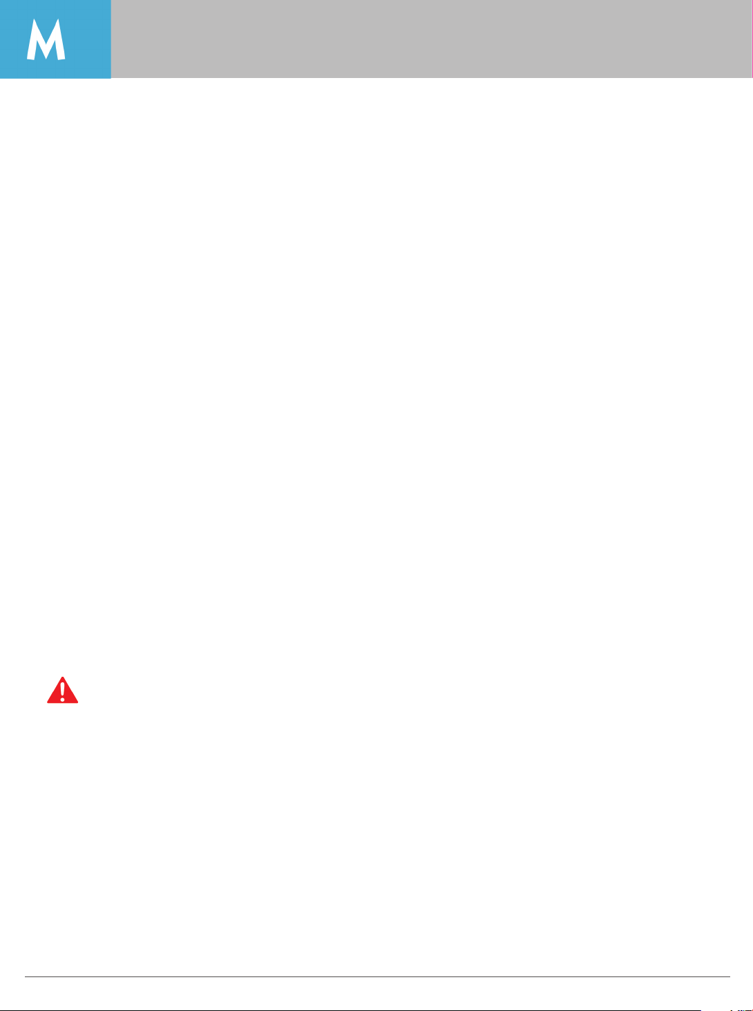
Opening the charging station
Installation
Mounting on the wall – minimal distance to devices/obstacles
Maintain the specified minimum distances for unrestricted access during operation, maintenance and
repair. The dimensions are given in mm.
300
300
300 300
1.
2.
3.
4.
Insert the key in the keyhole.
Turn the key clockwise.
When the key is in vertical position, the charging station is unlocked.
Open the front panel.
10 Installation
Installation
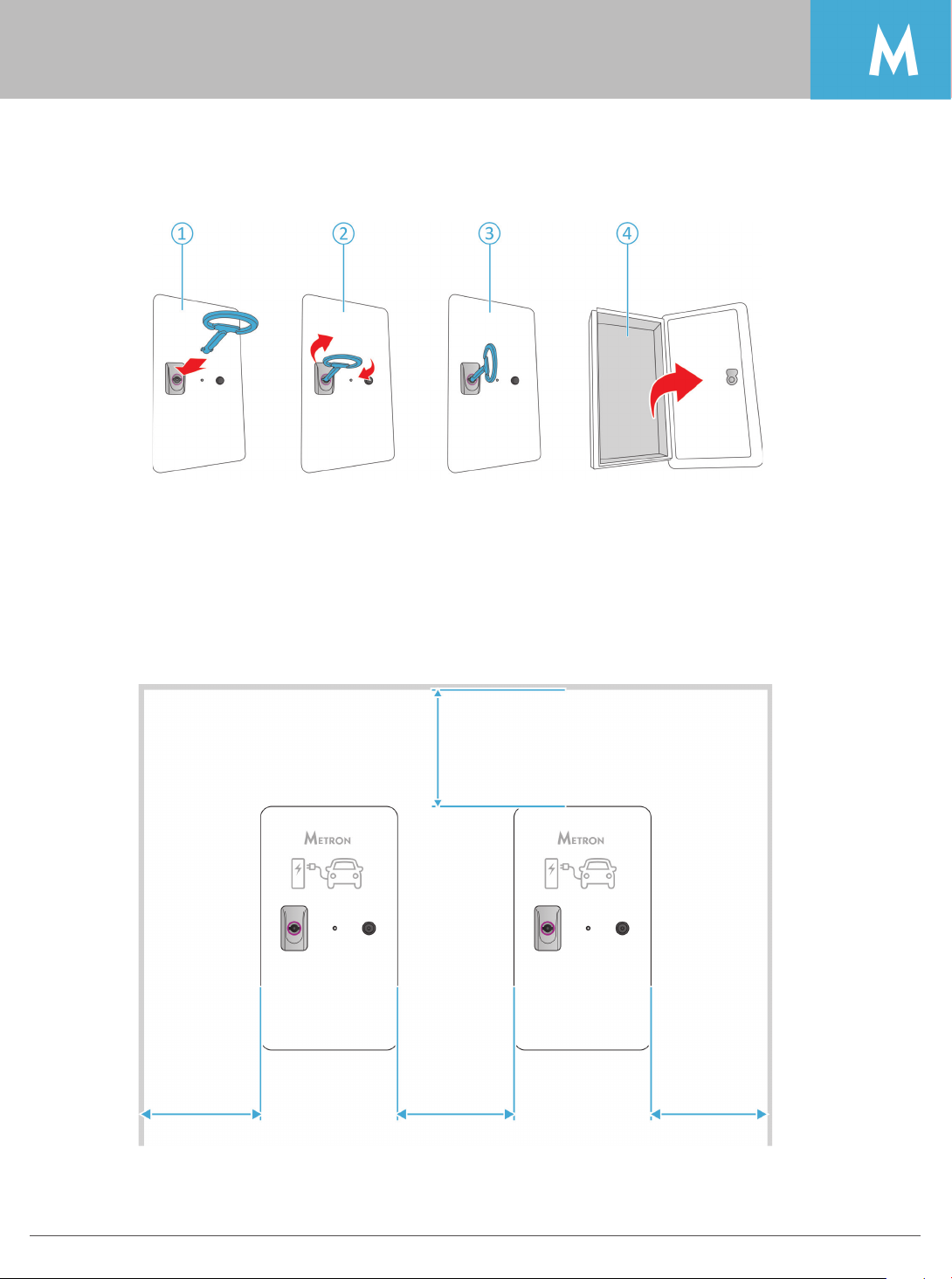
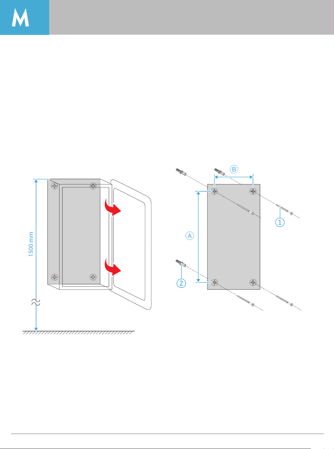
Wall installation of the charging station
A suitable on-site mounting method must be chosen, depending on the installation surface (concrete,
brick, wood, etc.).
METRON recommends the installation of the charging station at a height (up to the top edge of the casing)
of approximately 1.50 meters above the finished floor.
Make certain that charging station has been fitted firmly and securely.
A
Nano(+) 260 mm
Standard(+) 260 mm
Duo(+) 360 mm
B
Nano(+) 110 mm
Standard(+) 130 mm
Duo (+) 260 mm
1.
2.
3.
Mark the mounting holes
Drill the holes in the wall
Secure the charging station to the wall by using dowels and screws
1.
2.
Dowels
Screws

11Electrical connection
Electrical connection
Supply Voltage
Warning: Risk of death by electric shock! Components have voltage applied. Contact with current
conducting parts results in an electric shock, burns or death. When working with the electrical
system, the following procedure must be followed:
• Disconnect device from voltage.
• Secure the device from being turned back on.
• Ensure that no voltage is applied.
• Earth and short-circuit the device.
• Cover neighboring components that are under voltage and secure the danger area.
Consider the following when connecting to the power supply:
• Abide by the national/local regulations.
• Ensure a clockwise rotating field for a three-phase connection.
Safeguarding and personal protection
Warning: Danger to life by electric shock. Residual current circuit breakers (type B) sensitive to
universal currents may be installed instead of residual current circuit breakers (type A) sensitive to
pulse currents. In accordance with IEC 61851 standard, all charging stations are fitted with residual
current device (RCD).
Warning: Fire hazard due to device overload.
Fire hazard due to device overload in case of wrong design of the on-site circuit breaker. The
normal current of the selected circuit breaker must not exceed the specifications on the nameplate .
Warning: Risk of injury or death when incorrectly installed. Risk of injury if installation is done by
unqualified personnel.

12 Electrical connection
Electrical connection
Connecting the supply line
1. Strip the supply cable over a length of 370 mm and remove the core insulation over a length of 12 mm.
2. Connect the cores of the supply cable to the RCCB ①and the earth core to the terminal ②. The
protective earth conductor ③ must be longer than all other conductors.
3. Check that the individual cores are properly connected and that the screws are tightened.
4. Turn the reset lever ④to position ①to power the system.
Maximum conductor circumference in the power supply cable: 10 mm2
Warning: Risk of injury
There is a risk of injury due to damage to the charging system.
If it appears that, the charging system cannot be operated safely:
• Take the charging system out of service.
• Determine and eliminate any faults/malfunctions.
• Contact your electrician, local dealer or direct factory help.
13Operation
Operation
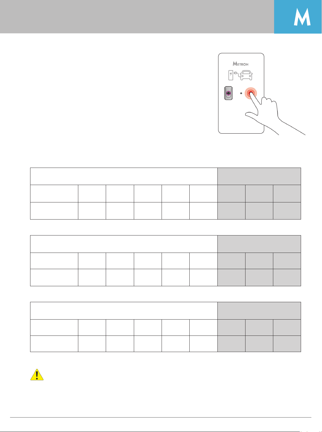
Setting the charging current/power via front button
This setting enables you to set the maximum charging current, with which your electric vehicle will be
charging.
Nano(+) 3,7 kW Nano(+) 7,4 kW
Number of LED
blinks 1 2 3 4 5 6 7 8
Charging
current/power
6 A
1,4 kW
8 A
1,8 kW
10 A
2,3 kW
13 A
3,0 kW
16 A
3,7 kW
20 A
4,6 kW
25 A
5,8 kW
32 A
7,4 kW
Standard(+) 11 kW Standard(+) 22 kW
Number of LED
blinks 1 2 3 4 5 6 7 8
Charging
current/power
3x6 A
4,1 kW
3x8 A
5,5 kW
3x10 A
6,9 kW
3x13 A
9,0 kW
3x16 A
11,0 kW
3x20 A
13,8 kW
3x25 A
17,4 kW
3x32 A
22 kW
Duo(+) 2 x 11 kW Duo(+) 2 x 22 kW
Number of LED
blinks 1 2 3 4 5 6 7 8
Charging
current/power
2x3x6 A
2x4,1 kW
2x3x8 A
2x5,5 kW
2x3x10 A
2x6,9 kW
2x3x13 A
2x9,0 kW
2x3x16 A
2x11,0 kW
2x3x20 A
2x13,8 kW
2x3x25 A
2x17,4 kW
2x3x32 A
2x22 kW
Caution: charging power setting is stored on on-board memory and remains unchanged
(even if power supply is disconnected) until new setting is entered. When turned on, the
charging station will inform the user of its current setting with the corresponding number of
blinks (from 1 to 8).
1.
2.
3.
Press and hold the push button (blue LED switches off
immediately).
After 5 seconds LED starts blinking slowly.
Releasing the push button after a certain number of blinks
determines the setting (see example on page 18).
14 Operation
Operation
METRON Charge Control application (standard for “+” models)
In order to connect to the WiFi METRON Charge Control application you need to do the following:
• Make sure the charging station is energized (connected to power).
• Go to WiFi menu in your smart phone, tablet or laptop PC and search for WiFi networks.
• Find “METRON Station 1” network and connect to it; enter the WiFi password 12345678 (this is default - it
is recommended that you change it in the METRON Charge Control application).
• Scan QR code you find on the charging station and follow the link (it will open your default web
browser and launch the Metron Charge Control automatically; OR open your favorite web browser and
go to the following IP address: http://192.168.4.4
• The METRON Charge Control application will be loaded immediately. Up to 5 users (devices) at a
time can be wirelessly connected to the charging station and all connected devices will automatically
receive all the latest data; for example, if one user changes the charging current with the slider all others
will see that on their screens.
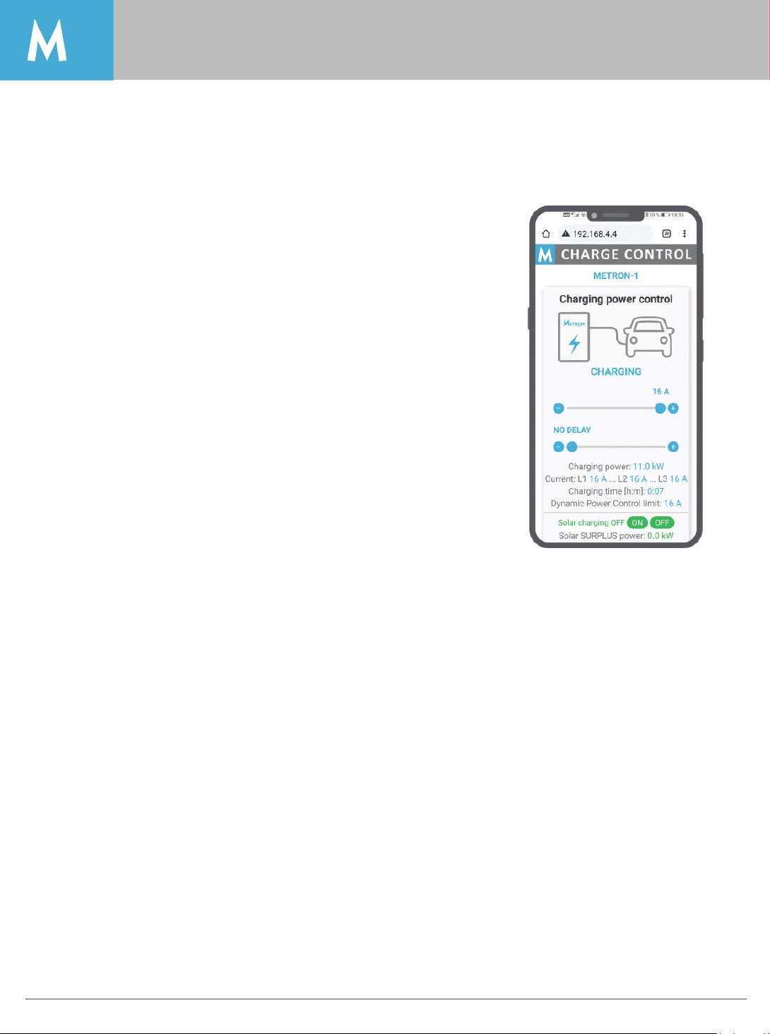
The web-based METRON Charge Control application functions:
• User can set the desired charging current and delay charging start.
• User can turn on/off solar SURPLUS charging if solar power plant
is installed.
• User can see all the real time measurements of charging power,
charging current and charging energy.
• Allows the user to change WiFi password and WiFi name (ssid).
• Allows the user to connect the charging station to local WiFi
network and also set the charging station internet access in the
WiFi router (advanced users).
• Allows OVER THE AIR application UPDATES via WiFi by manufacturer, certified installer or even advanced
user.
• If dynamic charging with house main fuse protection is enabled/connected the user can also see
house load, house energy consumption, solar power and solar energy production.
Metron charging stations with “+” mark have a built-in WiFi access point
with web server what enables users to connect to it wirelessly by any
smart phone, tablet or laptop PC. As there is a web server inside with
preloaded METRON Charge Control application you don’t need to install
any additional program/application on your device because the METRON
Charge Control runs in your favorite web browser (Google Chrome,
Microsoft Edge, Mozilla Firefox…) on any operating system (Google
Android, Apple iOS, Microsoft Windows, Huawei HarmonyOS, Linux…)
you have on your smart phone, tablet or laptop PC.

15
Operation
Operation
If you forget the WiFi password you’ve set, you (or installer) need to do the following:
• Disconnect the charging station’s power, open the Micro EVSE 3 EV charge controller box to see the
electronic printed circuit board.
• Energize the charging station and carefully (without touching anything else) press the small tact button
marked as “PB1” for 2-3 seconds; WiFi name (ssid) is reset to default value “METRON Station 1” and
forgotten password is reset to default value 12345678 but it’s not yet activated.
• To activate default WiFi password (and default WiFi name) you need to disconnect power wait for a
few seconds and turn the power back on.
The METRON Charge Control application is intuitive and usually doesn’t need more instructions to be used;
just browse and explore the functions (some important user instructions are explained where the additional
user info is required). If you don’t understand something please feel free to contact Metron.

16 Operation
Operation
Caution: Detailed schematics for installing METRON Dynamic Power Control system are located in a
separate installation manual, intended for qualified installers only.
Dynamic Power Control (OPTIONAL for “+” models)
All “+” charging stations can be equipped with METRON Dynamic Power Control system that is always
monitoring the load at house main fuse with electric current sensors and dynamically adjusting (lowering
or rising) the charging current/power of your electric vehicle in the way the main house fuse never gets
overloaded (never blows-up). If the house has a solar (or wind/hydro) power plant installed this system
allows higher current/power charging than would be allowed by the main fuse and it also enables the
possibility of user activated solar SURPLUS charging what means the vehicle will be charged only with
excess solar power without taking any energy from the grid. METRON Dynamic Power Control system is
designed to work with 1-phase and 3-phase power systems.
To be short, METRON Dynamic Power Control system enables users to charge their electric vehicle
without worrying about the load other household appliances might draw from the in-house grid.
There are 3 options for installing Dynamic Power Control system (main fuse protection):
A) If there is 1 charging station in the house the current sensors can be installed at main fuse location
and hardwired to the charging station.
B) If there is 1 charging station in the house and it’s not possible to hardwire the current sensors all the
way to the charging station, the current sensors can be connected to additional locally installed
METRON Dynamic EV Charging Unit (model 3FD-2) that is sending data wirelessly to the charging
station.
C) If there are 2 or more charging stations installed in the house and powered from the one main fuse
only wireless Dynamic Power Control system can be established. All you need is 1 pcs METRON
Dynamic EV Charging Unit (model 3FD-2) and current sensors. This way up to 30 charging stations
can be controlled and main fuses with rated current up to 250A are supported.
Note: Wireless signal has an open-air space range of 500m with buint-in antenna and up to 2000m with
additional antennas on the METRON Dynamic EV Charging Unit (model 3FD-2) and also on the charging
station. If the system is installed within one house usually no additional antennas are needed.
Current Sensor Wire
EV Charging Station
CIRCUIT
BREAKER
F4 F3 F2 F1F5

17Operation
Operation
Mode 3 Charging
The charging station performs now the following steps automatically:
• Detecting the current-carrying capacity of the charging cable with resistance coding. Unsuitable
charging cables are rejected.
• It checks that the requirements for proper charging have been met.
• Communicating with the vehicle using the CP contact. The charging current upper limit is
communicated to the vehicle. The protective earth connection is checked at the same time.
• The vehicle signals the charging station that it is ready for charging. The charging process starts.
• The status LED slowly blinks.
• The maximum available charging current depends on the following points:
• Power rating of the charging station.
• Features/version of the charging station.
• Current load capacity of the charging cable.
Terminating the charging process
Caution: To terminate the charging process we recommend that you interrupt the charging with
your vehicle FOB key or any other vehicle key that stops the charging. We do not recommend that
you unplug the cable from the station during the charging.
Warning: Make sure that vehicle and charging cable are suitable for mode 3 charging.
1. Connect the charging cable to the vehicle.
2. Insert the plug of the charging cable completely into the charging socket type 2 at the charging
station (only for charging stations with integrated charging socket type 2).

18 Troubleshooting
Status LED and troubleshooting
LED status Information/Cause Fix
LED is not on or blinking There is no power to the charging
station, the LED is faulty or charge
controller is faulty.
Check the activation of fuse/circuit
breaker or residual current circuit
breaker (RCCB); check charge
controller fuse/circuit breaker.
If not successful the charging
station needs a service.
Rapid blinking
(plugged or unplugged)
Station or vehicle fault. Try to charge another electric
vehicle; if other vehicle doesn’t
charge the charging station
needs a service.
Status LED
The status LED displays the operating status/faults of the charging station.
Faults:
Warning: If you cannot fix the error or fault, ask a qualified electrician to check the charging station.
LED status Information
Slow blinking immediately after
turning-on the charging station
Blinks indicate last set charging current setting via front button.
Constantly on when plug is
unplugged
Stand-by/Ready to charge
Slow blinking when plugged in Charging in progress.
Constantly on when plugged in Electric vehicle is fully charged.
Slow blinking 2 times when plug is
plugged in
Electric vehicle requests interior ventilation (charging is halted).
Slow blinking 4 times
(plugged in or not plugged in) -
Only applicable for versions with
METRON Dynamic Power Control
system.
Charging not possible/interrupted to protect main grid fuse.
Other power devices switched on (water heaters, ovens, washing
machines…). Restarts charging automatically when those power
consumers are switched off.
Other manuals for Nano(+)
1
This manual suits for next models
2
Table of contents
Other METRON Batteries Charger manuals

 User manual")


 User manual")


