METRON TOWER/STANDARD+ User manual
Page1
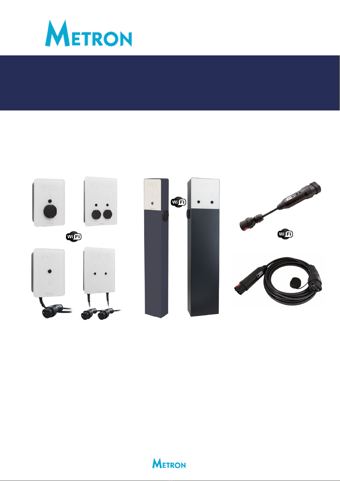
SMARTwallmounted,standaloneandportablechargingstationswithWiFi
TOWER/STANDARD+&TOWER/DUO+withOCPP&RFID
PC03X+&PC04X+&PC05X+&PC02Y+&PC04Y+&PC05Y+
QUICKINSTALLATIONGUIDE
rev.7,12.10.2023‐‐‐applicablefor:
MicroEVSE3chargingcontrollercodeversion(wallmounted/standalonestations):v3.07
WiFiMETRONChargeControlapplicationversion(wallmounted/standalonestations):v1.08
OCPP/RFIDmodulecodeversion(wallmounted/standalonestations):v1.07
MicroEVSE4chargingcontrollercodeversion(portablestations):v4.02
WiFiMETRONChargeControlapplicationversion(portablestations):v2.03
3FD‐3DYNAMICEVCHARGINGUNITcodeversion(3FD‐3unit):v3.00
WiFiMETRONDynamicPowerControlapplicationversion(3FD‐3unit):v3.00
1. Mountthestation(3or4screws)(applicableforwallmountedandstandalonestations).
2. Connectthestationto230/400Vac50Hz(L1,L2,L3,N,PE)powersupply(wallmountandstandalonestations).
3. ApplythepowersupplyandobservetheblinkingofbluestatusLEDonthefrontsideofthestation.Thenumber
ofblinksindicatesthemaximumchargingpowertowhichthestationhasbeenset(1blink=6A,2=8A,3=10A,
4=13A,5=16A,6=20A,7=25A,8=32A).
4. Testthefunctionalityofmanualchargingcurrentsettingbypressingthepushbuttononthefrontpanel(blue
statusLEDOFF)andkeepitpressed.After5secondsthebluestatusLEDstartstoblink(keepitpressed).Count
thenumberofallblinks.AfterthelastblinkthebluestatusLEDwillswitchOFFandyoucanreleasethebutton.
16Achargingstationsmaximumnumberofblinksis5;32Aversionshaveall8blinks.
5. ExplaintotheclientthatblinkingbluestatusLEDrepresentscharginginprogress,statusLEDONmeansthat
thevehicleisnotconnectedorcharginghasalreadybeencompleted.
6. Explaintotheclientthattheycansetthemaximumchargingcurrentiftheypressthebuttonandcountthe
bluestatusLEDblinks.Thesetvalueissavedintothememoryandstayssavedalsoincaseofpowerloss.
7. Explainanddemonstratetheclienthowtoconnecttobuilt‐inWiFiwebserverandwhatcapabilitiesthebuilt‐it
MetronChargeControlapplicationprovides.
www.eauto.si[email protected]+38651320538

Page2
Metronwallmounted,standaloneandportablechargingstationswith“+”markhaveabuilt‐inWiFiaccesspointwith
webserverwhatenablesuserstoconnecttoitwirelesslybyanysmartphone,tabletorlaptopPC.Asthereisaweb
serverinsidewithpreloadedMETRONChargeControlapplicationyoudon'tneedtoinstallanyadditionalapplication
onyourdevicebecausetheMETRONChargeControlrunsinyourfavoritewebbrowser(GoogleChrome,MicrosoftEdge,
MozillaFirefox,...)onanyoperatingsystem(GoogleAndroid,AppleiOS,MicrosoftWindows,HuaweiHarmonyOS,
Linux,...)youhaveonyoursmartphone,tabletorlaptopPC.
Theweb‐basedMETRONChargeControlapplicationfunctions:
•Usercansetthedesiredchargingcurrentanddelaychargingstart
•Usercanturnon/offSOLARSURPLUSchargingifsolarpowerplantisinstalled
•Usercanseealltherealtimemeasurementsofchargingpower,chargingcurrentandchargingenergy
•Usercansetactivationrequirementforchargingstarttolockthestationforunauthorizedusers
•Usercanset/activateGUESTMODE(passwordrequired)whichpreventstheuserstochangesettings(applicablefor
wallmountedstations)
•AllowstheusertochangeWiFipasswordandWiFiname(ssid)foraccessingtheChargeControlapp.
•AllowstheusertoconnectthechargingstationtolocalWiFinetworkandalsosetthechargingstationinternetaccess
intheWiFirouter(advancedusers),
•AllowstheusertoestablishconnectiontoOCPPbackendserverviaWiFiorETHERNETandread/storeRFIDcards
(applicablefor“+”wallmountedstationswithOCPP/RFIDmoduleinstalled),
•AllowsOVERTHEAIR(OTA)UPDATESoftheapp.firmwareviaWiFibymanufacturer,certifiedinstalleroruser,
•Ifhardwiredorwirelessdynamicchargingwithhousemainfuseprotectionisenabled/connectedtheusercanalsosee
houseload,houseenergyconsumption,solarpowerandsolarenergyproduction.
InordertoconnecttotheWiFiMETRONChargeControlapplicationyouneedtodothefollowing:
•Makesurethewallmountedorportablechargingstationisenergized(connectedtopower).
•GotoWiFimenuinyoursmartphone,tabletorlaptopPCandsearchforWiFinetworks.
•Find“METRONStation1”(wallmountedstations)or“METRONPortable1”(portablestations)networkandconnect
toit;entertheWiFipassword12345678(thisisdefault‐itisrecommendedthatyouchangeitintheMETRONCharge
Controlapplication).
•ScanQRcodeyoufindonthestationandfollowthelink(itwillopenyourdefaultwebbrowserandlaunchtheMetron
ChargeControlautomatically;ORopenyourfavoritewebbrowserandgotothefollowingIPaddress:http://192.168.4.4
•TheMETRONChargeControlapplicationwillbeloadedimmediately.
Upto5users(devices)atatimecanbewirelesslyconnectedtothechargingstationandallconnecteddeviceswill
automaticallyreceiveallthelatestdata;forexample,ifoneuserchangesthechargingcurrentwiththesliderallothers
willseethatontheirscreens.
IftheuserforgetstheWiFipasswordyouneedtodothefollowing:
•Disconnectthewallmountedorportablechargingstationfrompower,pressthe“PushButton”andkeepitpressed.
•Connectthestationtopower.
•ThebluestatusLEDstartsblinking2times.
•After30secondsthestatusLEDwillturn‐onfor3secondsandthenturn‐of.
•Releasethe“PushButton”andWiFiname(ssid)&passwordareresettodefaultvalues.
TheMETRONChargeControlapplicationisintuitiveandusuallydoesn’tneedmoreinstructionstobeused;justbrowse
andexplorethefunctions(someimportantuserinstructionsareexplainedwheretheadditionaluserinfoisrequired).
Ifyoudon’tunderstandsomethingpleasefeelfreetocontactMetronsupportanytime.
METRONwallmounted,standaloneandportablechargingstationscanbeequippedwithhardwired(wallmounted
andstandaloneonly)orwirelessDYNAMICEVCHARGINGsystemwhichenableschargingwithmainfuseprotection
andincaseofinstalledsolar/wind/hydropowerplantalsosolar/wind/hydroSURPLUSchargingandPOWERFUL
chargingthataddssolar/wind/hydropowertomainfuserating.Ifyouareinstallingsuchachargingstationplease
carefullyreadtheguidelinesonthenextpages.

Page3
1. AfterinstallingthechargingstationasdescribedonthePage1installthesuppliedcurrentmeasuring
transformers(CT)onthehouse/buildingmainpowersupplyinputandconnectthemtoMicroEVSE3DYNAMIC
WiFiEVchargecontrollerasshownontheME3‐1or/andME3‐2drawingsintheattachment.
2. SwitchONchargingstationpowersupply.
3. SettheneededparametersviaMetronChargeControlapplication.Onthefirstpageclick/presson“Settings”
buttonandscrolldownto“Essentialparameters”windowwhereyouseethesettings.Press“Change
parameters”buttonandenterthepassword“param2011”inordertobeabletochangesettings.Thenchange
settingsasneeded/requiredandpress“Confirm”buttonbelowtosavenewsettings.
4. DESCRIPTIONOFEACHESSENTIALPARAMETERtheinstallercanset:
GeneralNOTE:Onceconfirmedthesetvaluesstay
savedintheinternalmemorypermanently(power
lossdoesn’tdeletesettings).
HARDWIRED1or3‐phaseMAINFUSEprotectionDYNAMICcharging
with1WALLMOUNTEDorSTANDALONEchargingstationpermainfuse
Select1,2or3phasepowerplantgridconnection.
Defaultsetting:3phases
Select1,2or3phasehousegridconnection.
Defaultsettin
g
:3
p
hases
Selectmainfuseratingfrom1Ato80Aincaseof
hardwiredmainfuseprotection.Incaseofwireless
dynamicpowercontrolisestablishedthissettingshall
besetto35Aandtheactualrelevantfuseisthenset
onwirelessdynamicEVchargingunit.
Defaultsetting:35A
Selectifactivation/autenticationforchargingstart
(RFID,OCPPbackend,viaWiFiapp.,etc)isneededor
not.Ifyouselect“No”thestationwillstartcharging
immediatelyafterthevehicleisconnected‐
Plug&chargeprinciple.
Defaultsetting:No
Set“Hardwired”incasecurrentsensorsareconnected
directlytoMicroEVSE3controlleror“Wireless”if
additionalMetronDynamicEVchargingunitisused.
Defaultsetting:Hardwired
StationID(identification)isusedforoptimizedand
prioritizedwirelessmainfuseprotectiondynamic
charging.Possiblesettingsarefrom1to150what
meansamaximumof150stationscanbesmartly
controlledbythe3FD‐3dynamicEVchargingunit.
Lowernumbermeanshigherpriority.Youneedto
selectdifferentIDforeachbythe3FD‐3controlled
wallmountedorportablechargingstation.
Defaultsetting:1
Thereare25channelsavailableinordertoprevent
interferenceofwirelesssignalincase2ormore
DynamicEVchargingunitsareinstallednearby(e.g.
twoneighbourhouses).MicroEVSE3DYNAMICWiFi
controllerandDynamicEVchargingunitneedstobe
settothesamechannelinordertowork.
Defaultsetting:channel1
Frontbuttoncanbeenabledordisabled.Incasethe
stationisforpublicuseitisrecommendedtodisable
thefrontbutton.
Defaultsetting:Enabled

Page4
5. Testthe3/1‐phasemainfuseprotectiondynamiccharging:
ConnecttoWiFiandgototheMetronChargeControlweb‐basedapplication.Connecttheelectricvehicleto
thechargingstationandobservethechargingcurrentmeasurementsinWiFIChargeControlapp.under
“Advancedinfo”.Intentionallyputthebigloadtoeachofthephases(onebyone)tosurpassthemainfuse
ratedcurrentandobserveifthechargingcurrentdecreasedinthewaythetotalmainfusecurrentisnothigher
thanmainfuseratedcurrent.Todothatyouneedtoconnectpowerfulloadtoeachphase(easiestwayisto
useregular2kWelectricheaters–1,2,3…connectedinparallel.
6. Explaintotheclientthatthechargingstationwillautomaticallyreduceorstopthechargingincaseofmain
fuseoverload.IncaseofcharginginterruptionbecauseofoverloadthebluestatusLEDwillblink4times(with
pauseafter4blinks)untiltheloadonthemainfuseislowenoughtoresumecharging.Themainfusecurrent
onthemostloadedphaseneedstobeapp.7Alowerthanratedfusecurrentinorderthechargingstationwill
allowchargingtostart/resume.ThestatusLEDcanblink4timesevenifthevehicleisnotconnected.Thiswill
informtheuserthatthechargingcannotstartuntiltheotherpowerfulhouseloadsareswitched‐off.
7. Explaintotheclientthatincaseofinstalledsolar/wind/hydropowerplantthechargingstationallowsvehicle
chargingwithhigheroverallcurrentthanthesetnominalmainfusevalue(thisfunctiondoesn’tworkatnight
ofcourse).ThisfeatureisactiveonlyincaseSolar/wind/hydropowerplantphases=Housegridconnection
phases.

Page5
1. InstallthechargingstationasdescribedonthePage1.
2. SwitchONchargingstationpowersupply.
3. Setthemainfuseratingto35A(neededonlyifithasbeenchanged‐factorydefaultsettingisalready35A)via
MetronChargeControlapplicationasdescribedonPage3.
4. Forwallmountedandstandalonechargingstationssethousemainfuseprotectionrealizationto“Wireless”
viaMetronChargeControlapplicationasdescribedonPage3(bydefaulttheit’ssetto“Hardwired”what
meansRFreceiverisnotactivated).
5. IfnecessarysettheotheressentialparametersasdescribedonPage3.
6.
Installandsetthe3FD‐3DYNAMICEVCHARGINGUNITasdescribedonpages7,8and9orolder
3FD‐2DYNAMICEVCHARGINGUNITasdescribedinQUICKINSTALLATIONGUIDErev.4.3FD‐3and
3FD‐2unitsarecompatible,thedifferenceisinmax.fuserating(3FD‐2upto250A,3FD‐3upto1000A)
andmax.numberofcontrolledchargingstations(3FD‐2cancontrolupto30stations,3FD‐3up150
stations).
WIRELESS1or3‐phaseMAINFUSE
protectionDYNAMICchargingwith1or
moreWALLMOUNTEDor/and
STANDALONEchargingstations

Page6
1. Connectthesmartportablechargingstationtowallsocket(applythepowersupply).
2. SettheneededparametersviaMetronChargeControlapplication.Onthefirstpageclick/presson“Settings”
buttonandscrolldownto“Essentialparameters”windowwhereyouseethesettings.Press“Change
parameters”buttonandenterthepassword“param2011”inordertobeabletochangesettings.Thenchange
settingsasneeded/requiredandpress“Confirm”buttonbelowtosavenewsettings.
3. DESCRIPTIONOFEACHESSENTIALPARAMETERtheinstallercanset:
4. Installandsetthe3FD‐3DYNAMICEVCHARGINGUNITasdescribedonpages7,8and9orolder
3FD‐2DYNAMICEVCHARGINGUNITasdescribedinQUICKINSTALLATIONGUIDErev.4.3FD‐3and
3FD‐2unitsarecompatible,thedifferenceisinmax.fuserating(3FD‐2upto250A,3FD‐3upto1000A)
andmax.numberofcontrolledchargingstations(3FD‐2cancontrolupto30stations,3FD‐3up150
stations).
WIRELESS1or3‐phaseMAINFUSEprotectionDYNAMIC
chargingwith1ormorePORTABLEchargingstations
GeneralNOTE:Onceconfirmedthesetvaluesstay
savedintheinternalmemorypermanently(power
lossdoesn’tdeletesettings).
Select1,2or3phasepowerplantgridconnection.
Defaultsetting:3phases
Select1,2or3phasehousegridconnection.
Defaultsettin
g
:3
p
hases
Selectifactivationforchargingstartbypressingthe
“Activatecharging”buttononthefirstpageinMetron
ChargeControlapplicationisneededornot.Ifyou
select“No”theportablechargingstationwillstart
chargingimmediatelyafterthevehicleisconnected‐
Plug&chargeprinciple.
Defaultsetting:No
Wirelessfuseprotectionchargingcanbemanually
enabledordisabled.Ifyouchoose“Disabled”the
portablechargingstationwillalwayschargewiththe
current/poweryousetbysliderorviafrontbuttonand
willnot“listen”the3FD‐3dynamicEVchargingunit
evenifitwillbewithinthewirelessrange.
Defaultsetting:Enabled
StationID(identification)isusedforoptimizedand
prioritizedwirelessmainfuseprotectiondynamic
charging.Possiblesettingsarefrom1to150what
meansamaximumof150stationscanbesmartly
controlledbythe3FD‐3dynamicEVchargingunit.
Lowernumbermeanshigherpriority.Youneedto
selectdifferentIDforeachbythe3FD‐3controlled
wallmountedorportablechargingstation.
Defaultsetting:1
Thereare25channelsavailableinordertoprevent
interferenceofwirelesssignalincase2ormore
DynamicEVchargingunitsareinstallednearby(e.g.
twoneighbourhouses).MicroEVSE3DYNAMICWiFi
controllerandDynamicEVchargingunitneedstobe
settothesamechannelinordertowork.
Defaultsetting:channel1
Page7
1. ActivatewirelessFUSEprotectionDYNAMICchargingonwallmountedstation(s)asdescribedonPage3
(smartportablestationshaveenabledwirelessdynamicchargingRFreceiverbydefault).Youalsoneedtoset
housephasesandsolarphasesbutdon’tchangethemainfuseratingonthewallmountedstation(leave
default35Aorsetinbackto35Aifithasbeenchanged).
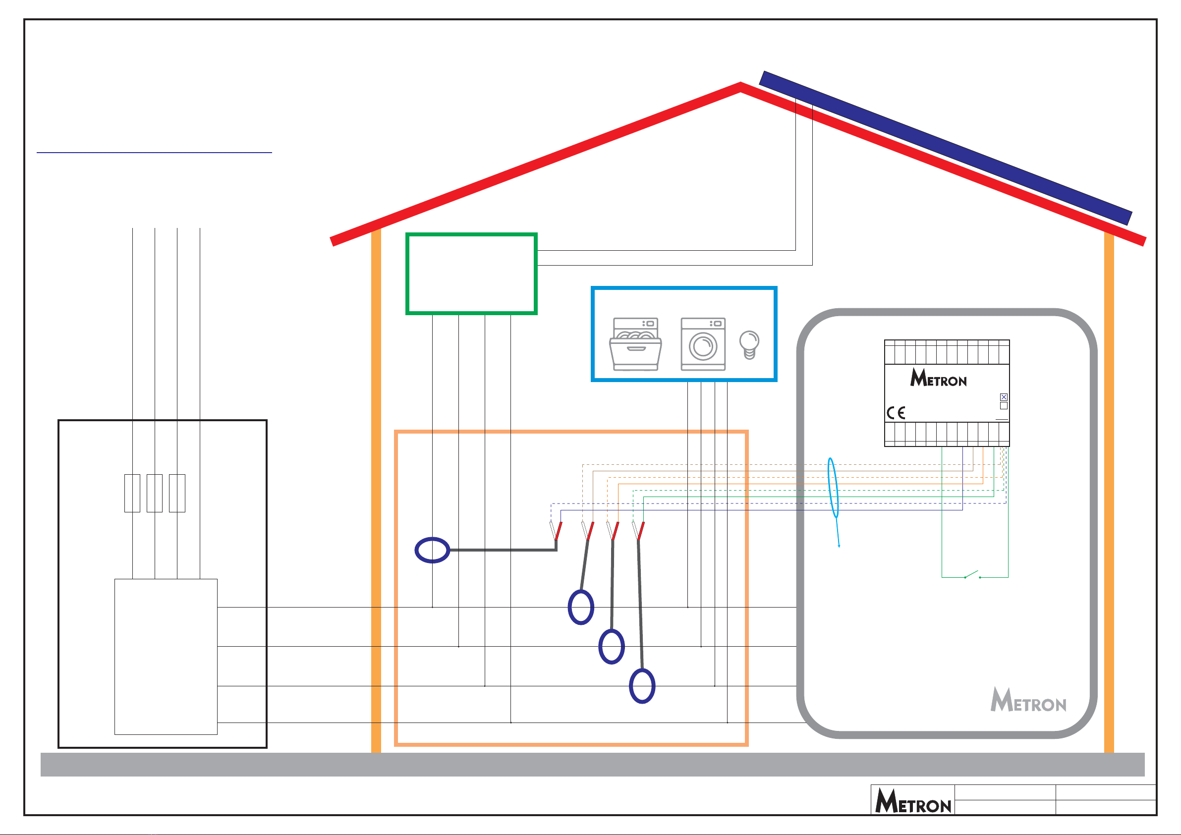
2. Installthe3FD‐3DYNAMICEVCHARGINGUNITandsuppliedcurrentmeasuringtransformers(CT)onthe
house/buildingmainpowersupplyinput(inthehousemaindistributionpanel)asshownonthe3FD‐3‐1
or/and3FD‐3‐2drawingsintheattachment.
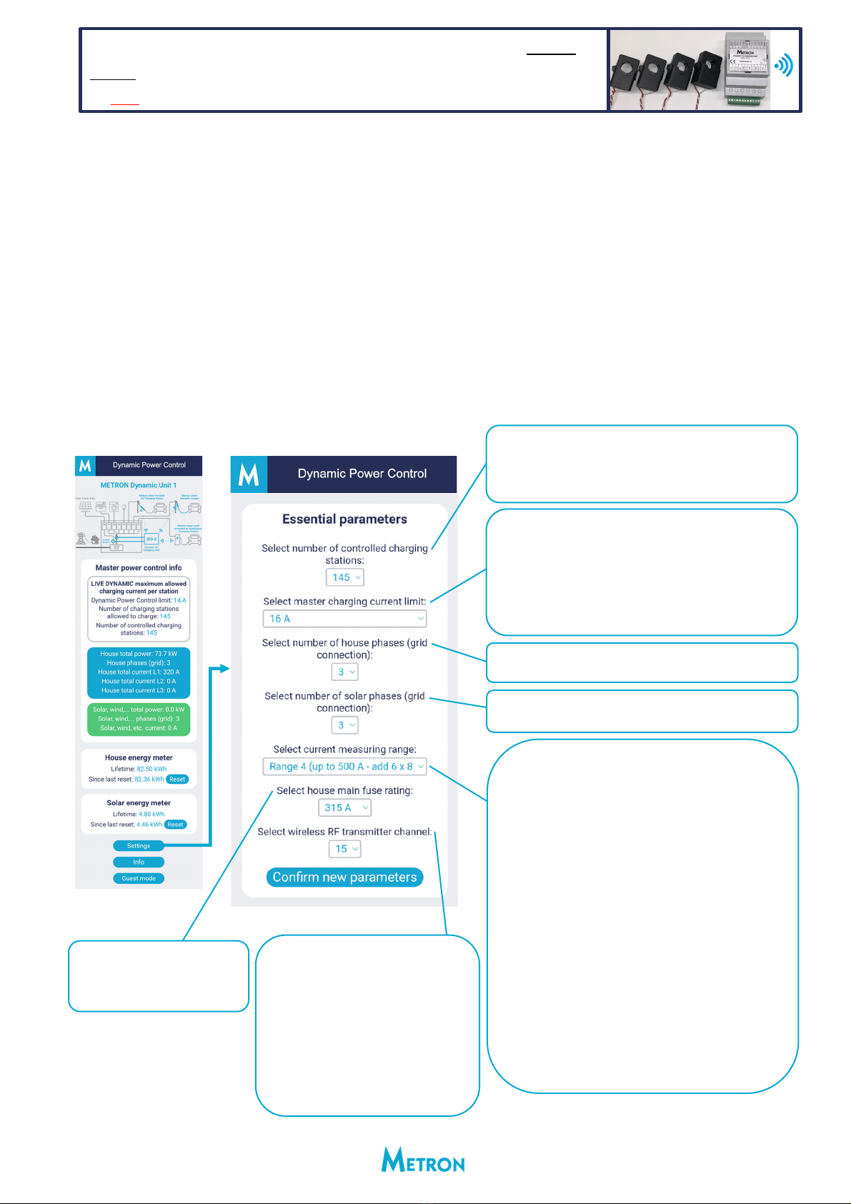
3. SettheneededparametersviaMetronDynamicPowerControlapplication.YouentertheDynamicPower
ControlapplicationthesamewayasChargeControlapplicationonstations(seeinstructionsonpage2)except
thatdefaultWiFiname(ssid)isinthiscase“METRONDynamic1”.Onthefirstpageclick/presson“Settings”
buttonandscrolldownto“Essentialparameters”windowwhereyouseethesettings.Press“Change
parameters”buttonandenterthepassword“param2011”inordertobeabletochangesettings.Thenchange
settingsasneeded/requiredandpress“Confirmnewparameters”buttonbelowtosavenewsettings.
4. DESCRIPTIONOFEACHESSENTIALPARAMETERtheinstallercanset:
INSTALLINGthe3FD‐3DYNAMICEVCHARGINGUNITfor1or3‐
phaseMAINFUSEprotectionWIRELESSDYNAMICchargingofup
to150wallmountedandportablechargingstationspermainfuse
Select1,2or3phasepowerplantgridconnection.
Defaultsetting:3phases
Select1,2or3phasehousegridconnection.
Defaultsettin
g
:3
p
hases
Selecthousemainfuserating‐
from1Ato1000A.
Defaultsetting:35A
Selectcurrentmeasuringrange:
‐Range1:upto80A(nofurtheractions,use
suppliedCTs)
‐Range2:upto160A(connect1additional84.5
Ohmresistorbetweeneachcurrentmeasuring
inputandGND)
‐Range3:upto250A(connect2additional84.5
Ohmresistorsbetweeneachcurrentmeasuring
inputandGND)
‐Range4:upto500A(connect6additional84.5
Ohmresistorsbetweeneachcurrentmeasuring
inputandGND)
‐Range5:upto1000A(connect12additional84.5
Ohmresistorsbetweeneachcurrentmeasuring
inputandGND)
Defaultsetting:Range1
Note:ForRange2,3,4,5youcanuseappropriate
currentratingcurrentmeasuringtransformers
(CTs).CTcurrentratioshallbe2000:1inallcases.
Thereare25channelsavailablein
ordertopreventinterferenceof
wirelesssignalincase2ormore
DynamicEVchargingunitsare
installednearby(e.g.twoneighbour
houses).DynamicEVchargingunit
andallwirelesslycontrolledcharging
stationsshallbesettothesameRF
channelinordertowork.
Defaultsetting:channel1
Selectnumberofstationsthe3FD‐3willcontrol.Upto
150wallmountedandportablechargingstationscanbe
controlledbyoneDynamicEVChargingUnit.
Defaultsetting:1chargingstation
SelectMASTERchargingcurrentlimitintherangeof
6Ato32A.Thissettingrepresentsabsolutemaximum
allowedchargingcurrentoneachbythis3FD‐3unit
controlledstation.Thereisalsoadditionalsetting0A
whichstopschargingonallwirelesslycontrolled
stationsbythis3FD‐3unit.
Defaultsettin
g
:32A
GeneralNOTE:Onceconfirmed
thesetvaluesstaysavedinthe
internalmemorypermanently
(powerlossdoesn’tdelete
settings).

Page8
5. Incasetherearemorethan1WALLMOUNTEDAND/ORPORTABLEstation(s)tobecontrolledbythe3FD‐3
DYNAMICEVCHARGINGUNITsetthenumberofchargingstationsasdescribedonPage7.Atthesametime
youneedtosettheparameterstationIDforeachwallmountedorwirelesschargingstation(seePage3and
6)inthewayeachchargingstationhasitsownIDstartingfrom1.Example:youhave3chargingstations
connectedtothesamemainfuse;settheIDonfirstoneto1,secondoneto2andonthethirdoneto3.The
stationIDisdisplayedintheWiFiChargeControlapp.in“Advancedinfo”menu.TheDYNAMICfuseprotection
chargingworksalsoincaseyouhaveaMIXEDconfiguration‐1ormorewallmountedand1ormore
portablestationspoweredfromthesamemainfuse!
6. Testthe3/1‐phasewirelessmainfuseprotectiondynamiccharging:ConnecttoWiFiandgototheMetron
ChargeControlapplicationononeofthewirelesslycontrolledchargingstations.Connecttheelectricvehicle
tothechargingstationandobservethechargingcurrentmeasurementsinWiFIChargeControlapp.under
“Advancedinfo”.Intentionallyputthebigloadtoeachofthephases(onebyone)tosurpassthemainfuse
ratedcurrentandobserveifthechargingcurrentdecreasedinthewaythetotalmainfusecurrentisnothigher
thanmainfuseratedcurrent.Todothatyouneedtoconnectpowerfulloadtoeachphase(easiestwayisto
useregular2kWelectricheaters–1,2,3…connectedinparallel).SimultaneouslyyoucanconnecttoMetron
Dynamicpowercontrolapplicationonthe3FD‐3unitandobserverealtimeload/currentstherealso.
7. Ifthereisnosignalfromthe3FD‐3unitdetectedonthechargingstationside(youcanseethatinformation
intheWiFiMetronChargeControlapplicationunder“Advancedinfo”)thewallmountedchargingstationwill
stopchargingandthefrontbluestatusLEDwillblink4timesasincaseofmainfuseoverloadconditionbut
theportablechargingstationwillcontinuechargingwithuserselectedchargingcurrent/power–thisfunction
islogicalforportablestationsbecausewhenyouchargesomewhereelsewhere3FD‐3unitisnotpresentits
purposeistocharge.
CommunicationsignaldetectiononwallmountedstationscanalsobeobservedifLED2isconnectedbetween
terminal20andGNDontheMicroEVSE3DYNAMICWiFiEVchargecontrollerinthechargingstation(signal
present=LED2on;nosignal=LED2off).PortablestationshaveSIGNALLEDalreadyinstalled.
8. Extendingthewirelessrangeof3FD‐3DYNAMICEVCHARGINGUNIT:incasethe3FD‐3andcontrolled
stationsarefarawayfromeachother(50m+airdistance)ortherearethickconcretewallsinbetweenthe
signalmaybetooweak.Butthereare2waysofextendingthewirelessrange:
‐Installexternal433MHzantennaonastation(s).Usepliersandcut‐offthebuilt‐inantenna.Antennashall
beinstalledontheoutsidewallandconnectedwithattachedcabletotheMicroEVSE3DYNAMICWiFiEV
chargecontroller.Usepliersandcut‐offthebuilt‐inantenna.Thisisthemosteffectivewaytoextend
signalrange.Note:Itisnotpossibletoinstalladditionalantennaonportablestations.
‐Installadditional433MHzantennaon3FD‐3DYNAMICEVCHARGINGUNIT.Usepliersandcut‐offthe
built‐inantenna.Thisantennaalsohelpsextendtherangebutit’slesseffective.
9. Explaintotheclientthat3FD‐3DYNAMICEVCHARGINGUNITdistributesthechargingpowertoallwirelessly
controlledchargingstationsequally.However,theclientcanstilladjustthechargingpoweroneachstation
viafrontbuttonorviacurrentsettingsliderinWiFiMetronChargeControlapplication.
10. Explaintotheclientthatincaseofwirelesslycontrollingonlyone(1)chargingstationitwillautomatically
reducechargingpowerorstopthechargingincaseofmainfuseoverload.Incaseofcharginginterruption
becauseofoverloadthestation’sfrontbluestatusLEDwillblink4times(withpauseafter4blinks)until
theloadonthemainfuseislowenoughtoresumecharging.Themainfusecurrentonthemostloaded
phaseneedstobeapp.7Alowerthanratedfusecurrentinorderthe3FD‐3willallowchargingto
start/resume.ThebluefrontstatusLEDcanblink4timesevenifthevehicleisnotconnected.Thisinforms
theuserinadvancethatchargingcannotstartuntiltheotherpowerfulhouseloadsareswitched‐off.
11. Explaintotheclientthatincaseofwirelesslycontrollingtwo(2)ormorechargingstationsitwillautomatically
reducethechargingpoweronallthestationsincaseofmainfuseoverload.Ifthatisnotenoughitwillstop
chargingononeormorechargingstationsstartingwiththeonewithhigheststationIDnumber.Incaseof
charginginterruptionbecauseofoverloadtheaffectedstation’sfrontbluestatusLEDwillblink4times(with
pauseafter4blinks)untiltheloadonthemainfuseislowenoughtoresumecharging.Ifthemainfuseistoo
overloadedbyotherloadsitwillstopchargingonallthestations.Aftertheloadonmainfuseisreducedthe

Page9
chargingwillberesumedstartingonthestationswithlowerstationIDnumbers(lowerstation’sIDnumbers
havethepriorityoverthehigherstation’sIDnumbers).Themainfusecurrentonthemostloadedphaseneeds
tobeapp.nx7Alower(n=numberofstationsthatwillbeallowedtoresumecharging)thanratedfusecurrent
inorderthe3FD‐3willallowchargingtostart/resumeontheadditionalnchargingstations.Thebluefront
statusLEDononeormorestationscanblink4timesevenifthevehicle(s)is(are)notconnected.Thisinforms
theuserinadvancethatchargingcannotstartuntiltheotherpowerfulhouseloadsareswitched‐off.
12. Explaintotheclientthatincaseofinstalledsolar/wind/hydropowerplantthe3FD‐2DYNAMICEVCHARGING
UNITallowsvehiclechargingwithhigheroverallcurrentthanthesetnominalmainfusevalue(thisfunction
doesn’tworkatnightofcourse).ThisfeatureisactiveonlyincaseSolar/wind/hydropowerplantphases=
Housegridconnectionphases.
13. ExplaintotheclientthatincaseofusingtheaPORTABLECHARGINGSTATIONPC03X+/PC04X+/PC05X+on
2ormoredifferentplaces(e.g.theclienthas2houses)itispossibletoinstallthe3FD‐3DYNAMICEV
CHARGINGUNITson2ormoredifferentlocations(e.g.2houses)withdifferentmainfusesandthenjust
move/usethesamePORTABLECHARGINGSTATIONonthosedifferentlocationsandhaveeverywheresafe
wirelessFUSEprotectionDYNAMICcharging.ThePORTABLECHARGINGSTATIONconnectsautomaticallyto
3FD‐3DYNAMICEVCHARGINGUNITateverylocation.
Page10
1. MicroEVSE3DYNAMICWiFiOCPPchargecontrollersupportsOCPP1.6communicationprotocolcompliant
connectionofthechargingstationtoanyOCPPbackendsystem.OCPP1.6communicationprotocolisused
forchargingmanagement.MostusedOCPPfunctionalitiesareimplementationofpaymentforchargingby
RFIDcard/readingQRcode,etcorjustmonitorthechargingenergyandchangingthechargingpower.Italso
allowstheoperators/userstoseestationstate(carconnected,charging,chargingcomplete),chargingpower,
chargingcurrent,chargingenergy,manuallyactivateorstopcharging,unlockingthechargingconnector,
resettingtheOCPPmoduleandevenperformover‐the‐air(OTA)updatesoftheOCPPfirmwareifneeded.
AllthoseOCPP1.6functionsaresupportedbyMetronMicroEVSE3DYNAMICWiFiOCPPchargecontroller.
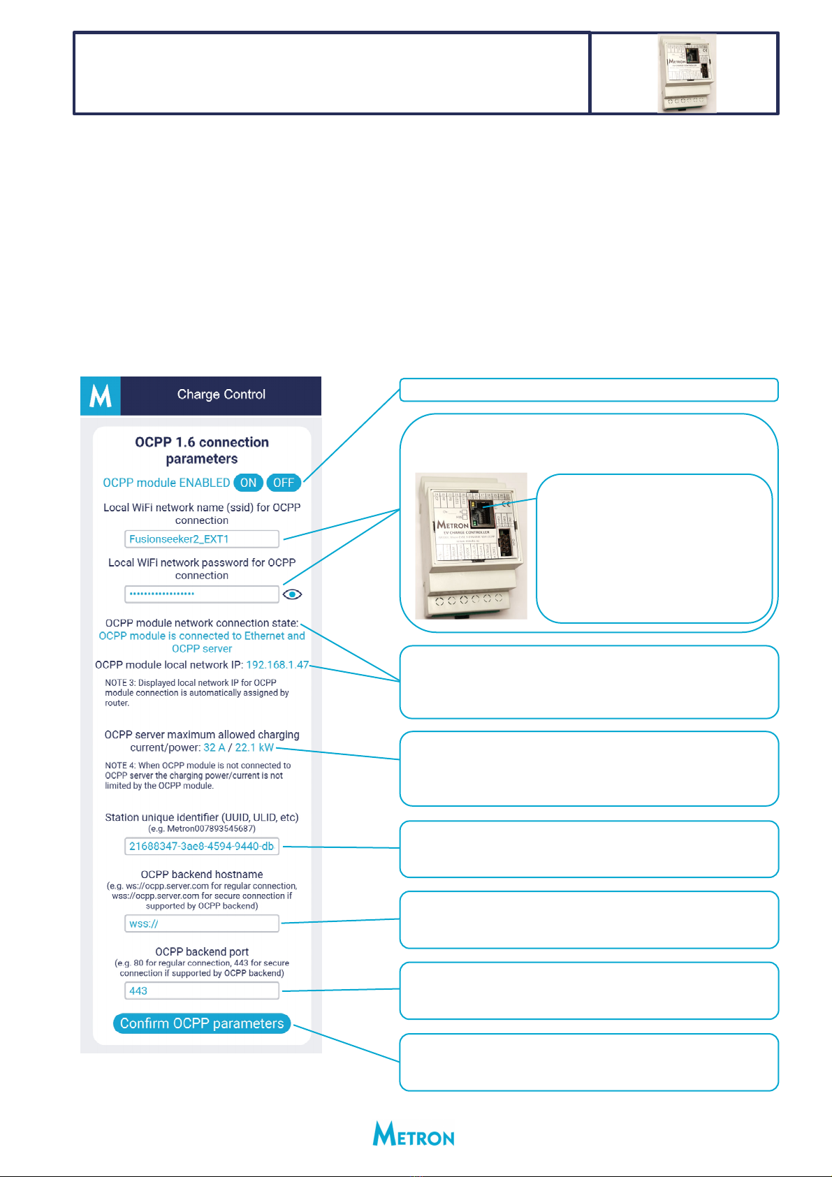
2. AllneededsettingsregardingOCPP1.6connectioncanbesetviaMetronChargeControlapplication.Onthe
firstpageclick/presson“Settings”buttonandscrolldownto“OCPP1.6connectionparameters”window.
3. DESCRIPTIONOFOCPPPARAMETERStheinstallercanset:
OCPP1.6managementwith
MicroEVSE3DYNAMICWiFIOCPPchargecontroller
GeneralNOTE:Onceconfirmedtheset
valuesstaysavedintheinternalmemory
permanently(powerlossdoesn’tdelete
settings).
OCPPmodulecanbeenabledordisabled.
InsertWiFissid&passwordincaseyouwanttoconnectOCPPto
theinternetviaWiFi.Theotherwaytoconnectittotheinternetis
viaEthernetport:
HereyougetinfoaboutOCPPconnection–connectedtointernetvia
WiFiorEthernetandinformationiftheOCPPmoduleisconnectedto
OCPPserver.LocalnetworkIPisalsodisplayedifit’sconnectedto
localnetwork.
OCPPbackendsystemcancontrolthechargingpowerifneededor
requested.Ifthereisnochargingpower/currentlimitationprovided
byOCPPbackendamaximumpossiblestationchargingpoweris
s
h
o
wn.
Hereyouenterthestationuniqueidentifierwhichcanbeprovidedby
OCPPbackendoperatorortheOCPPbackendoperatorallowsyouto
setyourownidentifier.
HereyouenterportnumberyougetfromOCPPbackendoperator.If
youdon’tgetitthenjustdeleteeverythingandleavetextboxblank.In
caseofsecurewebsocketconnectiontheportnumberisalways443.
IfyouconnecttheEthernetcableto
EthernetporttheOCPPmodulewill
connecttotheinternetviaEthernetasa
priorityconnection.Ifyoudisconnect
Ethernetcableitwillautomaticallytryto
connecttotheinternetviaWiFiifssid&
passwordisprovidedandWiFisignalis
present.
HereyouentertheOCPPbackendhostnameyougetfromOCPP
backendoperator.ConnectiontoOCPPbackendcanberegularweb
socket(ws)orsecurewebsocket(wss)whichisrecommended.
Afteryouenternewparametersitismandatorytoconfirmthemby
clickingon“ConfirmOPPPparameters”button;thatwillsavenew
settingsandsettingstakeaneffect.

Page11
1. MicroEVSE3DYNAMICWiFiOCPPchargecontrollersupportsreadingofISO/IEC1443AcompatibleMIFARE
ClassicRFIDcards.IfthereisanOPCCconnectionestablishedandtheuserscans/swipesthecardthecard
numberissenttoOCPPbackendinordertocheckifthecardisauthorizedornot.Thisisthefirstwaytheuser
canusethecard.ThesecondwayofusingthecardsistomakelocalauthorizationbyADDINGthecardsto
localauthorizedlistofcards.ThislocalRFIDcardlistcanstoreupto100cardsandincaseofstartingthe
chargingwiththoselocallystoredcardsyoudon’tneedOCPPconnectionorinternet.Besidethisthecharging
energypereachlocallystoredcardisrecorded.Toseehowmuchenergywastransferredpereachstored
cardyoujustscan/swipethecardandthekWhnumberwillbedisplayedinChargeControlapp.Charging
energycanalsoberesetto0kWhoneachcardseparatelywhenneeded.
2. DESCRIPTIONOFlocalRFIDcardsmanagementfunctions:
LOCALRFIDcardsmanagementwith
MicroEVSE3DYNAMICWiFIOCPPchargecontroller
Whenyouscan/swipeanycardyougetthecardnumberdisplayed
hereinthistextbox.
Afteryouscan/swipethecardyoucanclick/press:
‐ADDcardbutton:thisstoresthenewcardtolocalRFIDlistof
authorizedcards
‐REMOVEcardbutton:thisdeletesthecardfromlocalRFIDlistof
authorizedcards
‐CHECKcardbutton:thisinformsyouifthecardisstoredinthe
localRFIDlistofauthorizedcardsornot
HereyougetinfohowmanycardsarealreadystoredinlocalRFIDlist
ofauthorizedcards.Amaximumof100cardscanbestored.
Clicking/pressingon“DELETEallcards”buttonwillremoveallstored
RFIDcardsfromlocalRFIDlistofauthorizedcards.Afterthatthe
numberofstoredcardswillshow0.
Afteryouscan/swipethecardyougetcardenergyinfo.Bypressingthe
“Reset”buttonyoucanresetcard’senergyto0kWh.

Page12
ATTACHMENTS
MarkTypeDescriptionRevison
ME3‐1 Drawing3‐phaseMAINFUSEprotectionDYNAMICchargingwith1wallmountedor
standalonechargingstationpermainfuse–HARDWIREDoption
4
ME3‐2Drawing1‐phaseMAINFUSEprotectionDYNAMICchargingwith1wallmountedor
standalonechargingstationpermainfuse–HARDWIREDoption
4
3FD‐3‐1 Drawing3‐phaseMAINFUSEprotectionDYNAMICchargingwith1ormorewall
mounted,standaloneorportablechargingstationspermainfuse–
WIRELESSoption
2
3FD‐3‐2 Drawing1‐phaseMAINFUSEprotectionDYNAMICchargingwith1ormorewall
mounted,standaloneorportablechargingstationspermainfuse–
WIRELESSoption
2
HOUSE MAIN
DISTRIBUTION PANEL
L1 L2 L3 N
Drawing: ME3-1
Date: 12.10.2023
Revision: 4Author: D. Skrivalnik
CTL1
CT solar
CTL2
CTL3
GRID TIE
PV inverter
HOUSE LOADS
S1 - switch for activating/deactivating
solar SURPLUS electric vehicle charging
(S1 closed = solar SURPLUS charging)
S1 mounting location: anywhere
NOTE: Solar SURPLUS charging can also
be activated via WiFi Metron Charge Control app.
S1
CHARGING STATION
(wall mounted or standalone)
3f GRID 400V/50Hz
L1
L1 L1
L2
L2 L2
L3
L3 L3
N
NN
MAIN FUSES
ENERGY
METER
kWh
CAT6 Ethernet cable
Nin
Lin
90-270V
RELAY
PE/GND
LOCK
SOL.ch.
Count
CMIsol
CMI1
CMI2
CMI3
GND
EV CHARGE CONTROLLER
MODEL: Micro EVSE 3 DYNAMIC WiFi HW
R
Ch:
www.eauto.si
CP
PP
PB
LED1
LED2
0-5V
Enable
+12V
CT1
CT2
CT3
GND
10 11 12
24 23 22 21 20 19 18 17 16 15 14 13
123456789
INSTALATION OF METRON Micro EVSE 3 DYNAMIC WiFi
based WALL MOUNTED or STANDALONE CHARGING STATION
for 3-phase DYNAMIC MAIN FUSE PROTECTION
CHARGING of electric vehicleONE (1)
HARDWIRED OPTION
HOUSE MAIN
DISTRIBUTION PANEL
L1 N
Drawing: ME3-2
Revision: 4Author: D. Skrivalnik
CTL1
CT solar
GRID TIE
PV inverter
1f GRID 230V/50Hz
L1
L1
N
N
MAIN FUSE
ENERGY
METER
kWh
Date: 12.10.2023
HOUSE LOADS
S1 - switch for activating/deactivating
solar SURPLUS electric vehicle charging
(S1 closed = solar SURPLUS charging)
S1 mounting location: anywhere
NOTE: Solar SURPLUS charging can also
be activated via WiFi Metron Charge Control app.
S1
CAT6 Ethernet cable
Nin
Lin
90-270V
RELAY
PE/GND
LOCK
SOL.ch.
Count
CMIsol
CMI1
CMI2
CMI3
GND
EV CHARGE CONTROLLER
MODEL: Micro EVSE 3 DYNAMIC WiFi HW
R
Ch:
www.eauto.si
CP
PP
PB
LED1
LED2
0-5V
Enable
+12V
CT1
CT2
CT3
GND
10 11 12
24 23 22 21 20 19 18 17 16 15 14 13
123456789
INSTALATION OF METRON Micro EVSE 3 DYNAMIC WiFi
based WALL MOUNTED or STANDALONE CHARGING STATION
for 1-phase DYNAMIC MAIN FUSE PROTECTION
CHARGING of electric vehicleONE (1)
HARDWIRED OPTION
CHARGING STATION
(wall mounted or standalone)
L1
N

HOUSE MAIN
DISTRIBUTION PANEL
Station ID: 1
Station ID: 4
Station ID: 2
L1 L2 L3 N
Drawing: 3FD-3-1
Revision: 2Author: D. Skrivalnik
CTL1
CT solar
CTL2
CTL3
GRID TIE
PV inverter
S1 - switch for activating/deactivating
solar SURPLUS electric vehicle charging
(S1 closed = solar SURPLUS charging)
S1 mounting location: anywhere
NOTE: Solar SURPLUS charging can also
be activated via WiFi Metron Charge Control app.
S1 - switch for activating/deactivating
solar SURPLUS electric vehicle charging
(S1 closed = solar SURPLUS charging)
S1 mounting location: anywhere
NOTE: Solar SURPLUS charging can also
be activated via WiFi Metron Charge Control app.
S1
S1
CHARGING STATION 2
(wall mounted or standalone)
CHARGING STATION 1
(wall mounted or standalone)
CHARGING
STATION 4
CHARGING STATION 3
3f GRID 400V/50Hz
L1
L1 L1
L2
L2 L2
L3
L3 L3
N
NN
MAIN FUSES
ENERGY
METER
kWh
Nin
Lin
90-270V
RELAY
PE/GND
LOCK
SOL.ch.
Count
CMIsol
CMI1
CMI2
CMI3
GND
EV CHARGE CONTROLLER
MODEL: Micro EVSE 3 DYNAMIC WiFi HW
R
Ch:
www.eauto.si
CP
PP
PB
LED1
LED2
0-5V
Enable
+12V
CT1
CT2
CT3
GND
10 11 12
24 23 22 21 20 19 18 17 16 15 14 13
123456789
12
12
12
INSTALATION OF 3FD-3 DYNAMIC EV CHARGING UNIT; Micro
EVSE 3 DYNAMIC WiFi based WALL MOUNTED/STANDALONE
stations and Micro EVSE 4 based PORTABLE stations for
3-phase DYNAMIC MAIN FUSE PROTECTION
CHARGING of electric vehiclesONE or MORE
WIRELESS OPTION
Ch: 12
Station ID: 3
Nin
Lin
90-270V
N.C.
PE/GND
N.C.
N.C.
N.C.
CMIsol
CMI1
CMI2
CMI3
GND
Ch:
www.eauto.si
N.C.
N.C.
PB2
LED1
LED2
N.C.
PB1
+12V
N.C.
N.C.
N.C.
GND
10 11 12
24 23 22 21 20 19 18 17 16 15 14 13
123456789
DYNAMIC EV ING UNITCHARG
MODEL: 3FD-3 WiFi
T
www.eauto.si
Nin
Lin
90-270V
RELAY
PE/GND
LOCK
SOL.ch.
Count
ETH
CMIsol
CMI1
CMI2
CMI3
GND
EV CHARGE CONTROLLER
MODEL: Micro EVSE 3 DYNAMIC WiFi OCPP
R
RFID
HW
Ch:
www.eauto.si
CP
PP
PB
LED1
LED2
0-5V En 12V CT1 CT2 CT3 GND
10 11 12
24 23 22 21 20 19 18 17 16 15 14 13
123456789
Date: 12.10.2023
HOUSE LOADS
Ch: 12

L1 N
Drawing: 3FD-3-2
Revision: 2Author: D. Skrivalnik
CTL1
CT solar
GRID TIE
PV inverter
CHARGING STATION 3
1f GRID 230V/50Hz
L1
L1
N
N
ENERGY
METER
kWh
12
Ch: 12
Station ID: 3
Nin
Lin
90-270V
N.C.
PE/GND
N.C.
N.C.
N.C.
CMIsol
CMI1
CMI2
CMI3
GND
Ch:
www.eauto.si
N.C.
N.C.
PB2
LED1
LED2
N.C.
PB1
+12V
N.C.
N.C.
N.C.
GND
10 11 12
24 23 22 21 20 19 18 17 16 15 14 13
123456789
DYNAMIC EV ING UNITCHARG
MODEL: 3FD-3 WiFi
T
www.eauto.si
MAIN FUSE
Date: 12.10.2023
Station ID: 1
Station ID: 2
S1 - switch for activating/deactivating
solar SURPLUS electric vehicle charging
(S1 closed = solar SURPLUS charging)
S1 mounting location: anywhere
NOTE: Solar SURPLUS charging can also
be activated via WiFi Metron Charge Control app.
S1 - switch for activating/deactivating
solar SURPLUS electric vehicle charging
(S1 closed = solar SURPLUS charging)
S1 mounting location: anywhere
NOTE: Solar SURPLUS charging can also
be activated via WiFi Metron Charge Control app.
S1
S1
Nin
Lin
90-270V
RELAY
PE/GND
LOCK
SOL.ch.
Count
CMIsol
CMI1
CMI2
CMI3
GND
EV CHARGE CONTROLLER
MODEL: Micro EVSE 3 DYNAMIC WiFi HW
R
Ch:
www.eauto.si
CP
PP
PB
LED1
LED2
0-5V
Enable
+12V
CT1
CT2
CT3
GND
10 11 12
24 23 22 21 20 19 18 17 16 15 14 13
123456789
12
12
Nin
Lin
90-270V
RELAY
PE/GND
LOCK
SOL.ch.
Count
ETH
CMIsol
CMI1
CMI2
CMI3
GND
EV CHARGE CONTROLLER
MODEL: Micro EVSE 3 DYNAMIC WiFi OCPP
R
RFID
HW
Ch:
www.eauto.si
CP
PP
PB
LED1
LED2
0-5V En 12V CT1 CT2 CT3 GND
10 11 12
24 23 22 21 20 19 18 17 16 15 14 13
123456789
HOUSE LOADS
Station ID: 4
CHARGING
STATION 4
Ch: 12
CHARGING STATION 2
(wall mounted or standalone)
CHARGING STATION 1
(wall mounted or standalone)
INSTALATION OF 3FD-3 DYNAMIC EV CHARGING UNIT; Micro
EVSE 3 DYNAMIC WiFi based WALL MOUNTED/STANDALONE
stations and Micro EVSE 4 based PORTABLE stations for
1-phase DYNAMIC MAIN FUSE PROTECTION
CHARGING of electric vehiclesONE or MORE
WIRELESS OPTION
HOUSE MAIN
DISTRIBUTION PANEL
L1
N
This manual suits for next models
7
Table of contents
Other METRON Batteries Charger manuals


 User manual")

 User manual")


 User manual")


