METRON Nano(+) User manual

Page 1
SMART wall mounted and portable charging stations with WiFi
NANO+ & STANDARD+ & DUO+ with OCPP & RFID
PC03X+ & PC04X+ & PC05X+
QUICK INSTALLATION GUIDE
rev. 4 , 01. 12. 2022- - - applicable for:
Micro EVSE 3 charging controller code version (wall mounted stations): v3.04
OCPP/RFID module code version (wall mounted stations): v1.00
Micro EVSE 4 charging controller code version (portable stations): v4.01
WiFi METRON Charge Control application version (wall mounted stations): v1.04
WiFi METRON Charge Control application version (portable stations): v2.02
3FD-2 DYNAMIC EV CHARGING UNIT code version: v2.02
1. Mount the station (4 screws) (applicable for wall mounted stations).
2. Connect the station to 230/400Vac 50Hz (L1, L2, L3, N, PE) power supply (applicable for wall mounted
stations).
3. Apply the power supply and observe the blinking of blue status LED on the front side of the wall mounted or
portable station. The number of blinks indicates the maximum charging power to which the station has been
set (1 blink=6A, 2=8A, 3=10A, 4=13A, 5=16A, 6=20A, 7=25A, 8=32A)
4. Test the functionality of manual charging current setting by pressing the push button on the front panel (blue
status LED OFF) and keep it pressed. After 5 seconds the blue status LED starts to blink (keep it pressed).
Count the number of all blinks. After the last blink the blue status LED will switch OFF and you can release the
button. 16A charging stations maximum number of blinks is 5; 32A versions have all 8 blinks.
5. Explain to the client that blinking blue status LED represents charging in progress, status LED ON means that
the vehicle is not connected or charging has already completed.
6. Explain to the client that they can set the maximum charging current if they press the button and count the
blue status LED blinks. The set value is saved in to the memory and is stays saved also in case of power loss.

Page 2
7. Explain and demonstrate the client how to connect to built-in WiFi web server and capability it provides:
Metron wall mounted and portable charging stations with “+” mark have a built-in WiFi access point with web
server what enables users to connect to it wirelessly by any smart phone, tablet or laptop PC. As there is a web server
inside with preloaded METRON Charge Control application you don't need to install any additional
program/application on your device because the METRON Charge Control runs in your favorite web browser (Google
Chrome, Microsoft Edge, Mozilla Firefox,...) on any operating system (Google Android, Apple iOS, Microsoft Windows,
Huawei HarmonyOS, Linux,...) you have on your smart phone, tablet or laptop PC.
The web-based METRON Charge Control application functions:
• User can set the desired charging current and delay charging start
• User can turn on/off SOLAR SURPLUS charging if solar power plant is installed
• User can see all the real time measurements of charging power, charging current and charging energy
• User can set activation requirement for charging start to lock the station for unauthorized users
• User can set/activate GUEST MODE (password required) which prevents the users to change settings (applicable for
wall mounted stations)
• Allows the user to change WiFi password and WiFi name (ssid) for accessing the Charge Control app.
• Allows the user to connect the charging station to local WiFi network and also set the charging station internet
access in the WiFi router (advanced users),
• Allows the user to establish connection to OCPP backend server via WiFi or ETHERNET and read/store RFID cards
(applicable for wall mounted stations with OCPP/RFID module installed)
• Allows OVER THE AIR application UPDATES via WiFi by manufacturer, certified installer or even advanced user,
• If hardwired or wireless dynamic charging with house main fuse protection is enabled/connected the user can also
see house load, house energy consumption, solar power and solar energy production.
In order to connect to the WiFi METRON Charge Control application you need to do the following:
• Make sure the wall mounted or portable charging station is energized (connected to power).
• Go to WiFi menu in your smart phone, tablet or laptop PC and search for WiFi networks.
• Find “METRON Station 1” (wall mounted stations) or “METRON Portable 1” (portable stations) network and connect
to it; enter the WiFi password 12345678 (this is default - it is recommended that you change it in the METRON Charge
Control application).
• Scan QR code you find on the station and follow the link (it will open your default web browser and launch the
Metron Charge Control automatically; OR open your favorite web browser and go to the following IP address:
http://192.168.4.4
• The METRON Charge Control application will be loaded immediately.
Up to 5 users (devices) at a time can be wirelessly connected to the charging station and all connected devices will
automatically receive all the latest data; for example, if one user changes the charging current with the slider all others
will see that on their screens.
If the user forgets the WiFi password you need to do the following:
• Disconnect the wall mounted or portable charging station from power, press the “Push Button” and keep it pressed.
• Connect the station to power.
• The blue status LED starts blinking 2 times.
• After 30 seconds the status LED will turn-on for 3 seconds and then turn-of.
• Release the “Push Button” and WiFi name (ssid) & password are reset to default values.
The METRON Charge Control application is intuitive and usually doesn’t need more instructions to be used; just
browse and explore the functions (some important user instructions are explained where the additional user info is
required). If you don’t understand something please feel free to contact Metron support anytime.
METRON wall mounted or portable charging stations can be equipped with hardwired (wall mounted only) or
wireless DYNAMIC EV CHARGING system which enables charging with main fuse protection and in case of installed
solar/wind/hydro power plant also solar/wind/hydro SURPLUS charging and POWERFUL charging that adds
solar/wind/hydro power to main fuse rating. If you are installing such a charging station please carefully read the
guidelines on the next pages.
Page 3
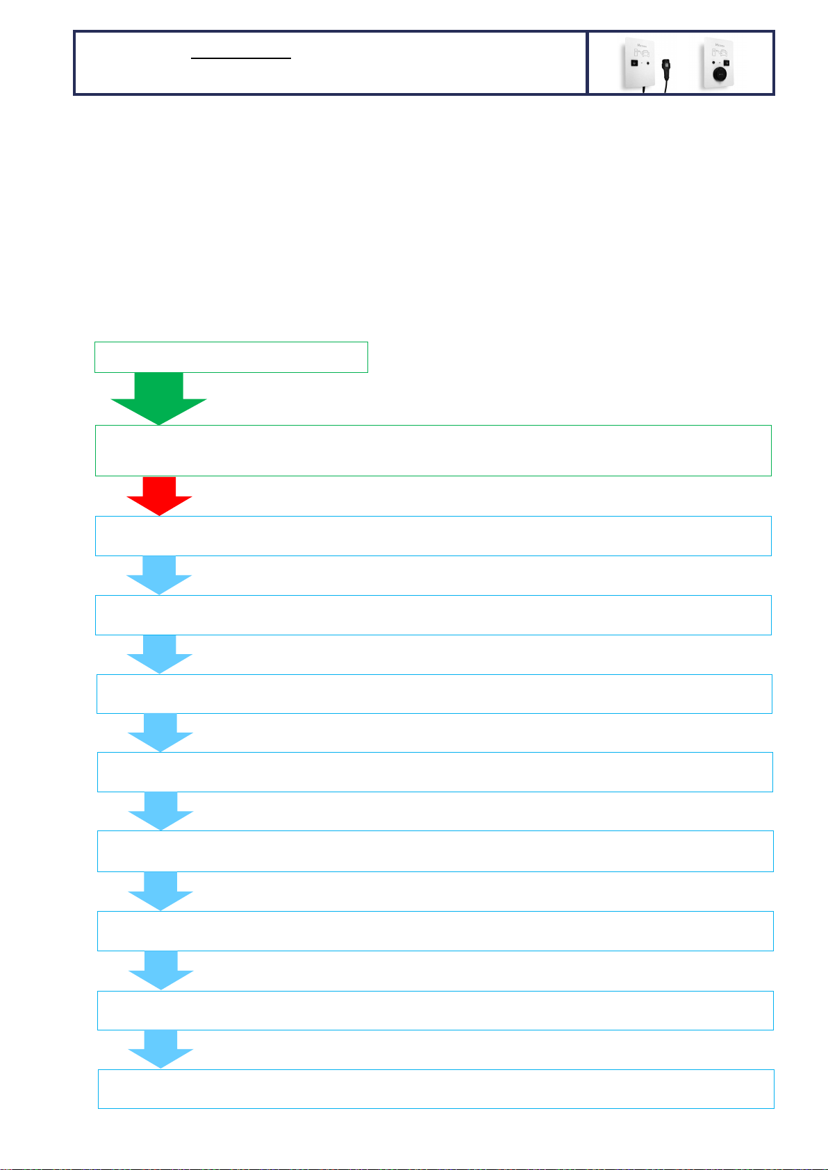
1. After installing the charging station as described on the Page 1 install the supplied current measuring
transformers (CT) on the house/building main power supply input and connect them to Micro EVSE 3
DYNAMIC WiFi EV charge controller as shown on the ME3-1 or/and ME3-2 drawings in the attachment.
2. Switch ON charging station power supply.
3. Set the needed parameters via front PUSH BUTTON: when no car is connected push the charging station front
button (blue status LED is switched OFF) and keep it pressed. After 5 seconds the status LED starts to blink.
The first set of blinks in this step is not important as this just limits/sets the user desired charging limit
(described on the first page). When the status LED stops blinking keep the button pressed for additional 30
seconds. After 30 seconds the blue status LED will start to blink again. Releasing the front push button after
certain LED blink sets the new value for desired parameter.
The following chart describes what can/shall be set:
Wait
5s
PRESS the BUTTON and keep it pressed
General NOTE: you can set only 1 parameter at a time. Setting
desired parameter does not have any influence on other
parameters. The set values stay saved in the memory
permanently (power loss doesn’t delete settings).
Wait
30s
5 or 8 LED blinks - Setting the charging current: 1 to 8 LED blinks represent 6A, 8A, 10A, 13A, 16A, 20A, 25A, 32A
charging current; 6,7,8 LED blinks exist only for 32A capable charging stations (1f/3f)
3 LED BLINKS - Solar/wind/hydro power plant phases: 1 to 3 LED blinks represent 1, 2 or 3 phase power plant grid connection.
Default setting: 3 phases
Wait
5s
Wait
5s
80 LED BLINKS - House main fuse rating: 1 to 80 LED blinks represent 1 to 80 A main fuse rating.
Default setting: 35 A
Wait
5s
5 LED BLINKS – Charging current regulation loop delay: 1 to 5 LED blinks represent 1 to 5 seconds charging current regulation
loop delay. Default setting: 2 seconds (shall not be changed!)
Wait
5s
2 LED BLINKS – ACTIVATION/ENABLE signal (RFID, RF remote, etc) or ACTIVATION via WiFi app. for charging start: 1 to 2 LED
blinks; 1 blink = activation not required, 2 blinks = activation required. Default setting: 1 = activation not required
Wait
5s
2 LED BLINKS – wireless main fuse protection dynamic charging RF receiver activation: 1 to 2 LED blinks; 1 blink = wireless OFF,
2 blinks = wireless ON. Default setting: 1 = wireless OFF
Wait
5s
25 LED BLINKS – Wireless RF receiver channel: 1 to 25 LED blinks that represent 1 to 25 RF channels.
Default setting: channel 1
3 LED BLINKS - House grid connection phases: 1 to 3 LED blinks represent 1, 2 or 3 phase grid connection.
Default setting: 3 phases
30 LED BLINKS – station ID (identification) that is used for optimized and prioritized wireless main fuse protection dynamic
charging
of more than 1 charging station:
1 to
30
LED blinks
that represent station’s IDs from
1
to 30
.
Default setting: 1
Wait
5s
HARDWIRED 1 or 3-phase MAIN FUSE protection DYNAMIC
charging with 1 WALL MOUNTED charging station per fuse

Page 4
4. Example: if you have 20 A main fuse and would like to change it in Micro EVSE 3, press a front button on keep
the button pressed….pass the 1st set of blinks, 2nd set of blinks, 3rd set of blinks and when you get to the 4th
set of blinks count the LED blinks to 20 and at 20th blink release the button. Now the station “knows” the
rating of main fuse (amperage). You can see what you set in the WiFi app. in “Advanced info” menu.
5. Test the 3/1-phase main fuse protection dynamic charging:
Connect to WiFi and go to the Metron Charge Control web-based application. Connect the electric vehicle to
the charging station and observe the charging current measurements in WiFI Charge Control app. under
“Advanced info”. Intentionally put the big load to each of the phases (one by one) to surpass the main fuse
rated current and observe if the charging current decreased in the way the total main fuse current is not
higher than main fuse rated current. To do that you need to connect powerful load to each phase (easiest
way is to use regular 2 kW electric heaters – 1,2,3… connected in parallel.
6. Explain to the client that the charging station will automatically reduce or stop the charging in case of main
fuse overload. In case of charging interruption because of overload the blue status LED will blink 4 times
(with pause after 4 blinks) until the load on the main fuse is low enough to resume charging. The main fuse
current on the most loaded phase needs to be app. 7A lower than rated fuse current in order the charging
station will allow charging to start/resume. The status LED can blink 4 times even if the vehicle is not
connected. This will inform the user that the charging cannot start until the other powerful house loads are
switched-off.
7. Explain to the client that in case of installed solar/wind/hydro power plant the charging station allows vehicle
charging with higher overall current than the set nominal main fuse value (this function doesn’t work at
night of course). This feature is active only in case Solar/wind/hydro power plant phases = House grid
connection phases.

Page 5
1. Install the charging station as described on the Page 1.
2. Switch ON charging station power supply.
3. Set the main fuse rating to 35A (needed only if it has been changed - factory default setting is already 35A)
via front PUSH BUTTON + status LED blinks as described on Page 3.
4. Activate main fuse protection dynamic charging RF receiver via front PUSH BUTTON + status LED blinks as
described on Page 3 (by default the RF receiver is not activated).
5. If necessary set the other parameters via front PUSH BUTTON + status LED blinks as described on Page 3.
6. Install and set the 3FD-2 DYNAMIC EV CHARGING UNIT as described on pages 7, 8 and 9.
WIRELESS 1 or 3-phase MAIN FUSE protection DYNAMIC
charging with 1 or more WALL MOUNTED charging stations

Page 6
1. Connect the portable charging station to wall socket (apply the power supply).
2. Set the needed parameters via front PUSH BUTTON: when no car is connected push the charging station front
button (blue status LED is switched OFF) and keep it pressed. After 5 seconds the status LED starts to blink.
The first set of blinks in this step is not important as this just limits/sets the user desired charging limit
(described on the first page). When the status LED stops blinking keep the button pressed for additional 30
seconds. After 30 seconds the blue status LED will start to blink again. Releasing the front push button after
certain LED blink sets the new value for desired parameter.
The following chart describes what can/shall be set:
3. Example: if you have wireless RF receiver set to channel 1 and would like to change it to channel 15, press a
front button on keep the button pressed….pass the 1st set of blinks, 2nd set of blinks, 3rd set of blinks, 4th set
of blinks, 5th set of blinks and when you get to the 6th set of blinks count the status LED blinks to 15 and at
15th blink release the button. Now the station’s RF receiver is set to 15th channel. You can see what you set in
the WiFi Charge Control app. in “Advanced info” menu.
4. Install and set the 3FD-2 DYNAMIC EV CHARGING UNIT as described on pages 7, 8 and 9.
Wait
5s
PRESS the BUTTON and keep it pressed
General NOTE: you can set only 1 parameter at a time. Setting
desired parameter does not have any influence on other
parameters. The set values stay saved in the memory
permanently (power loss doesn’t delete settings).
Wait
30s
5 or 8 LED blinks - Setting the charging current: 1 to 8 LED blinks represent 6A, 8A, 10A, 13A, 16A, 20A, 25A, 32A
charging current; 6,7,8 LED blinks exist only for 32A capable charging stations (1f/3f)
3 LED BLINKS - Solar/wind/hydro power plant phases: 1 to 3 LED blinks represent 1, 2 or 3 phase power plant grid connection.
Default setting: 3 phases
Wait
5s
Wait
5s
2 LED BLINKS – wireless main fuse protection dynamic charging RF receiver activation: 1 to 2 LED blinks; 1 blink = wireless OFF,
2 blinks = wireless ON. Default setting: 2 = wireless ON
Wait
5s
25 LED BLINKS – Wireless RF receiver channel: 1 to 25 LED blinks that represent 1 to 25 RF channels.
Default setting: channel 1
3 LED BLINKS - House grid connection phases: 1 to 3 LED blinks represent 1, 2 or 3 phase grid connection.
Default setting: 3 phases
30 LED BLINKS – station ID (identification) that is used for optimized and prioritized wireless main fuse protection dynamic
charging
of more than 1 charging station:
1 to
30
LED blinks
that represent station’s IDs from
1
to 30
.
Default setting: 1
Wait
5s
WIRELESS 1 or 3-phase MAIN FUSE protection DYNAMIC
charging with 1 or more PORTABLE charging stations

Page 7
1. Activate wireless FUSE protection DYNAMIC charging on wall mounted station(s) (default setting is
“wireless off”) as described on Page 3 (portable stations have enabled wireless dynamic charging RF receiver
by default). You also need to set house phases and solar phases but don’t change the main fuse rating on
the wall mounted station (leave default 35 A or set in back to 35A if it has been changed).
2. Install the 3FD-2 DYNAMIC EV CHARGING UNIT and supplied current measuring transformers (CT) on the
house/building main power supply input (in the house main distribution panel) as shown on the 3FD-2-4
or/and 3FD-2-5 drawings in the attachment.
3. Open the top cover of the installed 3FD-2 DYNAMIC EV CHARGING UNIT and set the needed parameters via
PB2 PUSH BUTTON you can find on the 3FD-2 printed circuit board: press the PB2 (red LED is switched OFF)
and keep it pressed. After 3 seconds the red LED starts to blink. Releasing the PB2 push button after certain
red LED blink sets the new value for desired parameter.
The following chart describes what can/shall be set:
Wait
3s
PRESS the PB2 button and keep it
pressed
General NOTE: you can set only 1 parameter at a time. Setting
desired parameter does not have any influence on other
parameters. The set values stay saved in the memory
permanently (power loss doesn’t delete settings).
Wait
5s
30 red LED BLINKS
–
number of controlled charging stations
: 1 to 30 LED blinks represent 1 to 30
charging stations. Default setting: 1 charging station
3 red LED BLINKS
-
Solar/wind/hydro power plant
phases
: 1 to 3 LED blinks represent 1, 2 or 3 phase
power plant grid connection. Default setting: 3 phases
Wait
5s
3 red LED BLINKS
-
House grid connection phases
: 1 to 3 LED blinks represent 1, 2 or 3 phase grid
connection. Default setting: 3 phases
Wait
5s
3 red LED BLINKS
-
Current measuring range
: 1 to 3 LED blinks represent:
- 1 blink = measuring range from 1A to 80A (no further actions, use supplied CTs)
- 2 blinks = measuring range from 1A to 160A (connect 1 additional 84.5 Ohm resistor between
each current measuring input and GND; any CTs with at least 160 A rated current and current
ratio 2000/1 can be used)
- 3 blinks = measuring range from 1A to 250A (connect 2 additional 84.5 Ohm resistors between
each current measuring input and GND; any CTs with at least 250 A rated current and current
ratio 2000/1 can be used)
Default setting: 1
Wait
5s
32 red LED BLINKS
-
MASTER charging current limit:
1 to 32 LED blinks that represent maximum charging
current (from 1A to 32A) that will be allowed by the 3FD-2 module no matter what charging current
settings are set on the individual wirelessly controlled charging station. Default setting: 32 A
Wait
5s
250 red LED BLINKS
-
House main fuse rating
: 1 to 250 LED blinks represent 1 to 250
A main fuse rating.
Default setting: 35 A
INSTALLING the 3FD-2 DYNAMIC EV CHARGING UNIT for 1 or 3-
phase MAIN FUSE protection WIRELESS DYNAMIC charging of up
to
30
wall mounted and portable charging stations per main fuse

Page 8
4. Example: if you have 63 A main fuse and would like to change it, press the PB2 button on keep the button
pressed….pass the 1st set of blinks, 2nd set of blinks, 3rd set of blinks, 4th set of blinks, 5th set of blinks and
when you get to the 6th set of blinks count the red LED blinks to 63 and at 63th blink release the button. Now
the 3FD-2 module “knows” the rating of main fuse (amperage). You can see what you set in the WiFi Charge
Control app. in “Advanced info” menu on any one of the wirelessly controlled charging stations.
5. In case there are more than 1 WALL MOUNTED AND/OR PORTABLE station(s) to be controlled by the 3FD-2
DYNAMIC EV CHARGING UNIT set the number of charging stations with BP2 and red LED blinks as described
on Page 7. At the same time you need to set the parameter station ID for each wall mounted or wireless
charging station (see Page 5 and 6) in the way each charging station has its own ID starting from 1. Example:
you have 3 charging stations connected to the same main fuse; set the ID on first one to 1, second one to 2
and on the third one to 3. The station ID is displayed in the WiFi Charge Control app. in “Advanced info”
menu. The DYNAMIC fuse protection charging works also in case you have a MIXED configuration - 1 or
more wall mounted and 1 or more portable stations powered from the same main fuse!
6. Test the 3/1-phase wireless main fuse protection dynamic charging: Connect to WiFi and go to the Metron
Charge Control application on one of the wirelessly controlled charging stations. Connect the electric vehicle
to the charging station and observe the charging current measurements in WiFI Charge Control app. under
“Advanced info”. Intentionally put the big load to each of the phases (one by one) to surpass the main fuse
rated current and observe if the charging current decreased in the way the total main fuse current is not
higher than main fuse rated current. To do that you need to connect powerful load to each phase (easiest
way is to use regular 2 kW electric heaters – 1,2,3… connected in parallel). Red LED inside the 3FD-2 box is
blinking in normal conditions and is constantly ON in overload condition. Green LED inside the 3FD-2 box is
blinking only when there is some solar/wind/hydro production otherwise it’s off.
7. Changing the transmitter/receiver channel: In case of interference with other 433 MHz devices you need to
change communication channel on the transmitting 3FD-2 unit and receiving charging station/s. There are 25
different channels (frequencies) available. First open the top cover of the installed 3FD-2 DYNAMIC EV
CHARGING UNIT and you will see Blue LED blinking every 3 seconds what indicates wireless signal
transmission. Then press the button PB1 (blue LED turns off) and keep it pressed. After 3 seconds the blue
LED starts to blink. Releasing the PB1 push button after certain blue LED blink set the new transmitting
channel.
The following chart describes how to change transmitter channel on 3FD-2 unit:
Then turn off the power supply of the 3FD-2 unit (very important!) and after that set the same channel on
one or more wall mounted and/or portable charging stations as described on Pages 5 and 6.
NOTE: if there is no signal from the 3FD-2 unit detected on the charging station side (you can see that
information in the WiFi Metron Charge Control application under “Advanced info”) the wall mounted
charging station will stop charging and the front blue status LED will blink 4 times as in case of main fuse
overload condition but the portable charging station will continue charging with user selected charging
current/power – this function is logical for portable stations because when you charge somewhere else
where 3FD-2 unit is not present its purpose is to charge.
Communication signal detection on wall mounted stations can also be observed if LED2 is connected
between terminal 20 and GND on the Micro EVSE 3 DYNAMIC WiFi EV charge controller in the charging
station (signal present = LED2 on; no signal = LED2 off). Portable stations have SIGNAL LED already installed.
Wait
3s
PRESS the PB
1
button and keep it pressed
25
blue
LED BLINKS
–
Wireless RF
transmitter
channel
: 1 to 25 LED blinks that represent 1 to 25
RF
channels. Default setting: channel 1

Page 9
8. Extending the wireless range of 3FD-2 DYNAMIC EV CHARGING UNIT: in case the 3FD-2 and controlled
stations are far away from each other (50m+ air distance) or there are thick concrete walls in between the
signal may be too weak. But there are 2 ways of extending the wireless range:
- Install additional 433 MHz antenna on a station(s). Antenna shall be installed on the outside wall and
connected with attached cable to the Micro EVSE 3 DYNAMIC WiFi EV charge controller. Use pliers and
cut-off the built-in antenna. This is the most affective way to extend signal range. Note: It is not possible
to install additional antenna on portable stations.
- Install additional 433 MHz antenna on 3FD-2 DYNAMIC EV CHARGING UNIT. Use pliers and cut-off the
built-in antenna. This antenna also helps extend the range but it’s less effective.
9. Explain to the client that 3FD-2 DYNAMIC EV CHARGING UNIT distributes the charging power to all
wirelessly controlled charging stations equally. However, the client can still adjust the charging power on
each station via front button or via current setting slider in WiFi Metron Charge Control application.
10. Explain to the client that in case of wirelessly controlling only one (1) charging station it will automatically
reduce charging power or stop the charging in case of main fuse overload. In case of charging interruption
because of overload the station’s front blue status LED will blink 4 times (with pause after 4 blinks) until
the load on the main fuse is low enough to resume charging. The main fuse current on the most loaded
phase needs to be app. 7A lower than rated fuse current in order the 3FD-2 will allow charging to
start/resume. The blue front status LED can blink 4 times even if the vehicle is not connected. This informs
the user in advance that charging cannot start until the other powerful house loads are switched-off.
11. Explain to the client that in case of wirelessly controlling two (2) or more charging stations it will
automatically reduce the charging power on all the stations in case of main fuse overload. If that is not
enough it will stop charging on one or more charging stations starting with the one with highest station ID
number. In case of charging interruption because of overload the affected station’s front blue status LED
will blink 4 times (with pause after 4 blinks) until the load on the main fuse is low enough to resume
charging. If the main fuse is too overloaded by other loads it will stop charging on all the stations. After the
load on main fuse is reduced the charging will be resumed starting on the stations with lower station ID
numbers (lower station’s ID numbers have the priority over the higher station’s ID numbers). The main fuse
current on the most loaded phase needs to be app. n x 7A lower (n = number of stations that will be allowed
to resume charging) than rated fuse current in order the 3FD-2 will allow charging to start/resume on the
additional n charging stations. The blue front status LED on one or more stations can blink 4 times even if the
vehicle(s) is(are) not connected. This informs the user in advance that charging cannot start until the other
powerful house loads are switched-off.
12. Explain to the client that in case of installed solar/wind/hydro power plant the 3FD-2 DYNAMIC EV
CHARGING UNIT allows vehicle charging with higher overall current than the set nominal main fuse value
(this function doesn’t work at night of course). This feature is active only in case Solar/wind/hydro power
plant phases = House grid connection phases.
13. Explain to the client that in case of using the a PORTABLE CHARGING STATION PC03X+ / PC04X+ / PC05X+ on
2 or more different places (e.g. the client has 2 houses) it is possible to install the 3FD-2 DYNAMIC EV
CHARGING UNITs on 2 or more different locations (e.g. 2 houses) with different main fuses and then just
move/use the same PORTABLE CHARGING STATION on those different locations and have everywhere safe
wireless FUSE protection DYNAMIC charging. The PORTABLE CHARGING STATION connects automatically
to 3FD-2 DYNAMIC EV CHARGING UNIT at every location.

Page 10
ATTACHMENTS
Mark Type Description Revison
ME3
-
1
D
rawing
3
-
phase
MAIN
FUSE protection DYNAMIC charging with 1
wall mounted
charging station per main fuse – HARDWIRED option
2
ME3
-
2
D
rawing
1
-
phase MAIN FUSE protection DYNAMIC charging with 1
wall mounted
charging station per main fuse – HARDWIRED option
2
3FD
-
2
-
4
D
rawing
3
-
phase
MAIN FUSE protection DYNAMIC charging with
1 or more wall
mounted or portable charging stations per main fuse – WIRELESS option
2
3FD
-
2
-
5
D
rawing
1
-
phase
MAIN FUSE protection DYNAMIC charging with
1 or more wall
mounted or portable charging stations per main fuse – WIRELESS option
2
HOUSE MAIN
DISTRIBUTION PANEL
L1 L2 L3 N
Drawing: ME3-1
Date: 16.11.2022
Revision: 2Author: D. Skrivalnik
CTL1
CT solar
CTL2
CTL3
GRID TIE
PV inverter
S1 - switch for activating/deactivating
solar SURPLUS electric vehicle charging
(S1 closed = solar SURPLUS charging)
S1 mounting location: anywhere
NOTE: Solar SURPLUS charging can also
be activated via WiFi Metron Charge Control app.
S1
CHARGING STATION
3f GRID 400V/50Hz
L1
L1 L1
L2
L2 L2
L3
L3 L3
N
NN
MAIN FUSES
ENERGY
COUNTER
kWh
CAT6 Ethernet cable
Nin
Lin
90-270V
RELAY
PE/GND
LOCK
SOL.ch.
Count
CMIsol
CMI1
CMI2
CMI3
GND
EV CHARGE CONTROLLER
MODEL: Micro EVSE 3 DYNAMIC WiFi HW
R
Ch:
www.eauto.si
CP
PP
PB
LED1
LED2
0-5V
Enable
+12V
CT1
CT2
CT3
GND
10 11 12
24 23 22 21 20 19 18 17 16 15 14 13
123456789
INSTALATION OF METRON Micro EVSE 3 DYNAMIC WiFi
based WALL MOUNTED CHARGING STATION
for 3-phase DYNAMIC MAIN FUSE PROTECTION
CHARGING of electric vehicleONE (1)
HARDWIRED OPTION
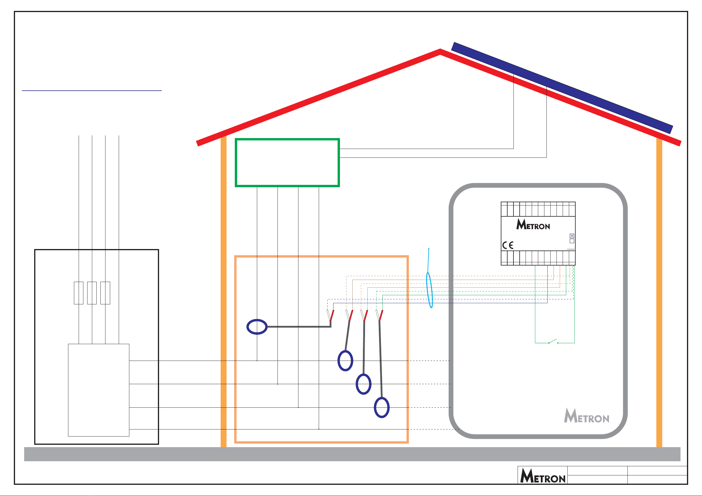
HOUSE MAIN
DISTRIBUTION PANEL
L1 N
Drawing: ME3-2 Date: 16.11.2022
Revision: 2Author: D. Skrivalnik
CTL1
CT solar
GRID TIE
PV inverter
S1 - switch for activating/deactivating
solar SURPLUS electric vehicle charging
(S1 closed = solar SURPLUS charging)
S1 mounting location: anywhere
NOTE: Solar SURPLUS charging can also
be activated via WiFi Metron Charge Control app.
S1
CHARGING STATION
1f GRID 230V/50Hz
L1
L1 L1
N
NN
MAIN FUSE
ENERGY
COUNTER
kWh
CAT6 Ethernet cable
INSTALATION OF METRON Micro EVSE 3 DYNAMIC WiFi
based WALL MOUNTED CHARGING STATION
for 1-phase DYNAMIC MAIN FUSE PROTECTION
CHARGING of electric vehicleONE (1)
HARDWIRED OPTION
Nin
Lin
90-270V
RELAY
PE/GND
LOCK
SOL.ch.
Count
CMIsol
CMI1
CMI2
CMI3
GND
EV CHARGE CONTROLLER
MODEL: Micro EVSE 3 DYNAMIC WiFi HW
R
Ch:
www.eauto.si
CP
PP
PB
LED1
LED2
0-5V
Enable
+12V
CT1
CT2
CT3
GND
10 11 12
24 23 22 21 20 19 18 17 16 15 14 13
123456789

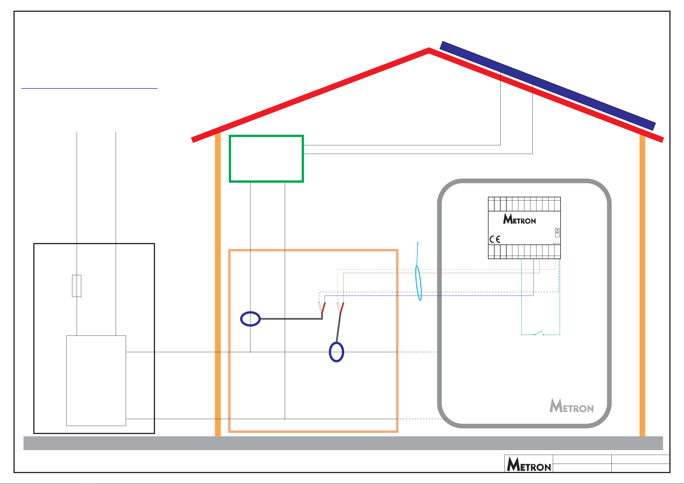
HOUSE MAIN
DISTRIBUTION PANEL
Station ID: 1
Station ID: 4
Station ID: 2
L1 L2 L3 N
Drawing: 3FD-2-4 Date: 16.11.2022
Revision: 2Author: D. Skrivalnik
CTL1
CT solar
CTL2
CTL3
GRID TIE
PV inverter
S1 - switch for activating/deactivating
solar SURPLUS electric vehicle charging
(S1 closed = solar SURPLUS charging)
S1 mounting location: anywhere
NOTE: Solar SURPLUS charging can also
be activated via WiFi Metron Charge Control app.
S1 - switch for activating/deactivating
solar SURPLUS electric vehicle charging
(S1 closed = solar SURPLUS charging)
S1 mounting location: anywhere
NOTE: Solar SURPLUS charging can also
be activated via WiFi Metron Charge Control app.
S1
S1
CHARGING STATION 1
CHARGING STATION 2
CHARGING STATION 4
CHARGING STATION 3
3f GRID 400V/50Hz
L1
L1 L1
L2
L2 L2
L3
L3 L3
N
NN
MAIN FUSES
ENERGY
COUNTER
kWh
Nin Nin
Lin
90-270V
Lin
90-270V
RELAY RELAY
PE/GND PE/GND
LOCK LOCK
SOL.ch. SOL.ch.
Count Count
CMIsol CMIsol
CMI1 CMI1
CMI2 CMI2
CMI3 CMI3
GND GND
EV CHARGE CONTROLLER
MODEL: Micro EVSE 3 DYNAMIC WiFi
EV CHARGE CONTROLLER
MODEL: Micro EVSE 3 DYNAMIC WiFi
HW
HW
R
R
Ch:
Ch:
www.eauto.si
www.eauto.si
CP
CP
PP
PP
PB
PB
LED1
LED1
LED2
LED2
0-5V
0-5V
Enable
Enable
+12V
+12V
CT1
CT1
CT2
CT2
CT3
CT3
GND
GND
10
10
11
11
12
12
24
24
23
23
22
22
21
21
20
20
19
19
18
18
17
17
16
16
15
15
14
14
13
13
1
1
2
2
3
3
4
4
5
5
6
6
7
7
8
8
9
9
L1in
L2in
L3in
Nin
GND
CTL1
GND
CTL2
GND
CTL3
GND
CTSOLAR
DYNAMIC EV ING UNITCHARG
MODEL: 3FD-2
T
Ch: 12
12
12
www.eauto.si
TX2
RX2
RX1
TX1
0-5V 2
0-5V 1
AI2
AI1
DI3
DI2
DI1
GND
10 11 12
24 23 22 21 20 19 18 17 16 15 14 13
123456 789
INSTALATION OF 3FD-2 DYNAMIC EV CHARGING UNIT, Micro
EVSE 3 DYNAMIC WiFi based WALL MOUNTED stations
and Micro EVSE 4 based PORTABLE stations for
3-phase DYNAMIC MAIN FUSE PROTECTION
CHARGING of electric vehiclesONE or MORE
WIRELESS OPTION
Ch:
Ch:
12
12
Station ID: 3
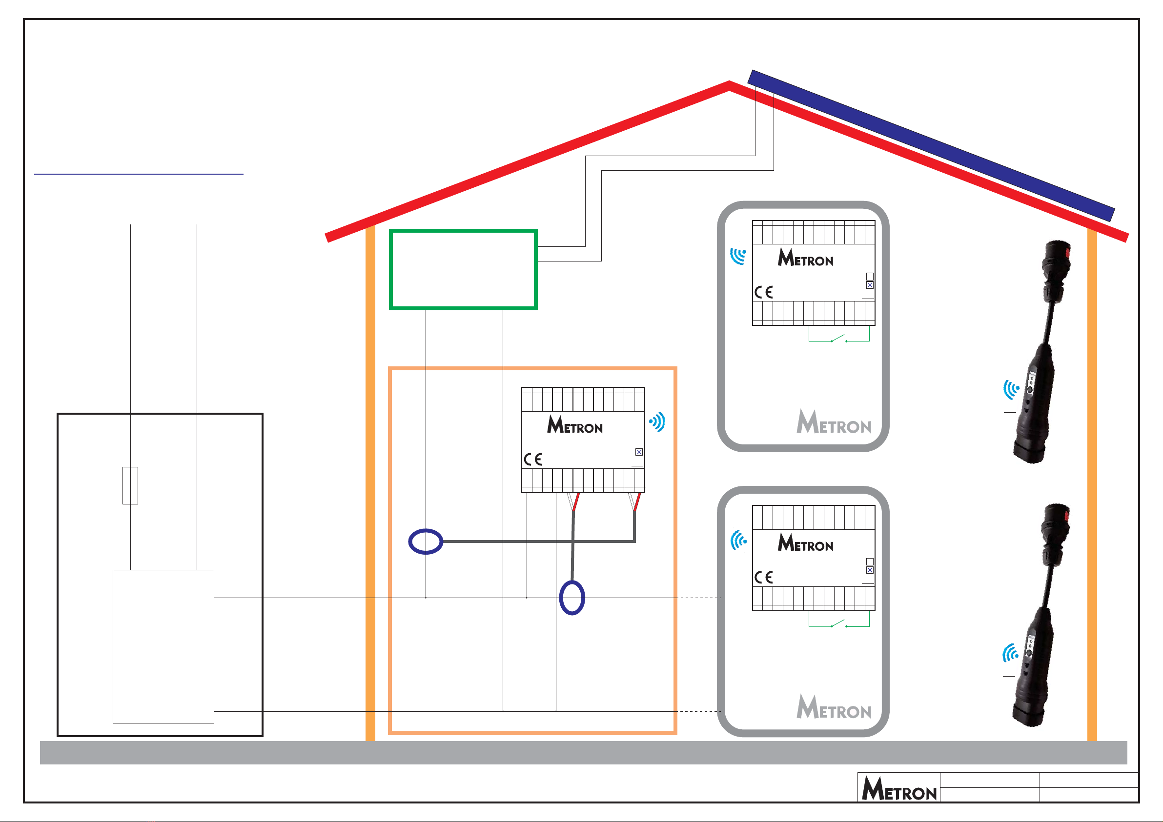
HOUSE MAIN
DISTRIBUTION PANEL
Station ID: 1
Station ID: 4
Station ID: 2
L1 N
Drawing: 3FD-2-5 Date: 16.11.2022
Revision: 2Author: D. Skrivalnik
CTL1
CT solar
GRID TIE
PV inverter
S1 - switch for activating/deactivating
solar SURPLUS electric vehicle charging
(S1 closed = solar SURPLUS charging)
S1 mounting location: anywhere
NOTE: Solar SURPLUS charging can also
be activated via WiFi Metron Charge Control app.
S1 - switch for activating/deactivating
solar SURPLUS electric vehicle charging
(S1 closed = solar SURPLUS charging)
S1 mounting location: anywhere
NOTE: Solar SURPLUS charging can also
be activated via WiFi Metron Charge Control app.
S1
S1
CHARGING STATION 1
CHARGING STATION 2
CHARGING STATION 4
CHARGING STATION 3
1f GRID 230V/50Hz
L1
L1 L1
N
NN
MAIN FUSE
ENERGY
COUNTER
kWh
Nin Nin
Lin
90-270V
Lin
90-270V
RELAY RELAY
PE/GND PE/GND
LOCK LOCK
SOL.ch. SOL.ch.
Count Count
CMIsol CMIsol
CMI1 CMI1
CMI2 CMI2
CMI3 CMI3
GND GND
EV CHARGE CONTROLLER
MODEL: Micro EVSE 3 DYNAMIC WiFi
EV CHARGE CONTROLLER
MODEL: Micro EVSE 3 DYNAMIC WiFi
HW
HW
R
R
Ch:
Ch:
www.eauto.si
www.eauto.si
CP
CP
PP
PP
PB
PB
LED1
LED1
LED2
LED2
0-5V
0-5V
Enable
Enable
+12V
+12V
CT1
CT1
CT2
CT2
CT3
CT3
GND
GND
10
10
11
11
12
12
24
24
23
23
22
22
21
21
20
20
19
19
18
18
17
17
16
16
15
15
14
14
13
13
1
1
2
2
3
3
4
4
5
5
6
6
7
7
8
8
9
9
L1in
L2in
L3in
Nin
GND
CTL1
GND
CTL2
GND
CTL3
GND
CTSOLAR
DYNAMIC EV ING UNITCHARG
MODEL: 3FD-2
T
Ch: 12
12
12
www.eauto.si
TX2
RX2
RX1
TX1
0-5V 2
0-5V 1
AI2
AI1
DI3
DI2
DI1
GND
10 11 12
24 23 22 21 20 19 18 17 16 15 14 13
123456 789
INSTALATION OF 3FD-2 DYNAMIC EV CHARGING UNIT, Micro
EVSE 3 DYNAMIC WiFi based WALL MOUNTED stations
and Micro EVSE 4 based PORTABLE stations for
1-phase DYNAMIC MAIN FUSE PROTECTION
CHARGING of electric vehiclesONE or MORE
WIRELESS OPTION
Ch:
Ch:
12
12
Station ID: 3
Other manuals for Nano(+)
1
This manual suits for next models
6
Table of contents
Other METRON Batteries Charger manuals
 User manual")


 User manual")


