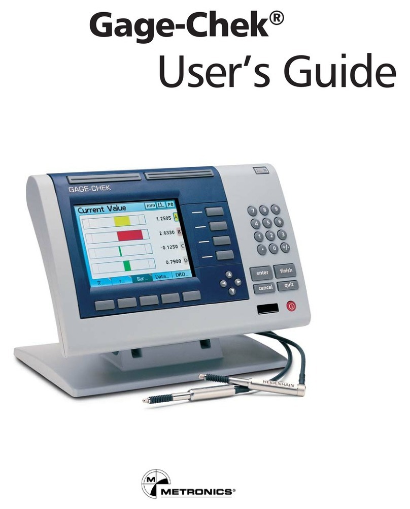
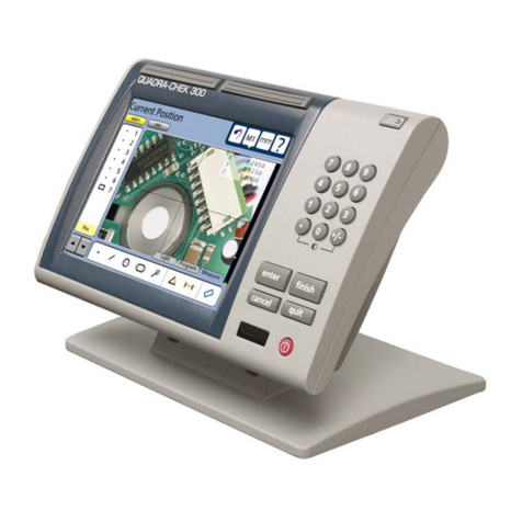
Metronics Quadra-Chek 200 User manual

Quadra-Chek® 200
User’s Guide


Metronics, Inc.
Bedford, New Hampshire, USA
Quadra-Chek® 200
User’s Guide

Proprietary Notice
All information set forth in this document, all rights to such information, any
and all inventions disclosed herein and any patents that might be granted by
employing the materials, methods, techniques or apparatus described herein are
the exclusive property of Metronics Incorporated, Bedford, New Hampshire.
No part of this document may be reproduced, stored in a retrieval system, or
transmitted in any form or by any means, electronic, mechanical, photocopying,
recording, or otherwise, without the prior permission of Metronics Incorporated.
The information contained herein is designed only for use with the Quadra-
Chek 200 Digital Readout. Metronics Incorporated is not responsible for any
use of this information as applied to any other apparatus.
Disclaimer
The information contained in this document is subject to change without no-
tice. Metronics Incorporated assumes no responsibility or liability for any errors
or inaccuracies contained herein, or for incidental or consequential damage in
connection with the furnishing, performance, or use of this guide.
Metronics Inc. shall not be liable to the purchaser of this product or third parties
for damages, losses, costs, or expenses incurred by the purchaser or third parties
as a result of: accident, misuse, or abuse of this product or unauthorized modifi-
cations, repairs, or alterations to this product, or failure to strictly comply with
Metronics Incorporated’s operating and maintenance instructions.
Trademarks
Metronics, Quadra-Chek, Quadra-Chek 200, and QC200 are registered trade-
marks of Metronics Incorporated.
Other product names used herein are for identification purposes only and may
be trademarks of their respective owners. Metronics Incorporated disclaims any
and all rights to those marks.
Safety & Mai te a ce
Co sideratio s
General safety precautions must be followed when operating the system. Failure
to observe these precautions could result in damage to the equipment, or injury
to personnel. It is understood that safety rules within individual companies vary.
If a conflict exists between the material contained in this guide and the rules of a
company using this system, the more stringent rules should take precedence.
Although Metronics strongly recommends that you read all parts of this guide, it
is essential for reliable and safe operation to read the first portions up to and
including Chapter 3: Operation, prior to operating the QC200.

Locatio & Mou ti g
The QC200 must be placed or mounted on a stable, reliable surface. If the
QC200 should fall, it could become seriously damaged and more importantly
could cause injuries to the user. For mounting instructions, refer to the Getting
Started section of Chapter 3: Operation, for the mounting bolt hole pattern.
Clea i g
Use only a cloth dampened with water and a mild detergent for cleaning the
exterior surfaces. Never use abrasive cleaners, and never use strong detergents or
solvents. Only dampen the cloth, do not use a cleaning cloth that is dripping
wet.
Electrical
Do not allow the power cord to be located such that it can be walked on or create
a tripping hazard.
WARNINGWARNING
WARNINGWARNING
WARNING
Unplug the QC200 from the electrical outlet before cleaningUnplug the QC200 from the electrical outlet before cleaning
Unplug the QC200 from the electrical outlet before cleaningUnplug the QC200 from the electrical outlet before cleaning
Unplug the QC200 from the electrical outlet before cleaning
WARNINGWARNING
WARNINGWARNING
WARNING
The QC200 is equipped with a 3-wire power plug that includesThe QC200 is equipped with a 3-wire power plug that includes
The QC200 is equipped with a 3-wire power plug that includesThe QC200 is equipped with a 3-wire power plug that includes
The QC200 is equipped with a 3-wire power plug that includes
a separate ground connection Always connect the power pluga separate ground connection Always connect the power plug
a separate ground connection Always connect the power pluga separate ground connection Always connect the power plug
a separate ground connection Always connect the power plug
to a 3-wire grounded outlet The use of 2-wire power plugto a 3-wire grounded outlet The use of 2-wire power plug
to a 3-wire grounded outlet The use of 2-wire power plugto a 3-wire grounded outlet The use of 2-wire power plug
to a 3-wire grounded outlet The use of 2-wire power plug
adapters or any other connection accessories that remove theadapters or any other connection accessories that remove the
adapters or any other connection accessories that remove theadapters or any other connection accessories that remove the
adapters or any other connection accessories that remove the
third grounded connection create a safety hazard and shouldthird grounded connection create a safety hazard and should
third grounded connection create a safety hazard and shouldthird grounded connection create a safety hazard and should
third grounded connection create a safety hazard and should
not be permitted If a 3-wire grounded outlet is not available,not be permitted If a 3-wire grounded outlet is not available,
not be permitted If a 3-wire grounded outlet is not available,not be permitted If a 3-wire grounded outlet is not available,
not be permitted If a 3-wire grounded outlet is not available,
ask your electrician to provide oneask your electrician to provide one
ask your electrician to provide oneask your electrician to provide one
ask your electrician to provide one
Ge eral Mai te a ce
Unplug the QC200 from the wall outlet and seek the assistance of a qualified
service technician if:
•The power cord is frayed or damaged or the power plug is damaged
•Liquid is spilled or splashed onto the enclosure
•The QC200 has been dropped or the exterior has been damaged
•The QC200 exhibits degraded performance or indicates a need for ser
vice some other way

Backup Battery
Chargi g
The QC200 utilizes an internal battery to maintain system configuration set-
tings during power interruptions. A battery circuit charges this backup battery
during periods of normal operation.
When the QC200 is used on a daily basis, the backup battery will be adequately
charged to maintain configuration settings during power outages. However,
over extended periods of nonuse, the battery might lose the charge necessary to
maintain configuration settings. To keep the backup battery charged over ex-
tended periods of nonuse, apply power to the QC200 and leave it turned on for
a minimum of 2 days each month.

FCC Complia ce
Stateme t
FCC Rule NP15R Rev. 23, June, 1989
This equipment has been tested and found to comply with the limits for a Class
A digital device, pursuant to Part 15 of the FCC Rules. These limits are designed
to provide reasonable protection against harmful interference when the equip-
ment is operated in a commercial environment. This equipment generates, uses,
and can radiate radio frequency energy and, if not installed and used in accor-
dance with the instructions in this guide, may cause harmful interference to
radio communication. Operation of this equipment in a residential area is likely
to cause harmful interference, in which case the user will be required to correct
the interference at his own expense.
Shielded cables must be used with this unit to ensure compliance with Class A
FCC limits. The connection of a nonshielded equipment interface cable to this
equipment will invalidate the FCC Certification of this device and may cause
interference levels which exceed the limits established by the FCC for this equip-
ment. It is the responsibility of the user to obtain and use a shielded equipment
interface cable with this device. Do not leave cables connected to unused inter-
faces. Changes or modifications not expressly approved by the manufacturer
could void the user’s authority to operate the equipment.
For Canadian Users:
This Class “A” digital apparatus meets all requirements of the Canadian Interfer-
ence-Causing Equipment Regulations.
Cet appareil numérique de la classe “A” respecte toutes les exigences du Reglement
sur le matériel brouilleur du Canada.

Guide Part Number: 11A10487
Printing History:
April, 2000 First Printing Revision 1.0
June, 2000 Second Printing Revision 2.0
November, 2001 Third Printing Revision 3.0
Software Version: 1.23
Printed in the USA

I troductio
About this Guide
The material in this guide is divided into eight chapters. Topics range from basic
operating instructions to programming and system configuration. Chapters 1
through 3 contain the essential information to use the QC200. Do not operate
the QC200 unless the material in these chapters is thoroughly understood.
Keep this guide in a convenient location. Refer to it any time additional informa-
tion about the use and operation of the QC200 is needed. Use the index to
locate information by subject. Additional information related to this guide can
be found on the Internet at www.metronics.com/help.html.
Who Should Read
This Guide
This guide is intended for operators, technicians, supervisors, and dealer repre-
sentatives.
NOTENOTE
NOTENOTE
NOTE
System setup and configuration instructions provided in chapterSystem setup and configuration instructions provided in chapter
System setup and configuration instructions provided in chapterSystem setup and configuration instructions provided in chapter
System setup and configuration instructions provided in chapter
7 are intended for qualified supervisors, dealer representatives7 are intended for qualified supervisors, dealer representatives
7 are intended for qualified supervisors, dealer representatives7 are intended for qualified supervisors, dealer representatives
7 are intended for qualified supervisors, dealer representatives
and OEMs onlyand OEMs only
and OEMs onlyand OEMs only
and OEMs only Operators should not attempt to alter the Operators should not attempt to alter the
Operators should not attempt to alter the Operators should not attempt to alter the
Operators should not attempt to alter the
configuration of the QC200configuration of the QC200
configuration of the QC200configuration of the QC200
configuration of the QC200
What This Guide
Covers
Chapter 1: Overview
This chapter describes the use and application of the QC200 digital readout and
includes an annotated drawing and technical specifications.
Chapter 2: Quick-start
Use this chapter as a basic user tutorial. The quick start demonstration provides
QC200 operation instructions with a minimum of details.
Chapter 3: Operation
This chapter includes detailed descriptions of controls and indicators, and in-
structions for measuring, constructing, creating, and tolerancing features.

Chapter 4: Programming
This chapter contains instructions for recording, running, and editing QC200
programs.
Chapter 5: Edge detectors
Information in this chapter provides background and reference material regard-
ing edge detector installation and operation.
Chapter 6: Communications
Use this chapter to connect the QC200 to a printer or computer via the RS-232
or parallel port.
Chapter 7: Setup
This chapter contains system configuration instructions for qualified supervisors
and dealer representatives.
Chapter 8: Reference
This chapter contains additional information about quantization error, best fit
algorithms, and repeatability.
Co ve tio s & Terms
The terms Quadra-Chek 200, QC200 in this guide refer to the Quadra-Chek
200 digital readout. System refers to the QC200 and the measuring device
connected to it.
Comparator refers to any device intended to measure parts in 2 dimensions.
Crosshairs and edge detector refer to the probing method of the connected measur-
ing device. Probing refers to the process of measuring a point on a feature.
A program is simply a series of key-presses used to perform measurements and
stored by the system for later use.

Ico s
This guide uses the following icons to highlight information:
War i g
The raised hand icon warns of a situation or condition that can lead to personal
injury or death. Do not proceed until the warning is read and thoroughly
understood. Warning messages are shown in bold type.
Cautio
The exclamation point icon indicates a situation or condition that can lead to
equipment malfunction or damage. Do not proceed until the caution message is
read and thoroughly understood. Caution messages are shown in bold type.
Note
The note icon indicates additional or supplementary information about an activ-
ity or concept. Notes are shown in bold type.
Type Styles Warnings, cautions, and notes are shown in this typefaceWarnings, cautions, and notes are shown in this typeface
Warnings, cautions, and notes are shown in this typefaceWarnings, cautions, and notes are shown in this typeface
Warnings, cautions, and notes are shown in this typeface
Italics indicate menu items, front panel keys, input fields, or soft keys.

Measureme t Polarity
Instructions in this guide assume that:
•Moving crosshairs to the right causes the X axis counts to increase in a
positive direction; 1 to 2 to 3 and so on.
•Moving crosshairs up causes the Y axis counts to increase in a positive
direction; 1 to 2 to 3 and so on.
•Rotating crosshairs counterclockwise causes the Q axis counts to increase
in a positive direction; 1 degree to 2 degrees to 3 degrees and so on.
•To reverse the count direction of any axis, see the encoders section of
chapter7: setup.
Display Resolutio
i this Guide
Generally, the display resolution shown in this guide is one ten-thousandth of an
inch (0.0001in) or two microns (0.002mm). Display resolutions in this guide
are examples only. User display resolutions are likely to vary according to the
specific application.
Accuracy & Precisio
Measurement accuracy is determined by the resolution of the encoders on the
measuring device. Generally, the display resolution of the QC200 can exceed
the encoder resolution. Setting the display resolution to exceed the encoder
resolution does not increase measurement accuracy. See chapter 7: setup for more
information.
System Co figuratio
& Setup
All system setup and configuration must be performed by an authorized
Metronics distributor or OEM. Setup includes calibration with the measuring
device and configuration of non-linear error compensation (NLEC) if needed.
Anytime the QC200 is connected to a different measuring device, it is necessary
to perform configuration and setup again. Qualified supervisory personnel
should refer to chapter 7: setup or contact their Metronics distributor for assis-
tance.
WARNINGWARNING
WARNINGWARNING
WARNING
Electrical shock risk: do not open the QC200 enclosure ThereElectrical shock risk: do not open the QC200 enclosure There
Electrical shock risk: do not open the QC200 enclosure ThereElectrical shock risk: do not open the QC200 enclosure There
Electrical shock risk: do not open the QC200 enclosure There
are no user-serviceable components or assemblies inside Contactare no user-serviceable components or assemblies inside Contact
are no user-serviceable components or assemblies inside Contactare no user-serviceable components or assemblies inside Contact
are no user-serviceable components or assemblies inside Contact
your Metronics distributor for service and maintenanceyour Metronics distributor for service and maintenance
your Metronics distributor for service and maintenanceyour Metronics distributor for service and maintenance
your Metronics distributor for service and maintenance

Co te ts-1
Co te tsCo te ts
Co te tsCo te ts
Co te ts
Overview .......................................................... 1-1
Specifications 1-5
Quick-Start Demo stratio ............................. 2-1
Safety Reminders 2-2
Applying power 2-3
Adjusting LCD tiltAdjusting LCD tilt
Adjusting LCD tiltAdjusting LCD tilt
Adjusting LCD tilt
2-32-3
2-32-3
2-3
Adjusting LCD contrastAdjusting LCD contrast
Adjusting LCD contrastAdjusting LCD contrast
Adjusting LCD contrast
2-42-4
2-42-4
2-4
Selecting measurement and display modesSelecting measurement and display modes
Selecting measurement and display modesSelecting measurement and display modes
Selecting measurement and display modes
2-42-4
2-42-4
2-4
Probing methodsProbing methods
Probing methodsProbing methods
Probing methods
2-52-5
2-52-5
2-5
Backward/forward annotationBackward/forward annotation
Backward/forward annotationBackward/forward annotation
Backward/forward annotation
2-62-6
2-62-6
2-6
Skewing the Part 2-7
Set the DatumSet the Datum
Set the DatumSet the Datum
Set the Datum
2-102-10
2-102-10
2-10
Measuring Lines 2-14
Measuring Circles 2-17
Tolerancing 2-20
Operatio ......................................................... 3-1
Using the QC200 3-1
Getting Started 3-2
Safety Reminders 3-2
Location and mountingLocation and mounting
Location and mountingLocation and mounting
Location and mounting
3-23-2
3-23-2
3-2
Power cord and plugPower cord and plug
Power cord and plugPower cord and plug
Power cord and plug
3-23-2
3-23-2
3-2
Power surge suppressorPower surge suppressor
Power surge suppressorPower surge suppressor
Power surge suppressor
3-23-2
3-23-2
3-2
LiquidsLiquids
LiquidsLiquids
Liquids
3-23-2
3-23-2
3-2
Checking connectionsChecking connections
Checking connectionsChecking connections
Checking connections
3-23-2
3-23-2
3-2
Configuration & System SetupConfiguration & System Setup
Configuration & System SetupConfiguration & System Setup
Configuration & System Setup
3-33-3
3-33-3
3-3
Applying power 3-3

Table of Co te ts
Co te ts-2
Power-up screenPower-up screen
Power-up screenPower-up screen
Power-up screen
3-33-3
3-33-3
3-3
Adjusting LCD tiltAdjusting LCD tilt
Adjusting LCD tiltAdjusting LCD tilt
Adjusting LCD tilt
3-43-4
3-43-4
3-4
Adjusting LCD contrastAdjusting LCD contrast
Adjusting LCD contrastAdjusting LCD contrast
Adjusting LCD contrast
3-43-4
3-43-4
3-4
Controls & Display 3-5
Mode selection keysMode selection keys
Mode selection keysMode selection keys
Mode selection keys
3-53-5
3-53-5
3-5
Feature selection keysFeature selection keys
Feature selection keysFeature selection keys
Feature selection keys
3-73-7
3-73-7
3-7
Soft keysSoft keys
Soft keysSoft keys
Soft keys
3-93-9
3-93-9
3-9
Command keysCommand keys
Command keysCommand keys
Command keys
3-93-9
3-93-9
3-9
Arrow keysArrow keys
Arrow keysArrow keys
Arrow keys
3-103-10
3-103-10
3-10
Zero axes keysZero axes keys
Zero axes keysZero axes keys
Zero axes keys
3-103-10
3-103-10
3-10
Fast track keysFast track keys
Fast track keysFast track keys
Fast track keys
3-113-11
3-113-11
3-11
Numeric keypadNumeric keypad
Numeric keypadNumeric keypad
Numeric keypad
3-113-11
3-113-11
3-11
Send/printSend/print
Send/printSend/print
Send/print
3-123-12
3-123-12
3-12
LCD on/offLCD on/off
LCD on/offLCD on/off
LCD on/off
3-123-12
3-123-12
3-12
Menu keyMenu key
Menu keyMenu key
Menu key
3-123-12
3-123-12
3-12
Menus 3-13
Setup menuSetup menu
Setup menuSetup menu
Setup menu
3-133-13
3-133-13
3-13
Program (prog) menuProgram (prog) menu
Program (prog) menuProgram (prog) menu
Program (prog) menu
3-133-13
3-133-13
3-13
Extra menuExtra menu
Extra menuExtra menu
Extra menu
3-143-14
3-143-14
3-14
Clear menuClear menu
Clear menuClear menu
Clear menu
3-163-16
3-163-16
3-16
Edge menuEdge menu
Edge menuEdge menu
Edge menu
3-173-17
3-173-17
3-17
LCD screens 3-18
DRO screenDRO screen
DRO screenDRO screen
DRO screen
3-193-19
3-193-19
3-19
Data screensData screens
Data screensData screens
Data screens
3-193-19
3-193-19
3-19
Graphic screensGraphic screens
Graphic screensGraphic screens
Graphic screens
3-203-20
3-203-20
3-20
Features 3-23
Features listFeatures list
Features listFeatures list
Features list
3-233-23
3-233-23
3-23
Probing Features 3-23
Probing TProbing T
Probing TProbing T
Probing Techniqueechnique
echniqueechnique
echnique
3-243-24
3-243-24
3-24
TT
TT
To select optical edge/ crosshair probeo select optical edge/ crosshair probe
o select optical edge/ crosshair probeo select optical edge/ crosshair probe
o select optical edge/ crosshair probe
3-243-24
3-243-24
3-24
TT
TT
To toggle between auto edge and manual edge detectiono toggle between auto edge and manual edge detection
o toggle between auto edge and manual edge detectiono toggle between auto edge and manual edge detection
o toggle between auto edge and manual edge detection
3-253-25
3-253-25
3-25
Backward/forward annotationBackward/forward annotation
Backward/forward annotationBackward/forward annotation
Backward/forward annotation
3-263-26
3-263-26
3-26
TT
TT
To select backward/forward annotationo select backward/forward annotation
o select backward/forward annotationo select backward/forward annotation
o select backward/forward annotation
3-263-26
3-263-26
3-26
TT
TT
To increase the required number of points (forward annotation only)o increase the required number of points (forward annotation only)
o increase the required number of points (forward annotation only)o increase the required number of points (forward annotation only)
o increase the required number of points (forward annotation only)
3-293-29
3-293-29
3-29
Skewing the partSkewing the part
Skewing the partSkewing the part
Skewing the part
3-303-30
3-303-30
3-30
TT
TT
To skew a parto skew a part
o skew a parto skew a part
o skew a part
3-303-30
3-303-30
3-30
DatumDatum
DatumDatum
Datum
3-323-32
3-323-32
3-32
TT
TT
To construct a datumo construct a datum
o construct a datumo construct a datum
o construct a datum
3-323-32
3-323-32
3-32
Measuring Features 3-37
Measuring pointsMeasuring points
Measuring pointsMeasuring points
Measuring points
3-383-38
3-383-38
3-38
TT
TT
To measure a pointo measure a point
o measure a pointo measure a point
o measure a point
3-383-38
3-383-38
3-38
Measuring linesMeasuring lines
Measuring linesMeasuring lines
Measuring lines
3-393-39
3-393-39
3-39

Quadra-Chek® QC200
Co te ts-3
TT
TT
To measure a lineo measure a line
o measure a lineo measure a line
o measure a line
3-393-39
3-393-39
3-39
Measuring circlesMeasuring circles
Measuring circlesMeasuring circles
Measuring circles
3-413-41
3-413-41
3-41
TT
TT
To measure a circleo measure a circle
o measure a circleo measure a circle
o measure a circle
3-413-41
3-413-41
3-41
Measuring distancesMeasuring distances
Measuring distancesMeasuring distances
Measuring distances
3-443-44
3-443-44
3-44
TT
TT
To construct a distance between two circleso construct a distance between two circles
o construct a distance between two circleso construct a distance between two circles
o construct a distance between two circles
3-443-44
3-443-44
3-44
Measuring anglesMeasuring angles
Measuring anglesMeasuring angles
Measuring angles
3-463-46
3-463-46
3-46
TT
TT
To measure an angleo measure an angle
o measure an angleo measure an angle
o measure an angle
3-463-46
3-463-46
3-46
Using Measure Magic 3-50
TT
TT
To measure a circle using o measure a circle using
o measure a circle using o measure a circle using
o measure a circle using measure magicmeasure magic
measure magicmeasure magic
measure magic
3-513-51
3-513-51
3-51
TT
TT
To measure a series of features using o measure a series of features using
o measure a series of features using o measure a series of features using
o measure a series of features using measure magic measure magic
measure magic measure magic
measure magic and and
and and
and auto repeatauto repeat
auto repeatauto repeat
auto repeat
3-543-54
3-543-54
3-54
Changing feature typesChanging feature types
Changing feature typesChanging feature types
Changing feature types
3-593-59
3-593-59
3-59
TT
TT
To change a feature typeo change a feature type
o change a feature typeo change a feature type
o change a feature type
3-593-59
3-593-59
3-59
Creating Features 3-61
TT
TT
To create a pointo create a point
o create a pointo create a point
o create a point
3-613-61
3-613-61
3-61
TT
TT
To create a lineo create a line
o create a lineo create a line
o create a line
3-633-63
3-633-63
3-63
TT
TT
To create a circleo create a circle
o create a circleo create a circle
o create a circle
3-653-65
3-653-65
3-65
TT
TT
To create a distanceo create a distance
o create a distanceo create a distance
o create a distance
3-673-67
3-673-67
3-67
TT
TT
To create an angleo create an angle
o create an angleo create an angle
o create an angle
3-693-69
3-693-69
3-69
TT
TT
To create a skewo create a skew
o create a skewo create a skew
o create a skew
3-713-71
3-713-71
3-71
Constructing Features 3-73
Using the Using the
Using the Using the
Using the recall soft keyrecall soft key
recall soft keyrecall soft key
recall soft key
3-743-74
3-743-74
3-74
TT
TT
To construct a distance from a point and circleo construct a distance from a point and circle
o construct a distance from a point and circleo construct a distance from a point and circle
o construct a distance from a point and circle
3-743-74
3-743-74
3-74
Constructing a skewConstructing a skew
Constructing a skewConstructing a skew
Constructing a skew
3-763-76
3-763-76
3-76
TT
TT
To construct a skew from two circleso construct a skew from two circles
o construct a skew from two circleso construct a skew from two circles
o construct a skew from two circles
3-763-76
3-763-76
3-76
Point Constructions 3-78
Line Constructions 3-79
Circle Constructions 3-80
Distance Constructions 3-81
Angle Constructions 3-81
Deleting Features 3-82
TT
TT
To delete individual featureso delete individual features
o delete individual featureso delete individual features
o delete individual features
3-823-82
3-823-82
3-82
TT
TT
To delete all features from the features listo delete all features from the features list
o delete all features from the features listo delete all features from the features list
o delete all features from the features list
3-843-84
3-843-84
3-84
Deleting a Skew 3-86
TT
TT
To delete a skewo delete a skew
o delete a skewo delete a skew
o delete a skew
3-863-86
3-863-86
3-86
TT
TT
To delete all features, datums, and skewso delete all features, datums, and skews
o delete all features, datums, and skewso delete all features, datums, and skews
o delete all features, datums, and skews
3-883-88
3-883-88
3-88
Tolerancing 3-90
Point Tolerances 3-91
TT
TT
To perform a true position tolerance on a pointo perform a true position tolerance on a point
o perform a true position tolerance on a pointo perform a true position tolerance on a point
o perform a true position tolerance on a point
3-913-91
3-913-91
3-91
Line Tolerances 3-94
TT
TT
To perform a bi-directional tolerance on a lineo perform a bi-directional tolerance on a line
o perform a bi-directional tolerance on a lineo perform a bi-directional tolerance on a line
o perform a bi-directional tolerance on a line
3-943-94
3-943-94
3-94

Table of Co te ts
Co te ts-4
TT
TT
To perform a perpendicularity tolerance on a lineo perform a perpendicularity tolerance on a line
o perform a perpendicularity tolerance on a lineo perform a perpendicularity tolerance on a line
o perform a perpendicularity tolerance on a line
3-973-97
3-973-97
3-97
TT
TT
To perform a form tolerance on a lineo perform a form tolerance on a line
o perform a form tolerance on a lineo perform a form tolerance on a line
o perform a form tolerance on a line
3-1003-100
3-1003-100
3-100
Circle Tolerances 3-102
TT
TT
To perform a true position tolerance on a circleo perform a true position tolerance on a circle
o perform a true position tolerance on a circleo perform a true position tolerance on a circle
o perform a true position tolerance on a circle
3-1023-102
3-1023-102
3-102
TT
TT
To perform a MMC tolerance on a circleo perform a MMC tolerance on a circle
o perform a MMC tolerance on a circleo perform a MMC tolerance on a circle
o perform a MMC tolerance on a circle
3-1063-106
3-1063-106
3-106
TT
TT
To perform a concentricity tolerance on a circleo perform a concentricity tolerance on a circle
o perform a concentricity tolerance on a circleo perform a concentricity tolerance on a circle
o perform a concentricity tolerance on a circle
3-1103-110
3-1103-110
3-110
About the runout toleranceAbout the runout tolerance
About the runout toleranceAbout the runout tolerance
About the runout tolerance
3-1123-112
3-1123-112
3-112
TT
TT
To perform a runout tolerance on a circleo perform a runout tolerance on a circle
o perform a runout tolerance on a circleo perform a runout tolerance on a circle
o perform a runout tolerance on a circle
3-1123-112
3-1123-112
3-112
Distance Tolerances 3-115
TT
TT
To perform a width tolerance on a distanceo perform a width tolerance on a distance
o perform a width tolerance on a distanceo perform a width tolerance on a distance
o perform a width tolerance on a distance
3-1153-115
3-1153-115
3-115
Angle Tolerances 3-119
TT
TT
To perform an angle toleranceo perform an angle tolerance
o perform an angle toleranceo perform an angle tolerance
o perform an angle tolerance
3-1193-119
3-1193-119
3-119
Programmi g .................................................. 4-1
Sample Program 4-2
TT
TT
To create the sample programo create the sample program
o create the sample programo create the sample program
o create the sample program
4-24-2
4-24-2
4-2
Running a programRunning a program
Running a programRunning a program
Running a program
4-124-12
4-124-12
4-12
TT
TT
To run a programo run a program
o run a programo run a program
o run a program
4-124-12
4-124-12
4-12
Editing Programs 4-15
TT
TT
To display program stepso display program steps
o display program stepso display program steps
o display program steps
4-154-15
4-154-15
4-15
Viewing compressed stepsViewing compressed steps
Viewing compressed stepsViewing compressed steps
Viewing compressed steps
4-174-17
4-174-17
4-17
TT
TT
To expand a compressed program stepo expand a compressed program step
o expand a compressed program stepo expand a compressed program step
o expand a compressed program step
4-174-17
4-174-17
4-17
Program properties stepProgram properties step
Program properties stepProgram properties step
Program properties step
4-184-18
4-184-18
4-18
TT
TT
To edit program properties stepo edit program properties step
o edit program properties stepo edit program properties step
o edit program properties step
4-194-19
4-194-19
4-19
System settings stepSystem settings step
System settings stepSystem settings step
System settings step
4-204-20
4-204-20
4-20
TT
TT
To edit the system settings stepo edit the system settings step
o edit the system settings stepo edit the system settings step
o edit the system settings step
4-214-21
4-214-21
4-21
TT
TT
To edit a feature measurement stepo edit a feature measurement step
o edit a feature measurement stepo edit a feature measurement step
o edit a feature measurement step
4-234-23
4-234-23
4-23
Inserting new stepsInserting new steps
Inserting new stepsInserting new steps
Inserting new steps
4-244-24
4-244-24
4-24
TT
TT
To insert a new step in a programo insert a new step in a program
o insert a new step in a programo insert a new step in a program
o insert a new step in a program
4-244-24
4-244-24
4-24
TT
TT
To delete a program stepo delete a program step
o delete a program stepo delete a program step
o delete a program step
4-274-27
4-274-27
4-27
Copyi g programs ........................................................................................................4-28
TT
TT
To copy a programo copy a program
o copy a programo copy a program
o copy a program
4-284-28
4-284-28
4-28
Deleti g programs ........................................................................................................4-31
TT
TT
To delete a programo delete a program
o delete a programo delete a program
o delete a program
4-314-31
4-314-31
4-31
Edge Detectors ................................................ 5-1
Manual edge detectionManual edge detection
Manual edge detectionManual edge detection
Manual edge detection
5-15-1
5-15-1
5-1
Auto edge detectionAuto edge detection
Auto edge detectionAuto edge detection
Auto edge detection
5-15-1
5-15-1
5-1
TT
TT
To toggle between auto edge and manual edge detectiono toggle between auto edge and manual edge detection
o toggle between auto edge and manual edge detectiono toggle between auto edge and manual edge detection
o toggle between auto edge and manual edge detection
5-15-1
5-15-1
5-1

Quadra-Chek® QC200
Co te ts-5
Connections 5-3
Co ecti g fiber-optic cables ........................................................................................5-4
Co ecti g the scree se sor cable to the comparator ..............................................5-4
Co ecti g the refere ce cable .....................................................................................5-5
Checki g the se sor light levels ....................................................................................5-6
TT
TT
To check sensor cable light levelso check sensor cable light levels
o check sensor cable light levelso check sensor cable light levels
o check sensor cable light levels
5-65-6
5-65-6
5-6
Troubleshooting 5-8
Light Levels 5-8
Screen level too highScreen level too high
Screen level too highScreen level too high
Screen level too high
5-85-8
5-85-8
5-8
Screen level too lowScreen level too low
Screen level too lowScreen level too low
Screen level too low
5-85-8
5-85-8
5-8
Reference level too highReference level too high
Reference level too highReference level too high
Reference level too high
5-85-8
5-85-8
5-8
Reference level too lowReference level too low
Reference level too lowReference level too low
Reference level too low
5-85-8
5-85-8
5-8
Edge Detector 5-9
Calibration 5-9
TT
TT
Teacheach
eacheach
each
5-95-9
5-95-9
5-9
TT
TT
To perform a teach calibrationo perform a teach calibration
o perform a teach calibrationo perform a teach calibration
o perform a teach calibration
5-95-9
5-95-9
5-9
Distance calibration (d cal)Distance calibration (d cal)
Distance calibration (d cal)Distance calibration (d cal)
Distance calibration (d cal)
5-125-12
5-125-12
5-12
TT
TT
To perform a distance calibrationo perform a distance calibration
o perform a distance calibrationo perform a distance calibration
o perform a distance calibration
5-125-12
5-125-12
5-12
Cross calibration (x cal)Cross calibration (x cal)
Cross calibration (x cal)Cross calibration (x cal)
Cross calibration (x cal)
5-165-16
5-165-16
5-16
TT
TT
To perform cross calibrationo perform cross calibration
o perform cross calibrationo perform cross calibration
o perform cross calibration
5-165-16
5-165-16
5-16
Commu icatio s ............................................. 6-1
Connections 6-1
TT
TT
To connect to a PC using the RS-232 cableo connect to a PC using the RS-232 cable
o connect to a PC using the RS-232 cableo connect to a PC using the RS-232 cable
o connect to a PC using the RS-232 cable
6-26-2
6-26-2
6-2
Using HyperTerminal 6-3
TT
TT
To connect to a computer using HyperTo connect to a computer using HyperT
o connect to a computer using HyperTo connect to a computer using HyperT
o connect to a computer using HyperTerminalerminal
erminalerminal
erminal
6-36-3
6-36-3
6-3
TT
TT
To send data from the QC200 to HyperTo send data from the QC200 to HyperT
o send data from the QC200 to HyperTo send data from the QC200 to HyperT
o send data from the QC200 to HyperTerminalerminal
erminalerminal
erminal
6-136-13
6-136-13
6-13
Using SPC-IV 6-14
TT
TT
To connect to a computer using SPCo connect to a computer using SPC
o connect to a computer using SPCo connect to a computer using SPC
o connect to a computer using SPC-IV-IV
-IV-IV
-IV
6-146-14
6-146-14
6-14
TT
TT
To send data to SPCo send data to SPC
o send data to SPCo send data to SPC
o send data to SPC-IV-IV
-IV-IV
-IV
6-246-24
6-246-24
6-24
Using WinWedge® 6-25
TT
TT
To connect to a computer using WinWo connect to a computer using WinW
o connect to a computer using WinWo connect to a computer using WinW
o connect to a computer using WinWedgeedge
edgeedge
edge®®
®®
®
6-256-25
6-256-25
6-25
TT
TT
To send data to WinWo send data to WinW
o send data to WinWo send data to WinW
o send data to WinWedgeedge
edgeedge
edge®®
®®
®
6-346-34
6-346-34
6-34
Printed Reports 6-35
ReportsReports
ReportsReports
Reports
6-356-35
6-356-35
6-35
TT
TT
To set up a printer to print reportso set up a printer to print reports
o set up a printer to print reportso set up a printer to print reports
o set up a printer to print reports
6-356-35
6-356-35
6-35
TT
TT
To print a reporto print a report
o print a reporto print a report
o print a report
6-386-38
6-386-38
6-38
TT
TT
Tolerance reportsolerance reports
olerance reportsolerance reports
olerance reports
6-406-40
6-406-40
6-40
TT
TT
To set up a printer to print tolerance reportso set up a printer to print tolerance reports
o set up a printer to print tolerance reportso set up a printer to print tolerance reports
o set up a printer to print tolerance reports
6-406-40
6-406-40
6-40
TT
TT
To print a tolerance reporto print a tolerance report
o print a tolerance reporto print a tolerance report
o print a tolerance report
6-426-42
6-426-42
6-42

Table of Co te ts
Co te ts-6
Ascii codesAscii codes
Ascii codesAscii codes
Ascii codes
6-436-43
6-436-43
6-43
Printer connectionsPrinter connections
Printer connectionsPrinter connections
Printer connections
6-456-45
6-456-45
6-45
TT
TT
To connect to a parallel printero connect to a parallel printer
o connect to a parallel printero connect to a parallel printer
o connect to a parallel printer
6-456-45
6-456-45
6-45
TT
TT
To connect to a serial printero connect to a serial printer
o connect to a serial printero connect to a serial printer
o connect to a serial printer
6-476-47
6-476-47
6-47
Keyboard Commands 6-50
Setup................................................................ 8-1
Before You Begin 8-1
Supervisor passwordSupervisor password
Supervisor passwordSupervisor password
Supervisor password
8-18-1
8-18-1
8-1
TT
TT
To enter the supervisor passwordo enter the supervisor password
o enter the supervisor passwordo enter the supervisor password
o enter the supervisor password
8-28-2
8-28-2
8-2
Setup Screens 8-4
AboutAbout
AboutAbout
About
8-48-4
8-48-4
8-4
DisplayDisplay
DisplayDisplay
Display
8-58-5
8-58-5
8-5
EncodersEncoders
EncodersEncoders
Encoders
8-78-7
8-78-7
8-7
TT
TT
To calibrate the Q axiso calibrate the Q axis
o calibrate the Q axiso calibrate the Q axis
o calibrate the Q axis
8-118-11
8-118-11
8-11
TT
TT
To check Q axis calibrationo check Q axis calibration
o check Q axis calibrationo check Q axis calibration
o check Q axis calibration
8-148-14
8-148-14
8-14
TT
TT
To calibrate a filar axiso calibrate a filar axis
o calibrate a filar axiso calibrate a filar axis
o calibrate a filar axis
8-158-15
8-158-15
8-15
TT
TT
To check filar axis calibrationo check filar axis calibration
o check filar axis calibrationo check filar axis calibration
o check filar axis calibration
8-188-18
8-188-18
8-18
Hot KeysHot Keys
Hot KeysHot Keys
Hot Keys
8-198-19
8-198-19
8-19
TT
TT
To assign a hot key functiono assign a hot key function
o assign a hot key functiono assign a hot key function
o assign a hot key function
8-208-20
8-208-20
8-20
PrintPrint
PrintPrint
Print
8-248-24
8-248-24
8-24
Form characters (form chars)Form characters (form chars)
Form characters (form chars)Form characters (form chars)
Form characters (form chars)
8-298-29
8-298-29
8-29
PortsPorts
PortsPorts
Ports
8-298-29
8-298-29
8-29
MeasureMeasure
MeasureMeasure
Measure
8-348-34
8-348-34
8-34
SoundsSounds
SoundsSounds
Sounds
8-388-38
8-388-38
8-38
SupervisorSupervisor
SupervisorSupervisor
Supervisor
8-428-42
8-428-42
8-42
SquarenessSquareness
SquarenessSquareness
Squareness
8-438-43
8-438-43
8-43
LEC, SLEC, NLECLEC, SLEC, NLEC
LEC, SLEC, NLECLEC, SLEC, NLEC
LEC, SLEC, NLEC
8-448-44
8-448-44
8-44
Scale factorScale factor
Scale factorScale factor
Scale factor
8-458-45
8-458-45
8-45
Miscellaneous (misc)Miscellaneous (misc)
Miscellaneous (misc)Miscellaneous (misc)
Miscellaneous (misc)
8-478-47
8-478-47
8-47
ClockClock
ClockClock
Clock
8-508-50
8-508-50
8-50
Error Correction 8-52
Linear error correction (LEC)Linear error correction (LEC)
Linear error correction (LEC)Linear error correction (LEC)
Linear error correction (LEC)
8-558-55
8-558-55
8-55
TT
TT
To setup linear error correctiono setup linear error correction
o setup linear error correctiono setup linear error correction
o setup linear error correction
8-578-57
8-578-57
8-57
Segmented linear error correction (SLEC)Segmented linear error correction (SLEC)
Segmented linear error correction (SLEC)Segmented linear error correction (SLEC)
Segmented linear error correction (SLEC)
8-618-61
8-618-61
8-61
TT
TT
To setup SLECo setup SLEC
o setup SLECo setup SLEC
o setup SLEC
8-638-63
8-638-63
8-63
Non-linear error correction (NLEC)Non-linear error correction (NLEC)
Non-linear error correction (NLEC)Non-linear error correction (NLEC)
Non-linear error correction (NLEC)
8-758-75
8-758-75
8-75
TT
TT
To setup NLECo setup NLEC
o setup NLECo setup NLEC
o setup NLEC
8-768-76
8-768-76
8-76

Quadra-Chek® QC200
Co te ts-7
Refere ce ......................................................... 7-1
Repeatability 7-2
Best Fit Algorithms 7-4
LSBF (lines and circles)LSBF (lines and circles)
LSBF (lines and circles)LSBF (lines and circles)
LSBF (lines and circles)
7-47-4
7-47-4
7-4
ISO (lines and circles)ISO (lines and circles)
ISO (lines and circles)ISO (lines and circles)
ISO (lines and circles)
7-47-4
7-47-4
7-4
Inner (circles only)Inner (circles only)
Inner (circles only)Inner (circles only)
Inner (circles only)
7-47-4
7-47-4
7-4
Outer (circles only)Outer (circles only)
Outer (circles only)Outer (circles only)
Outer (circles only)
7-47-4
7-47-4
7-4

Table of Co te ts
Co te ts-8
Table of contents
Other Metronics Measuring Instrument manuals
