Metso Neles RCI9H2 Operating and maintenance manual

RCI9H2
Remote Communication Interface
for VG9000H
Installation, Maintenance and
Operating Instructions
7 RCI9H2 70 en • 8/2017
27 RCI9H2 70 en
READ THESE INSTRUCTIONS FIRST!
These instructions provide information about the safe handling and operation of the converter.
If you require additional assistance, please contact the manufacturer or manufacturer's representative.
Addresses and phone numbers are printed on the back cover.
See also www.metso.com/valves for the latest documentation.
SAVE THESE INSTRUCTIONS!
Subject to change without notice.
All trademarks are property of their respective owners.
Table of Contents
1 GENERAL...............................................................3
2 TECHNICAL SPECIFICATIONS ..............................3
3 RECYCLING AND DISPOSAL.................................4
4 SAFETY PRECAUTIONS ........................................4
5 TRANSPORTATION, RECEPTION AND STORAGE .4
6 INSTALLATION .....................................................4
6.1 Mounting..................................................................4
6.2 Dimensions..............................................................4
6.3 Electrical connections..........................................5
7 COMMISSIONING AND OPERATION ...................6
7.1 DIP Switches............................................................6
7.2 LEDs............................................................................6
8 MAINTENANCE .....................................................7
9 DIMENSIONS.........................................................7
10 EC DECLARATION OF CONFORMITY ...................8
7 RCI9H2 70 en 3
1 GENERAL
This manual incorporates Installation, Maintenance and
Operation Instructions for the Metso’s RCI9H2.
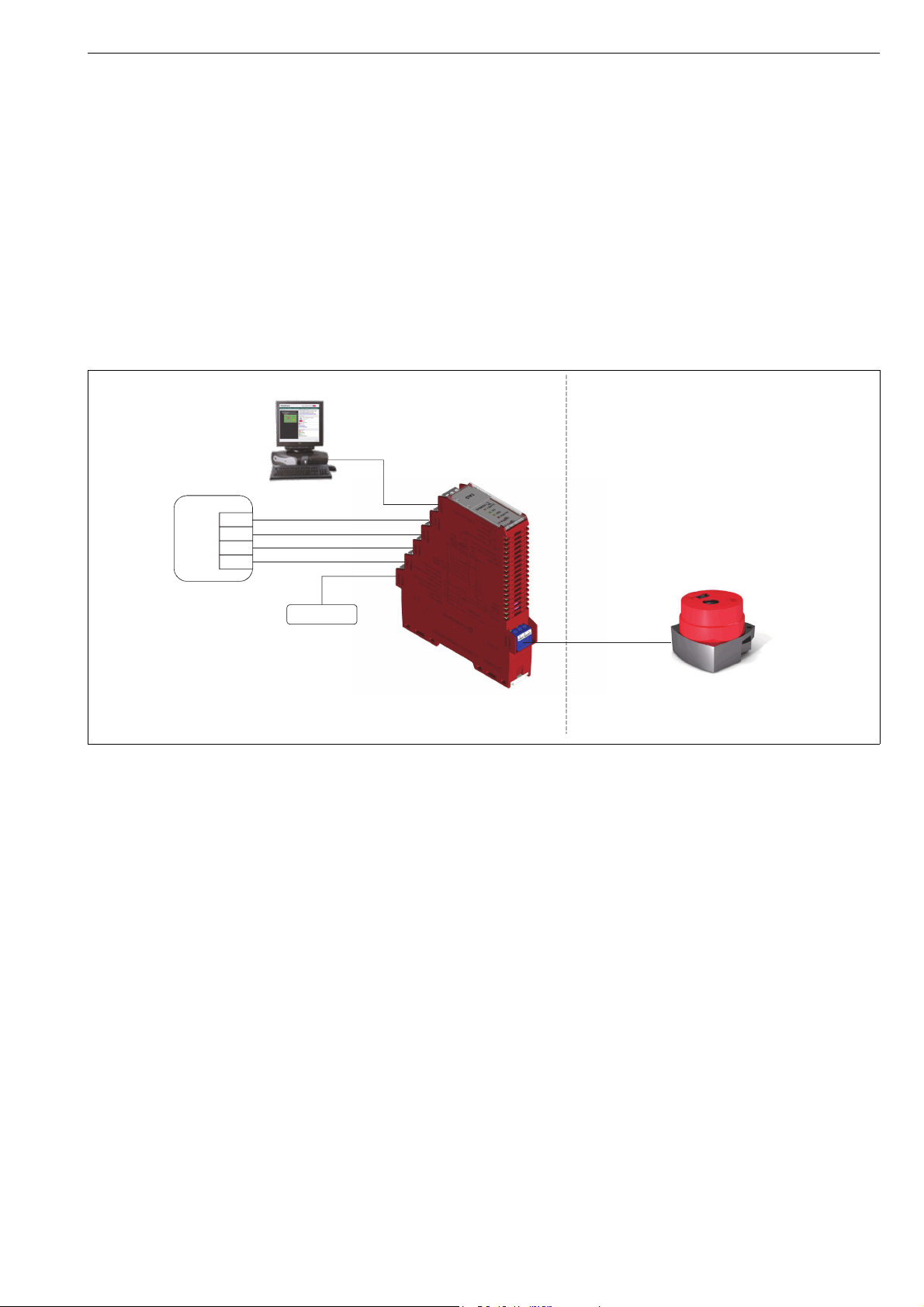
RCI9H2 is meant to be used together with Neles ValvGuard
VG9000H intelligent safety solenoid. It is needed when 24
VDC output (DO) is used in the safety system. RCI9H2 is con-
nected between the safety system and the field device
VG9000H as presented in Figure 1. The primary function of
RCI9H2 is to convert safety binary input from a safety DO
(Digital Output) system into a SIL 3 compatible 4-20 mA
current signal. RCI9H2 also provides relay outputs for moni-
toring the test and alarm status of the VG9000H and a dis-
crete input for commanding VG9000H to start a PST (Partial
Stroke Test). Additionally, RCI9H2 includes an isolated bar-
rier and can be used in intrinsically safe application.
RCI9H2 has local interface with status relays and LED’s,
which can be used to indicate the status information of the
VG9000H (Alarm and Test status).
RCI9H2 has two configuration switches. One switch is for to
connecting RCI9H2 internal HART loop resistor (250 Ω) to
HART loop and the other switch is configuring Mode A
(HART secondary master) / Mode B (HART monitor) selec-
tion.
RCI9H2 is approved by TÜV Rheinland to be used in safety
applications up to and including safety integrity level 3
(SIL3).
2 TECHNICAL SPECIFICATIONS
Safety (input) signal:
Connection: Terminals 19+, 20-
Signal levels: 0-Signal: nominal 0 V
(-3–5 V) (leakage <2 mA)
1-Signal: nominal 24/48 V
(19–54 V DC)
Input Current: 26...38 mA (normal)
46.4 mA at 24 V DC (max)
47.9 mA at 48 V DC (max)
Max Voltage: 60 V DC
Polarity protection: -60 V DC
Over Voltage Protection: 60 V DC
Output to VG9000H:
Connection: Terminals 2+, 3-
Output current, normal mode:
0-Signal: nominal 4.2 mA,
(3.8–5.6 mA)
1-Signal: nominal 20.5 mA,
(18–22 mA)
Output current, loop powered mode 1 (power supply
not connected):
0-Signal: nominal 0 mA
1-Signal: nominal 16.4 mA,
(16–17 mA)
Output current, loop powered mode 2 (power supply
connected parallel with the safety signal):
0-Signal: nominal 0 mA
1-Signal: nominal 20.5 mA,
(18–22 mA)
Maximum load: 596 Ω
Response time: Input to output <100 ms
Power Supply:
Connection: Terminals 16+, 17-
Input voltage: 0-Signal: nominal 0 V (-3–5 V)
1-Signal: nominal 24/48 V
(19–54 V DC)
Input current: 57.4 mA at 24 V DC,
30.7 mA at 48 V DC
Max Voltage: 60 V DC
Polarity protection: -60 V DC
Over Voltage Protection: 60 V DC
Fig. 1 RCI9H2 System Level Diagram
Power supply
Safety signal
Safe Area Hazardous Area
VG9000H
DO
Safety system
4/20 mA + HART
HART
RCI9H2
Testing status
Alarm status
PST start
DI
DI
DO

47 RCI9H2 70 en
HART:
Connection: Terminals 7-, 8+ (source)
Terminals 7-, 9+ (sink)
Input current: Fixed at 11 mA,
source or sink mode
Source mode:
Output voltage max 24 V DC
External load max 600 Ω
Sink mode:
Input voltage 24 V DC (nominal)
Internal load 230 Ω
PST start:
Connection: Terminals 4+, 5-
Signal level: 0-Signal: nominal 0 V (-3–5 V)
1-Signal: nominal 24/48 V
(19–54 V DC)
Signal type: Rising edge active
Input current 4.74 mA at 24 V DC,
9.47 mA at 48 V DC
Max Voltage: 60 V DC
Polarity protection: -60 V DC
Over Voltage Protection: 60 V DC
Testing Status:
Test Status relay OFF with Test Status LED OFF -indication
Connection: Terminals 13-14 open
Terminals 13-15 connected
Test Status relay ON with Test Status LED ON -indication
Connection: Terminals 13-15 open
Terminals 13-14 connected
Relay:
Type SPDT
Current 1A (max)
Voltage 24 V (nominal)
Alarm Status:
Alarm Status relay OFF with Alarm Status LED ON -
indication
Connection: Terminals 10-11 open
Terminals 10-12 connected
Alarm Status relay ON with Alarm Status LED OFF
Connection: Terminals 10-12 open
Terminals 10-11 connected
Relay:
Type SPDT
Current 1 A (max)
Voltage 24 V (nominal)
Ambient conditions:
Ambient temperature range: -20° to +60 °C
Mechanical specifications:
Protection degree: IP20
Weight: Approx. 215 g
Dimensions: 51.5 x 136.2 x 25.2 mm
Mounting: On 35 mm DIN mounting rail
acc. to EN 60715
Data for application in connection with Ex-areas:
ATEX/IECEx: Ex II (1) G [Ex ia Ga] IIC
cCSAus: Canada: [Ex ia] IIC
Class I, Division 1,
Groups A, B, C, D
U.S.: [AEx ia] IIC
Class 1 Zone 0, Class I,
Division 1, Groups A, B, C, D
Ex values: Uo = 24.5 V
Io = 93.6 mA
Po = 595 mW
Co = 0.117 μF
Lo = 4.29 mH
Approvals
Safety: Certified by TUV Rheinland
up to and including SIL3
according to IEC61508
IECEx: IECEx Sira 13.0014X
ATEX: Sira 13ATEX2026X
cCSAus
Electromagnetic compatibility:
According to EN61326,
EN61000-6-2, EN61000-6-4
3 RECYCLING AND DISPOSAL
Most parts can be recycled if sorted according to material.
Most parts have material marking. In addition, separate
recycling and disposal instructions are available from the
manufacturer. Device may also be returned to the manufac-
turer for recycling and disposal. There will be a charge for
this.
4SAFETYPRECAUTIONS
The quoted entity parameters of Co and Lo are applicable
for the distributed capacitance and inductance in cable.
Where there is circuit capacitance or inductance in the con-
nected equipment (represented by Ci and Li respectively),
then these values shall not exceed 50% of the quoted Co
and Lo.
5 TRANSPORTATION, RECEPTION AND
STORAGE
The RCI9H2 is a sophisticated device, handle it with care.
Check the device for any damage that may have
occurred during transportation.
Store the device preferably indoors; keep it away
from rain and dust.
Do not unpack the device until installing it.
Keep the original packaging. Always store and trans-
port the device in the original packaging.
Do not drop the device.

7 RCI9H2 70 en 5
6 INSTALLATION
6.1 Mounting
Open the two DIN rail retaining clips on the bottom of the
device. Mount the device onto the DIN mounting rail. Push
the retaining clips inwards to lock the device to the DIN rail.
Low heat dissipation of the device allows vertical and hori-
zontal wall mounting without spacing.
6.2 Dimensions
The mechanical dimensions of the device are shown in
Chapter 9.
6.3 Electrical connections
Safety Signal
Connect the safety signal (19-54 V DC) from the
safety system DO to terminals 19 +, 20-.
This signal controls the input signal to VG9000H (4/
20 mA).
Power Supply
Normal mode
Connect 24 V DC or 48 V DC power supply to termi-
nals 16+, 17-.
Loop powered mode 1
If power supply is disconnected, it will not affect the
valve position, but the HART communication, PST
input and Test & Alarm relays are not active.
Loop powered mode 2
Power supply can also be connected in parallel with
safety signal. In that case, the RCI9H2 is fully func-
tional (i.e. HART communication, PST input and Test
& Alarm relays are active) while safety signal is in “1”
state (19-54 V DC).
Signal to VG
Connect the VG9000H field wire to power supply can
also be terminals 2+, 3-.
Cable shall be one or more single-twisted pair
shielded or multiple-twisted pair with overall shield.
Single and multiple pair may be combined in a given
network provided all current input devices associ-
ated with multiple pairs of the same cable shall be
located nominally at one end of the multi-pair cable.
Unshielded cable may be used if it is demonstrated
that ambient noise or crosstalk does not affect com-
munication or functions of the ValvGuard.
HART communication
Source mode:
Connect HART master (e.g. HART multiplexer or
modem) without external power supply to terminals
7-, 8+. RCI9H2 is in current source mode and supplies
the 11 mA current to the HART terminals.
HART communication loop requires a load to be
present in the loop. This load can be set by the
switch S1. In this case the switch S1 needs to be set
to position III. In position III the HART loop resistor is
coupled between terminals 7 & 8 inside the device.
In position II the HART loop resistor is not coupled.
Do not set the switch S1 to position I in this case.
Sink mode:
Connect HART master (e.g. DCS AI), which is provid-
ing power to terminals 7-, 9+. RCI9H2 is in current
sink mode and does not supply the current to the
HART terminals. RCI9H2 will control the loop current
to the 11 mA.
HART communication loop requires a load to be
present in the loop. This load can be set by the
switch S1. In this case the switch S1 needs to be set
to position I. In position I the HART loop resistor is
coupled between terminals 7 & 9 inside the device.
In position II the HART loop resistor is not coupled.
Do not set the switch S1 to position III in this case.
PST Start
Partial Stroke Test can be started remotely via
RCI9H2 by providing binary signal (19-54 V DC) to
terminals 4+, 5-. The rising edge of this signal com-
mands VG9000H to start PST. VG9000H will run the
manual PST test, which is programmed in it's mem-
ory. The switch S2 need to be in position I to make
this input active.
Testing Status
Connect testing status output to relay terminals 13,
14 (normally open) or 13, 15 (normally connected).
When testing is active the relay is exited, resulting
terminals 13, 14 to be connected and terminals 13,
15 to be open.
The testing status is only available if the system is
configured properly. Please see the Chapter 2 “Tech-
nical specifications” and Chapter 7“Commissioning
and operation”.
Alarm Status
Connect alarm status output to relay terminals 10, 11
(normally open) or 10, 12 (normally closed). When
alarm is active the relay is NOT exited, resulting ter-
minals 10, 11 to be open and terminals 10, 12 to be
connected.
The alarm status is only available if the system is con-
figured properly. Please see the Chapter 2 “Technical
specifications” and Chapter 7“Commissioning and
operation”.
Fig. 2 Wiring connections
COM
NC
NO
10
12
11
0 / 24 VDC (19-54VDC)
HAZARDOUS
ARE A
+
VG
19
20
17
16
14
15
13
89
75
4
PST
START
HART
NO
NC
COM TESTING
STATUS
19-60VDC / 100mA (max.)
0 - Sig: 0V
1 - Sig: 24/48V
SAFE AREA
2
3
+
++
+
SAFETY SIGNAL
POWER SUPPLY
SOURCE
SINK
ALARM
STATUS
+

67 RCI9H2 70 en
7 COMMISSIONING AND OPERATION
7.1 DIP Switches
The RCI9H2 has two DIP switches; switch 1 (S1) and switch
2(S2).
7.1.1 Switch S1
Switch S1 S1 is for HART loop resistor configuration. S1 con-
figuration is explained in Chapter 6.3 “Electrical connections”.
7.1.2 Switch S2
Switch S2 is for HART mode selection.
S2 position I, HART secondary master mode
In this mode, full RCI9H2 functionality is available. PST start
input is functional and ALARM and TEST status outputs are
available. HART handheld communicator cannot be used if
HART primary master is present in the HART loop. In HART
loop, there can be only two masters and the handheld
would be the third one, which is not allowed.
S2 position II, HART monitor mode
In this mode, HART handheld can be used. PST input is not
functional. ALARM and TEST statuses are available if
VG9000H is configured to send HART burst status messages
to RCI9H2. This configuration can be made via VG9000H
DTM/EDD as follows:
Set the burst mode command to 169 (Read short sta-
tus).
Set the burst mode control parameter to ON to acti-
vate the burst mode. Default is OFF.
7.2 LEDs
Fig. 3 Terminals, switches and LEDs
Signal to VG
Switch 1 (HART loop resistor)
Switch 2 (HART mode)
PST start
HART
Alarm status
Test status
Power supply
Safety signal
Alarm (red)
Test (yellow)
Power supply (green)
Safety signal (orange)
Table 1 Switch selections
Switch S1 HART loop resistor Mode / Teminals
IYesSink(7,9)
II No (factory default) Source or sink
III Yes Source (7, 8)
Switch S2 HART mode
I Secondary master
(factory default)
II Monitor
Table 2 LED message explanation
LED Name Color Function Display Reason
ALARM Red Indication of an alarm ON - VG9000H is in alarm state or
- HART Communication timeout between VG9000H
and RCI9H2 because of wrong configuration or failure
in wiring between RCI9H2 and VG9000H or
- RCI9H2 internal memory test has failed.
- RCI is in monitor mode, but the burst mode is OFF in VG
OFF - No active alarms or errors
- If alarms are active in VG, but the RCI power supply is not
connected, they won’t be shown in RCI.
TEST Yellow Indication of partial stroke test ON VG9000H has on-going test or test warning time has started.
NOTE: Test LED / status relay is showing the test warning time
with VG9000H firmware revision 1.32 and onwards when using
the HART monitor mode.
OFF No test is running
OK Green Indication of presence of
power supply ON Power supply is present, no alarm
OFF Power supply not present or device is faulty
Blinking Power supply is present and alarm is active
SAFETY Orange Indication of presence of
safety signal ON Safety signal is present.
OFF Safety signal is not present.
- Safety system DO is in “0”state or
- Safety signal is not connected to terminals or
-Failureinwiring

7 RCI9H2 70 en 7
8 MAINTENANCE
If RCI9H2 unit becomes faulty, the complete unit needs to
be replaced with a new unit.
Replace the unit by following these instructions.
1. Note that the replacement of the RCI9H2 will
disconnect VG9000H from operation and the valve
will move to fail-safe position.
2. Pull out the wire terminals by help of a small flat
screwdriver. Make sure that you are able to
reconnect the terminals in the same order.
3. Pull the DIN rail retaining clips outwards using a flat
screwdriver.
4. Take RCI9H2 off the DIN rail and replace with a new
one.
5. Push the DIN rail retaining clips inwards to lock the
unit to the DIN rail.
6. Push wire terminals back to the RCI9H2. Make sure
that you reconnect the terminals in the correct
positions.
7. No special tools needed for maintenance.
9 DIMENSIONS
25.20
151.5
146.0
136.2
Metso Flow Control Inc.
Europe, Vanha Porvoontie 229, P.O. Box 304, FI-01301 Vantaa, Finland. Tel. +358 20 483 150. Fax +358 20 483 151
North America, 44 Bowditch Drive, P.O. Box 8044, Shrewsbury, M A 01545, USA. Tel. +1 508 852 0200. Fax +1 508 852 8172
South America, Av. Independéncia, 2500-Iporanga, 18087-101, Sorocaba-São Paulo, Brazil. Tel. +55 15 2102 9700. Fax +55 15 2102 9748
Asia Pacic, 238B Thomson Road, #17-01 Novena Square Tower B, Singapore 307685. Tel. +65 6511 1011. Fax +65 6250 0830
China, 11/F, China Youth Plaza, No.19 North Rd of East 3rd Ring Rd, Chaoyang District, Beijing 100020, China. Tel. +86 10 6566 6600. Fax +86 10 6566 2583
Middle East, Roundabout 8, Unit AB-07, P.O. Box 17175, Jebel Ali Freezone, Dubai, United Arab Emirates. Tel. +971 4 883 6974. Fax +971 4 883 6836
www.metso.com/valves
87 RCI9H2 70 en
10 EC DECLARATION OF CONFORMITY
EC DECLARATION OF CONFORMITY
Manufacturer:
Metso Automation Oy
01301 Vantaa
Finland
Product: Remote communication interface RCI9H2
Approvals:
Approval EC Type examination Certificate
(EMC 2004/108/EC) EN61326,
EN61000-6-2, EN61000-6-4
TÜV 01200131001
Ex II (1) G [Ex ia Ga] IIC Sira 13ATEX2026X
Applicable directives:
EMC 2004/108/EC Electrical
ATEX 94/9/EC (until 19 April 2016)
ATEX 2014/34/EU (from 20 April 2016)
Approved and Ex marked types
As the products within our sole responsibility of design and manufacture may be used as parts
or components in machinery and are not alone performing functions as described in Article 6(2)
in the Machinery Directive (2006/42/EC), we declare that our product(s) to which this
Declaration of Conformity relates must NOT be put into service until the relevant machinery into
which it is to be incorporated has been declared in conformity with the provisions of the
Machinery Directive.
The product above is manufactured in compliance with the applicable European directives and
technical specifications/standards.
Protection from e.g. static electricity caused by the process or connected equipment must be
considered by the user (EN 60079-14 §6).
The product do not possess any residual risk according to hazard analyses made under the
applicable directives providing that the procedures stated by the Installation, Operation and
Maintenance manual are followed and the product is used under conditions mentioned in the
technical specifications.
Manufacturer´s certificates:
Standard / Directive Notified Body Certificate No.
ISO 9001:2008 DNV 73538-2010-AQ-FIN-FINAS
ATEX 94/9/EC Annex IV DNV 0575 DNV-2006-OSL-ATEX-0260Q
Vantaa 7th January 2016
Ralf Liljestrand, Manager, Product safety and compliance
This manual suits for next models
1
Table of contents
Other Metso Recording Equipment manuals


