CMS CMI-01
CMI-01_Eng.doc Oct. 1, 2004 / BL 3(4)
2 DESCRIPTION
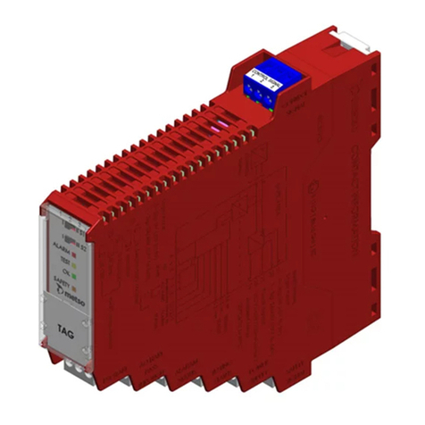
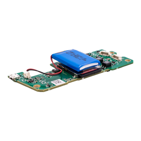
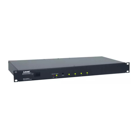
The CMI-01 is an interface unit for the CMS Control Motor System.
The unit is mounted into the card slots of the rack unit (CMR-01).
The CMI-01 Control Motor Interface is used in combination with the control motor driver, CMD-
RM1. Together they will form an interface to control 5-phase or 2-phase stepping motors.
Control Motor function:
The unit is controlled by activations of the control input modules of the Control Motor Rack, CMR-
01. The CMI-01 generates pulses in three different modes:
SINGLE STEP MODE: A single control input pulse, less than 500 ms, will generate a corresponding
number of pulses that will move the refiner disc 0.01 mm.
LOW-SPEED MODE: When the control input pulse is longer than 500 ms, it will generate a
frequency of pulses that will move the refiner disc with a speed of 0.05 mm/second.
HIGH-SPEED MODE: When the control input pulse is longer than 500 ms, and high speed input is
active, it will generate a frequency of pulses that will move the refiner disc with a speed of 0.25
mm/second.
Due to variation of the thread pitch on the control rod, 4 different sets of pre-adjusted frequencies can
be selected depending of the adjusting screw and type of refiner. (See settings in chapter 4, page 4).
Both the low-speed and the high-speed frequencies can also be adjusted by multi-turn potentiometers
in the front of the unit.
When zero torque input signal (DI+CMT) is active, the unit will generate an output signal to the
CMD-RM1 or CMD-RM2 unit, and that will enable the holding torque of the motor.
3. TECHNICAL DESCRIPTION
Article no: CMI-01 / VAL0122827 / SKC9154971
Power supply: +10 Vdc, ± 20%, 0.5 A, max
Internal supply: +5 Vdc, not isolated from the power supply
Board dimension: L=160 mm, W=100 mm, T=30 mm (6TE)
Panel adjustments: HIGH SPEED,LOWSPEED: 15-turn potentiometers
Panel adjustment limits: 50 to 150 % of nominal setting
Panel input indicators: -><-, >--<, HIGH SPEED: Yellow led's indicating activated inputs
ALARM, Red led indicating when the alarm output is deactivated
Alarm input: From the relay output on CMD-RM1 / CMD-RM2 unit
Control inputs: Opto isolated digital input from the control input module
Input resistance: 2 kΩ. Voltage level: 5 Vdc
DI+CMTO Plates together
DI+CMAP Plates apart
DI+CMHS High speed
Optional Control inputs: Opto isolated digital input from the motherboard of the CMR-01
DI+CMT Holding torque. The holding torque is applied to the motor when not
running, if this input is connected to the U+CM output
DI+CM3 Not implemented
Alarm output: Transistor output for the relay on the motherboard of the CMR-01
Max current, 0.1 A
DO+CMAL Control motor alarm. It is normally activated, but is deactivated when the
alarm input is deactivated and approx. 5 s during power-up of the unit.
Optional outputs: Opto isolated P-channel output. PNP transistor connected to the positive
voltage of the CMD unit. The negative voltage is CM-GND (K4/12 of
CMR-01). Max current, 0.1 A.
DO+CM4 Not implemented
