Metz 601-M2 User manual

for 100 Hz TV sets with chassis 601-M2
When carrying out repairs, remember that various components carry mains voltage. After any work on
the set, ensure that it is electrically safe in accordance with the applicable regulations. Only original spa-
re parts may be used when replacing components or assemblies with the safety code í.
In order to ensure safe operation of the TV set, only original spare parts may be used when replacing
components with special specifications, which are marked with .
If you move any wires or remove any covers during the course of the work, always replace them in their
original positions after completing the work.
After each repair, the TV set must be tested in accordance with VDE 0701/Part 200. For further details,
see our Technical Information No. 02/88.
S
TV. VIDEO. AUDIO. MECABLITZ
AA
AALL
LLII
IIGG
GGNN
NNMM
MMEE
EENN
NNTT
TT
II
IINN
NNSS
SSTT
TTRR
RRUU
UUCC
CCTT
TTII
IIOO
OONN
NNSS
SS
Metz-Werke GmbH & Co KG
Postfach 1267 •D-90506 Zirndorf
Telefon (0911) 9706-0 • Telefax (0911) 9706-340
Chassis, view on component side
Errors excepted. Subject to technical 601 46 9022.A1
03/03/16
☞

When carrying out repairs, remember that
various components carry mains voltage. After
any work on the set, ensure that the mains isola-
tion is fully established..
1. Supply voltages and high voltage
The supply voltages must be measured and adju-
sted with the aid of a DC voltmeter with an accu-
racy of at least 0.3% !
With the beam current set to "0", use R 1896 on the G
chassis to adjust the voltages D138 and D140 to the
values shown in Table 1. If there are no faults, the high
voltage should then be as shown in the table:
If the voltages D138, D140 are set correctly, the secon-
dary voltage of the power supply unit and the voltages
generated by the line transformer will automatically
have the correct values (see Table 2).
Never attempt to correct the picture width by adju-
sting the voltages D138 or D140 (R 1896) !
2. Configuration
The settings in the menu "Configuration" need to
be changed only if you have replaced the
EEPROM, a tuner or the CRT.
In the "Service menu" (see Section 3), use the blue key
to select "Configuration". The red cursor points to
"Language". Use the cursor control key to select
"Hardware" and then press "OK". Depending on
which component you have changed, it may be neces-
sary to set all parameters to new values or only those
for the changed component.
In the lines "CRT" and "Tuner", you can select the
appropriate type from a list.
Take care to select the correct type in each case
(see Table 1). If you select an incorrect CRT type,
the maximum beam current may be exceeded,
resulting in a reduced CRT lifetime.
2.1 Initialising the EEPROM
When you initialise the EEPROM, all stored data
will be lost! The EEPROM is filled with suitable initi-
al values.
In the "Service menu", use the red key to select "Init.
memory". The red cursor now points to "Data
memory". Use the cursor control key or press the "OK"
key to move to the file card labelled "Initialisation".
Press the "OK" key to confirm your selection and then
use the cursor control key to move to "Initialise". Press
the "OK" key again to confirm this selection and then
use the -+key to select "Yes". Press the "OK" key
again to start the initialisation procedure
3. Service menu
The "Service menu" is called as follows:
- Switch off the TV set with the main power switch.
- Press and hold any two keys on the control panel of
the TV set until the green LED lights and switch the set
on with the main power switch.
- The service menu is now displayed. The software ver-
sion number is displayed below the Metz logo.
The service menu is divided into three submenus:
- Configuration
- Adjustment
- Memory initialisation
Basic operating procedures
In the service menu, you select the desired submenu
with the key of the same colour on the remote control
unit. You select the various functions with the oval cur-
sor control key
- The INFO (Help) key has no function in the service
menu.
- Pressing the TV key terminates the service mode and
switches the TV set back to its normal operating
mode.
- The MENU key moves you from any menu item to the
next higher level of the menu tree. From the main
menu, it switches the set back to the TV picture.
- Pressing the OK key saves any changes you have
made to the settings.
You can now switch programmes. Pressing the MENU
key again returns you to the service menu.
☞
☞
☞
☞
☞
2
Table 1: Voltages
*) see also Section 3.1.3
Coloured keys:
call menu
TV: return to TV
picture
Adjustment
Init.memory
TV-Menü
Configuration
MSM 601 V1.0
D 138
D 140
High
voltage
Chassis
CRT type
A80 EJX 11X429 601 G1 0081
32 KV140 V
PF84
Um *)
A68 ELR 50X71 601 G1 0073
32 KV138 V
PA72
800 mV
800 mV
W76 ERF 342X044 601 G9 0083
32 KV138 V
RF82
800 mV

3.1 Adjustment
3.1.1 Adjusting the screen-grid voltage Ug2
The screen-grid voltage of the CRT is set to a
value which depends on the model and should
not be changed.
The only exception to this is if you have replaced
the diode split transformer, the CRT, the BV
module or the KS module.
In the "Service menu", use the yellow key to select the
menu item "Adjustment". The set then displays a card
file with the red cursor pointing to "Video". Use the
cursor control key to select the item "Ug2 adjustment"
Press the OK key to display the Ug2 test pattern. Turn
the screen-grid adjustment control Ug2 (the bottom
control on the line transformer) fully counterclockwise
and then turn it slowly clockwise until the red bar on
the screen changes to green. Turn the control further
until the bar changes back to red. Then turn the control
back slightly until the bar changes back to green.
Press the OK, MENU or TV key to return to the TV pic-
ture.
3.1.2 Focus adjustment
Prerequisite: the screen grid voltage Ug2 must be
set correctly before the focus is adjusted.
On the TV sets, there are two focus controls on the DF
module (focus block). The control "Focus 1" acts pri-
marily in the vertical direction, the control "Focus 2"
primarily in the horizontal direction. The two controls
affect each other slightly, which means that it may be
necessary to adjust them alternately. Judge the focus at
the centre of the screen and adjust the controls for the
best results.
3.1.3 Adjusting the peak white level
This setting must always be made after replacing
the KS module, the video processor IC 3101, the BV
module, or the CRT, after adjusting the screen-grid
voltage and after initialising the EEPROM.
Connect the following measuring circuit between test
point ◊63 (anode of D 5580) and ground:
Prerequisite: The Ug2 voltage must be correct
(see Section 3.1.1). The voltage drop across the
100 ( resistor is proportional to the peak beam
current: 100 mV = 1 mA
Connect an oscilloscope to the 100 Ωresistor of the
measuring circuit.
In the "Service menu", use the yellow key to select the
menu item "Adjustment". The red cursor points to
"Video". Use the cursor control key to select the item
"Peak white level". Press the OK key to display the test
pattern for the peak white level. Use the -+key to
adjust the pulse voltage on the 100 Ωresistor to the
value Um shown in Table 1.
Then save the setting by pressing the OK key. If neces-
sary, you can cancel the adjustment by pressing the
MENU key or TV key.
3.1.4 White balance
IIn the "Service menu", use the yellow key to select the
menu item "Adjustment". The red cursor points to
"Video". Use the cursor control key to select the item
"White balance". Press the OK key to display the test
pattern for the white balance.
The desired white balance can now be adjusted with
the -+key. You can step through the colours in the set-
tings box with the cursor control key. Note that the
colour with the highest value must be set to 31.
Then save the setting by pressing the OK key. If neces-
sary, you can cancel the adjustment by pressing the
MENU key or TV key.
3.1.5 Colour offset
In the "Service menu", use the yellow key to select the
menu item "Adjustment". The red cursor points to "Video".
Select the item "Colour offset" with the cursor control key
Press the OK key to switch to adjustment mode. Then use
the -+key to achieve the best possible coincidence of the
colour and monochrome pictures, using a suitable test pat-
tern (via the tuner; not an RGB test pattern).
Then save the setting by pressing the OK key. If neces-
sary, you can cancel the adjustment by pressing the
MENU key or TV key.
☞
☞
☞
☞
3
Initialise geometry
Geometry adjustment
Video
UG2 adjustment
VCO adjustment
UG2 adjustment
AGC adjustment
SVM factor
SVM phase
Colour offset
White balance
Peak white level
TV-Menü
Init. memory
Adjustment
Configuration
Initialise geometry
Geometry adjustment
Video
Peak white level 1
VCO adjustment
UG2 adjustment
AGC adjustment
SVM factor
SVM phase
Colour offset
White balance
Peak white level
TV-Menü
Init. memory
Adjustment
Configuration
100 Ω
Messpunkt 2,2 n 5,6 V
22 k
12 V
: select
menu item
: select
menu item

3.1.6 SVM factor and SVM phase
The menu items "SVM factor" and "SVM phase" are
automatically adjusted after initialisation of the
EEPROM.
3.1.7 VCO adjustment
The VCO adjustment must always be carried out after
replacing the quartz crystal Q5901 or the digital colour
decoder IC 5901 and after initialising the EEPROM..
A suitable test pattern (not RGB) should be used for
adjustment of the VCO (the voltage-controlled oscilla-
tor which is important for the capture range of the
colour carrier frequency). The colour carrier of the test
pattern should be as accurate as possible.
In the "Service menu", use the yellow key to select the
menu item "Adjustment". With the cursor control key,
choose the option "VCO adjustment". Press the OK key
to switch to adjustment mode. Then use the -+key to
select "No", "Yes" or "Default". Selecting "Yes" starts
adjustment of the VCO with the colour carrier of the
displayed test pattern. If no suitable test pattern is avai-
lable, you can set the VCO to a default value by selec-
ting "Default".
3.2 Colour purity
(on model Spectral-84 MF 84 TH 89 only)
On the model Spectral-84 MF 84 TH 89, the service
menu VCO adjustment contains the additional item
"Colour purity".
With this menu item, it is possible to adjust the colour
purity in all four corners of the screen with the aid of a
setting menu. A red screen is displayed to facilitate this
adjustment. Depending on the installation location and
any existing colour inpurities, it may be necessary to
change the factory setting.
Adjust the colour purity, while viewing the red screen
to detect any impurities. The four adjustments top left,
top right, bottom left and bottom right (these are also
displayed as text on the screen) may affect each other
slightly.
In the menu, you can select the four corners with the P+
and P– keys and adjust the values with the +and –
keys.
3.3 Picture geometry (no internal test pattern possible)
Selecting factory or table values:
Explanation:
Basic geometry values: The current picture geometry
settings. If the picture geometry
is changed, the new values are
stored here.
Factory geometry values: The picture geometry settings
which were made in the fac-
tory.
Table values: The picture geometry data stored in the
computer programme memory (flash
memory, IC3665), sorted by CRT diago-
nal dimension. These are identical for all
TV sets with a CRT of the same diagonal
dimension.
In the "Service menu", use the yellow key to select the
menu item "Adjustment". With the cursor control key,
first call the item "Initialise geometry" and then "Fac-
tory geometry values" or "Table values". Press the OK
key to switch to the lower settings box. The -+key now
permits you to select either "yes" or "no". Then save
the setting by pressing the OK key.
Adjusting the picture tube:
If you have replaced the EEPROM (IC 2250), then:
Open the "Service menu" and use the blue key to sel-
ect "Configuration". The red cursor points to "Langua-
ge". Use the cursor control key to select "Hardware"
and press the OK key to confirm this selection. Then
use the cursor control key to select the menu item
"CRT" and press the OK key for confirmation. You can
now choose the CRT type with the -+key. Finally, con-
firm this selection by pressing the OK key.
Adjustment the picture geometry:
The picture geometry may be adjusted only with
a test pattern with a vertical frequency of 50 Hz!
In the "Service menu", use the yellow key to select the
menu item "Adjustment". Use the cursor control key to
select the item "Geometry adjustment" and press the
OK key to confirm this selection. Then use the cursor
control key to select the desired geometry correction
and confirm this by pressing the OK key.
You can now adjust the selected value with the -+key.
Save the changed setting by pressing the OK key. By
repeating the above steps, you can adjust any or all of
the following geometry settings sequentially:
• Vertical picture position
• Picture amplitude: adjust for an overscan of 3%.
• Horizontal picture position
• Picture width
• East-West parabola
• East-West trapezoid
• Corner correction, top
• Corner correction, bottom
☞
4
Initialise geometry
Geometry adjustment
Video
Top left 0 Top right 0
Bottom left 0 Bottom right 0
: select
menu item
Colour purity
VCO adjustment
UG2 adjustment
SVM factor
SVM phase
Colour offset
White balance
Peak white level
TV-Menü
Init. memory
Adjustment
Configuration

• Extreme corner correction
• Vertical linearity: adjust with the -+key so that the
amplitudes of the top, middle and
bottom boxes are equal.
• Vertical parallelogr.: use the -+key to tilt the picture
to the right or left to compensa-
te for any asymmetrical trape-
zoid distortion
• Vertical bending: use the -+key to compensate for
any bending of the vertical lines in
the test pattern.
• Vertical S-correction: use the -+key to adjust the
middle box in the test pattern to
the same height as the top or
bottom box
The following factory settings should be changed
only if absolutely necessary.
• Vertical EHT compensation: use
use -+key to cancel out any variations of the picture
amplitude as the beam current varies.
• Horizontal EHT compensation:
use -+key to cancel out any variations of the picture
width as the beam current varies.
• AFC EHT compensation:
use -+key to cancel out any asymmetrical trapezoid
distortion in particularly bright areas of the picture
by tilting the entire field.
After completing the adjustments, press the MENU key
to return to the "Service menu".
4. Brief descriptions with servicing hints
4.1 Power supply unit
On the chassis 601 G1..., the supply voltages are divi-
ded into the following groups:
The D voltages
The D voltages are generated by the switching power
supply and are about 20% higher during "operation
without H deflection" than in normal TV mode.
The DS voltages
These are derived from the D voltages and are present
in both normal TV mode and "operation without H
deflection". They are switched off in standby mode.
The C voltages
These voltages are generated by the line transformer
and are present only in normal TV mode.
4.2 Standby control
In standby mode, the power supply unit operates in pul-
sed mode. The power supply unit is switched on for
about 20 ms and then switched off for about 400 ms.
As a result of this, there is a sawtooth voltage superim-
posed on the D voltages.
The standby function is activated by the control line
STBY (L state).
The transistors Tr 1870, Tr 1880, the optocoupler
LK1740, and the transistors Tr 1730 and Tr 1890 all
conduct. Transistor Tr 1881 is cut off, the ON line is
"high" and the DS voltages are all switched off.
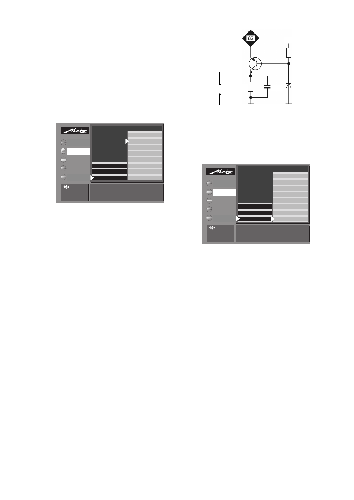
When the voltage D25 reaches the threshold of D1890
(12 V), transistor Tr 1891 conducts. This causes IC
1735 to cut off transistor Tr 1710 until the IC supply vol-
tage (pin 14) drops to 8 V. A new cycle is then started
via the start-up circuit.
For faultfinding, this pulsating mode (ecological stand-
by mode) can be disabled by removing the service
strap S2 (the TV set then runs in service standby mode).
The DS voltages remain switched off.
4.3 The switching stage
The supply voltages needed for operation of the TV set
are generated in the switching stage and the line out-
put stage.
The switching stage is a self-starting blocking oscillator
whose transformer T 1705 acts as a protective isola-
ting transformer on the mains side. The regulation cir-
cuits of the switching stage compensate for variations
in the mains voltage and in the currents drawn by the
circuits of the TV set.
The switching stage receives the rectified mains voltage
A 300. R 1701 and R 1702 provide a start-up voltage
for the central component of the power supply, IC
1735, when the TV set is switched on.
During normal operation (and also in standby mode),
IC 1735 receives its voltage from the winding 16/14
of transformer T 1705 and the rectifier circuit D
1733/C 1736.
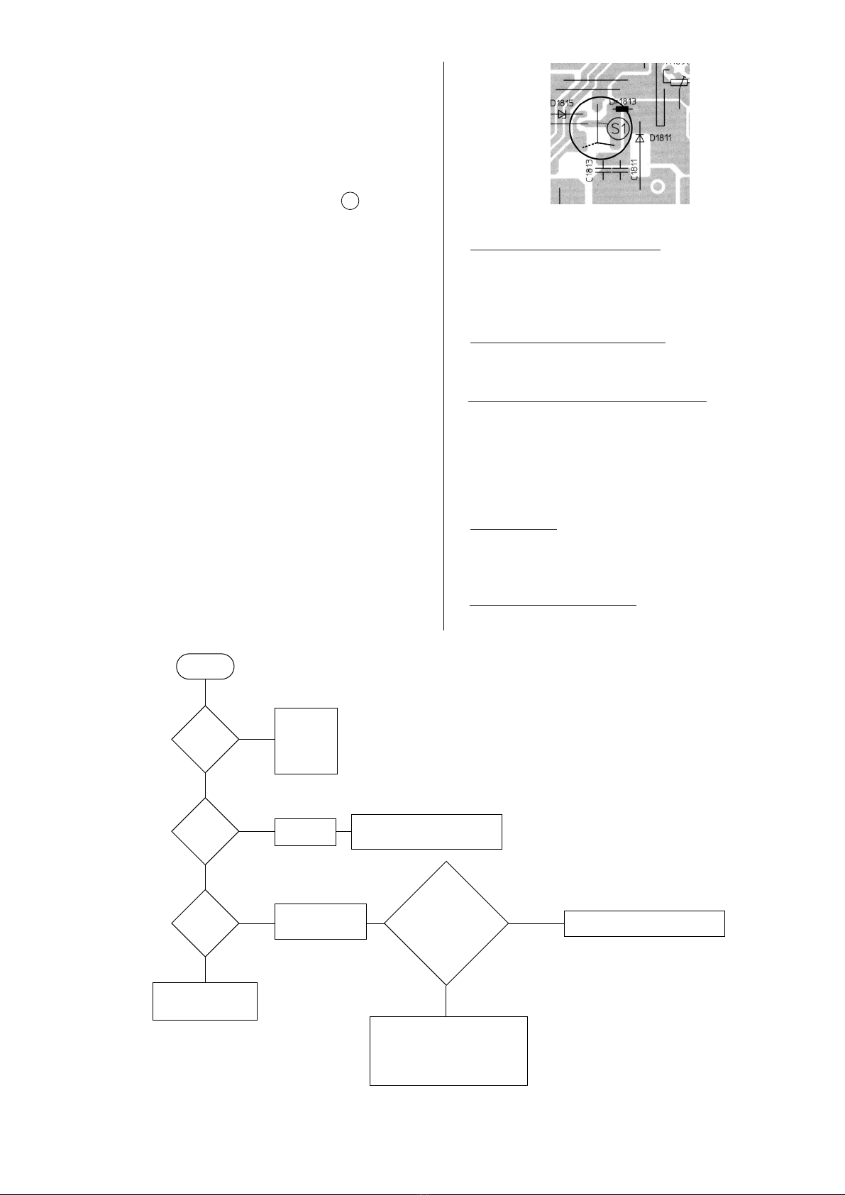
4.3.1 Checking the switching stage
Unsolder service strap S1 (in the horizontal out-
put stage) or remove the plug GD1!
In this mode, the supply voltage D150 is about 50%
higher than shown in the circuit diagram. The supply
voltages D24, D25, D16 and D8 are protected by nor-
mal fuses. If one of these fuses blows, examine the
related parts of the circuit.
Never operate the switching stage without a
basic load connected. In other words, never
remove all of the diodes D 1811, D 1821,
D1831, D 1841, D 1851 and D 1861 simulta-
neously. In addition, never remove the fuses Si
1821, Si 1831, Si 1841 and Si 1851 and simulta-
neously operate the TV set with a reduced mains
voltage.
☞
☞
☞
5

6
4.4 Service notes for the horizontal output stage
All supply voltages derived from the horizontal output
stage are protected by means of fuse-resistors which
disconnect the defective circuit section from the diode
split transformer in the case of a fault.
For faultfinding in the deflection circuit, the horizontal
output stage can be operated with a reduced supply
voltage by unsoldering the service strap S1 and
moving it to the other position (dotted line in picture on
the right). The horizontal output stage now runs from
the D 25 voltage, which is about 15% of its normal
supply voltage.
This means that all pulse and supply voltages of the
horizontal output stage are about 15% of the values
shown in the circuit diagram. The waveforms do not
change. Since the vertical deflection is not running, the
vertical parabola is not superimposed on some of the
waveforms when they are measured with an oscillos-
cope. Incorrect waveforms and/or deviations from the
reduced (15%) values of the voltage indicate the possi-
ble cause of the fault.
4.5 Monitoring circuit
Faults in the high-voltage generator and CRT control
circuits are detected by a monitoring circuit. This circuit
consists primarily of the transistors Tr 1301 and Tr
1302. If this circuit is triggered, Tr 1302 cuts off and
initiates a power-off function via the control line
HPROT (this occurs if the HPROT pulses become grea-
ter than 4.5 V). The TV set then switches to standby
mode.
The following individual parameters are monitored:
a) An increase in the high voltage
The positive amplitude of the g-pulse from the line
transformer is evaluated (this acts directly on input
HPROT of IC 3301, SDA 9380; Tr 1302 is not
affected).
b) An increase in the beam current
In this case, the voltage at the terminal "B-ground"
of the diode split transformer becomes 0 Volt.
c) Arcing or a short-circuit in a spark gap
In this case, the voltage at the terminal "B-ground"
of the diode split transformer becomes very positi-
ve. In cases a), b) and c), the TV set switches itself
off. After three unsuccessful attempts to restart, the
TV set switches permanently to standby mode and
the standby LED blinks five times.
d) Voltage DS12
If the DS12 voltage drops below 9 V as the result of
a fault, Tr1303 cuts off, Tr1301 conducts and
TR1302 cuts off.
e) H driver stage, H deflection
If the H deflection becomes unstable or operates
with an incorrect pulse-pause ratio, Tr1390 con-
ducts and Tr1302 cuts off.
For faultfinding in the horizontal and vertical deflec-
tion circuits, the monitoring circuit can be temporari-
ly disabled by connecting the pin HPROT (Pin 11 on
GKS 3) to ground. In this state, the screen is dark,
but the horizontal and vertical deflection circuits
receive the normal input signals.
☞
Switch on
the TV set
A300
330 V ?
Mains switch
D 1701
D 1703
D 1705
R 1704
Si 1703
R 1705
open-circuit?
Clocked
whistling noi-
se audible?
Short-circuit in C 1812
or
Short-circuit deflection
Connect oscilloscope
or voltmeter to C
1736
Short-circuit in
Tr 1710
no
no
no
yes
yes
no
yes
yes
Open-circuit in R 1701 or R 1702
Check Tr 1730 and D 1811 for
short-circuit
Voltage at C 1736 has
sawtooth waveform of
8...14 V (possibly slight
"bubbling" noise
audible?)
Short-circuit in D 1733 or C 1736
IC 1735 defective
Open-circuit in D 1733 or R 1735
Open-circuit in Tr 1710
No input signal to Tr 1710
LK 1740, Tr 1892, Tr 1870, IC
1895, or Tr 1891 defective
Open-circuit in R 1706 or R 1710

7
Designation Normal operation Operation without Standby mode Circuits supplied
H deflection
• TV mode • AV copying • (eco) standby
• SAT mode • SAT recording • service standby
• AV playback • SAT radio
SM voltages
D140 140V ± 1V • 1) • 3) H output stage (601 G1 0081)
D138 138 ± 1V • 1) • 3) H output stage (601 G1 0073, 601 G9 0083)
D60 60V ± 3V • 1) • 3) V output stage (601 G1 0081)
, DS60 generation, tuner voltage DS45
D28 25V ± 2V • 2) • 4) NF output stages on G chassis 601, (NE module)
D25 25V ± 2V • • 4) SR module, MV module
D16 16V ± 2V • • 4) H drivers, generation of DS12, standby circuit
D8 7V ± 1V 6,3V • 4) Generation of DS5, DS5a, DS5b, DS3.3 standby circuit
D5 5V ± 0,3V • • AI module, MV module
Switched SM voltages
DS60 61V ± 3V • – SVM circuit (MV module)
DS45 46V ± 3V • – Tuner, SR module
DS12 12V ± 0,6 • 1,3V MV, BV, SR, TP and EA modules, OW-output stage
DS8 8V ± 0,4V • – AI, MV and EA modules
DS5 5,2V ± 0,2V • – MV and EA modules
DS5b 5,2V ± 0,2V • – SR and TP modules
DS3,3 3,3 ± 0,2V • – MV module
H output-stage voltages 5)
C215 215V – – RGB output stage (BV module)
C14 14,5V – – V output stage
-C14 -14,5V – – V output stage, (601 G1 0073, 601 G9 0083)
-16V – – V output stage, (601 G1 0083)
1) Approx 20% higher than in normal mode
2) AV copying and SAT recording: approx. 15% higher; SAT radio: same as in normal mode
3) Approx. 25% lower than in normal mode
4) Lower than in normal mode, with superimposed sawtooth waveform
5) Setting the voltage D140/142/150 with R1896 (with beam current 0) to the values shown in the table automatically sets the H output
stage voltages to their correct values.
Table 2: Supply voltages from the switching stage (SM) and the diode split transformer (H output stage).
Table of contents
Other Metz LED TV manuals

Metz
Metz Linea FHDTV 100 User manual

Metz
Metz Taris 43TY84 UHD twin R Installation instructions

Metz
Metz Clarea User manual

Metz
Metz Cosmo Series User manual

Metz
Metz 55MOC9010Y Installation instructions

Metz
Metz 65MOC9001Z Installation instructions

Metz
Metz 55MOC9010Z Installation instructions

Metz
Metz Calea 43TY62 User manual

Metz
Metz Taris 43TY89 UHD twin R Installation instructions

Metz
Metz 55MOC9011Z Installation instructions