Metz Eta Plus ELC PE22B Series Guide

ELC PE22B-PE35B V1.0-05.19-GB Subject to technical alterations
UV-
TECHNOLOGIE
Technical Documentation
ELC®PE22B - ELC®PE35B
eta plus electronic gmbh
Lauterstraße 29, 72622 Nürtingen, Telefon +49 7022 6002-80, Fax +49 7022 65854, E-mail: inf[email protected], www.eta-uv.de
Eingetragen unter HRB 724321 AG Stuttgart, USt.-Id.-Nr. DE 146267800, Geschäftsführer: Uwe Uhlemann

ELC PE22B-PE35B V1.0-05.19-GB Subject to technical alterations
ELC®(„Electronic Lamp Control“) is a registered trademark of
IST Metz GmbH.

Contents page I
ELC PE22B-PE35B V1.0-05.19-GB Subject to technical alterations
Contents
Safety ................................................................................................ 1
1.1. Definition of Symbols ...................................................................................1
1.2. Safety Advice................................................................................................1
1.3. Correct operation.........................................................................................2
1.4. Extended use................................................................................................2
Description of functions .................................................................... 3
Installation........................................................................................ 4
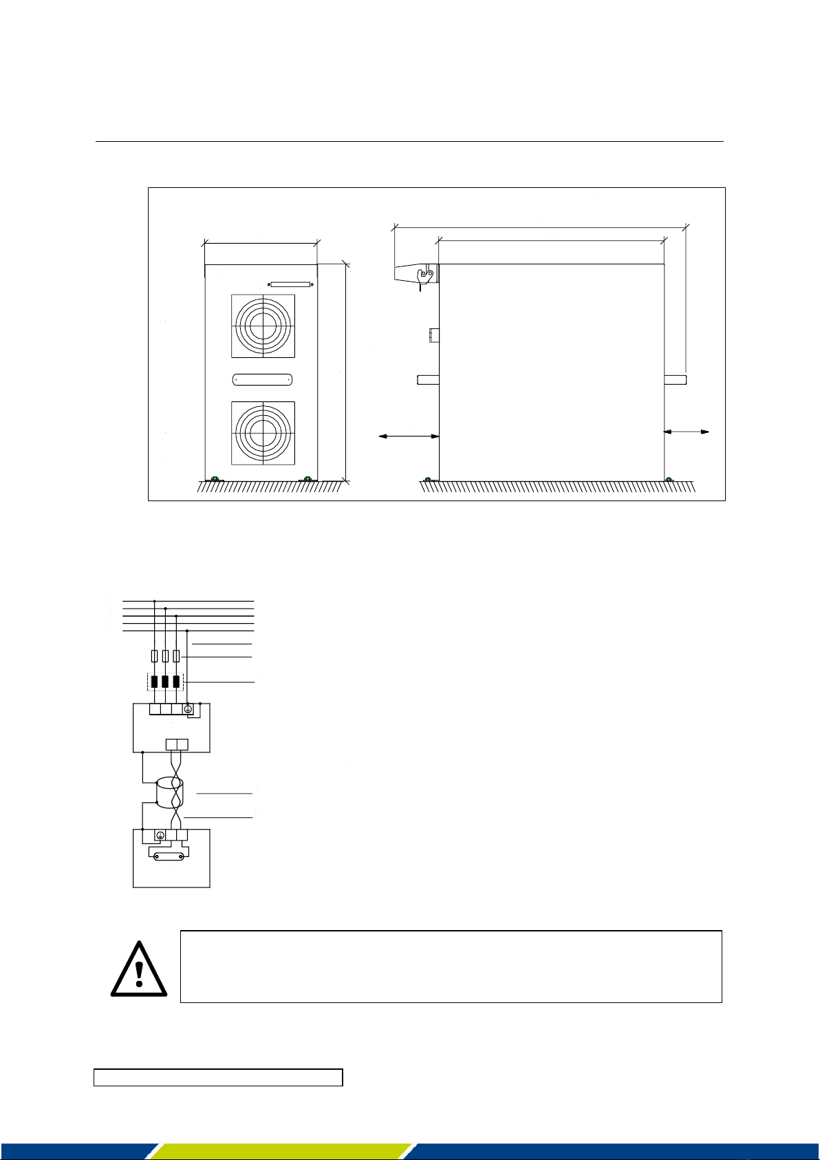
3.1. Mounting of casing .......................................................................................4
3.1.1. Vertical installation position............................................................................. 5
3.1.2. Horizontal installation position ........................................................................ 6
3.2. Power connections.......................................................................................6
3.2.1. Mains connection ............................................................................................. 7
3.2.2. Connecting the lamp feeder cable ................................................................... 7
3.3. Control- and bus connections ....................................................................10
3.3.1. Mounting of the strain relief............................................................................10
3.3.2. Connecting bus cables ....................................................................................10
3.3.3. Coding and pin assignment.............................................................................12
3.4. Comments on the safety functions of the ELC ...........................................16
3.4.1. Safety relay......................................................................................................16
3.4.2. Initialisation signal ..........................................................................................16
3.5. Configuration .............................................................................................17
3.5.1. Setting up the PROFIBUS address..................................................................18
3.5.2. Checking the PROFIBUS connection...............................................................18
3.5.3. Setting lamp power via PROFIBUS..................................................................19
3.5.4. To read out ELC serial number and softwareversion .....................................21
3.5.5. Temperature derating for PE35B....................................................................22

Contents page II
ELC PE22B-PE35B V1.0-05.19-GB Subject to technical alterations
Operation of ELC ............................................................................. 23
4.1. Initial operation..........................................................................................23
4.2. Switching on the ELC..................................................................................23
4.3. Activating the safety circuits......................................................................23
4.4. Switching on the lamp................................................................................23
4.5. Dimming operation.....................................................................................25
4.6. Standby operation ......................................................................................25
4.7. Use of the control outputs “Digital I/O” .....................................................26
4.7.1. User Register ..................................................................................................26
4.7.2. DO3 external fan control .................................................................................27
4.8. Switching off the lamp ...............................................................................27
Monitoring, warning, error, repair ................................................. 28
5.1. Mains voltage monitoring ..........................................................................28
5.2. Earth fault control......................................................................................28
5.3. Warning messages.....................................................................................30
5.4. Error...........................................................................................................32
5.4.1. Error messages...............................................................................................32
5.4.2. Error description and trouble shooting...........................................................33
5.4.3. Resetting the error register............................................................................35
5.5. Repair ELC..................................................................................................35
Technical Data................................................................................. 36

1. Safety page 1
ELC PE22B-PE35B V1.0-05.19-GB Subject to technical alterations
Safety
1.1. Definition of Symbols
Stop (Stop Danger). This symbol warns of serious danger of severe injury to
persons. It must be strictly observed.
Attention (Warning). This symbol indicates information the non-observance of
which can lead to extensive damage to property. The safety warning must be
strictly observed.
Information. This symbol indicates key information on use. Non-observance can
lead to failure.
1.2. Safety Advice
The ELC must be installed and connected in compliance with existing regulations
and practices. This is e.g. EN 60204-1 in Europe.
Repairs on the ELC may only be carried out by the manufacturer.
The installation and starting up may only be carried out by skilled electricians.
Do not open the ELC before it is disconnected from the mains. BEWARE OF
RESIDUAL VOLTAGE! The unit may still be live up to several minutes (see label on
the ballast) after it has been switched off.

1. Safety page 2
ELC PE22B-PE35B V1.0-05.19-GB Subject to technical alterations
The ELC causes a leakage current given in chapter 6.
Safeguarding by means of leakage current protection type A and type AC
according to IEC 60755 is not permitted! The ELC operates in principle as a
frequency converter and is equipped with a mains filter whose leakage current
could activate fuse protection.
Contact to the grounding connector must always be ensured.
Additional measures must be taken to ensure that there is no danger when
touching the appliance. This could be by means of a universal leakage current
protection type B, taking into consideration the increased response threshold, or
by means of an independent equipotential connection.
1.3. Correct operation
The ELC is an electrical unit intended to be installed in the switch cabinets of
industrial high-voltage power installations. It is conceived as an electronic ballast
for the operation of lamps intended for this purpose.
Any other use is deemed as misuse. The manufacturer will not assume liability
for damage resulting from misuse.
A pre-requisite for authorised operation of the ELC is the observance of both the
operating and maintenance instructions and the safety advice.
1.4. Extended use
Extended use beyond the operating specifications as stated is not permitted.
The manufacturer will not assume liability if the equipment is used in any other
way. The operator acts at his own risk.
Any operation beyond the scope of the authorised operation is considered to be
misuse.

2. Description of functions page 3
ELC PE22B-PE35B V1.0-05.19-GB Subject to technical alterations
Description of functions
The ELC is an electronic power supply unit for the operation of gas discharge lamps with
electrical properties as described in chapter 6.
In contrast to conventional ballasts (inductive lamp ballast or transformer or transformer with
transductor), the lamp with an electronic ballast is operated with high frequency (approx.
100 kHz). The lamp does not flicker and dimming is infinitely adjustable to a range between
20 % and 100 % of the electric power or to between 15 % and 100 % of the UV radiation
respectively.
Dimming
The possibility of dimming the lamp has two advantages. Firstly the lamp can be switched to
minimum load (standby operation) during longer idle times and energy can thus be saved.
Secondly the optimum lamp power can be determined and adjusted as appropriate.
Power control
The ELC offers a high level of lamp power constancy due to its integrated power control.
Variations in operating voltage of 10 % do not affect lamp power.
Ignition device
When the lamp is switched on the ELC initiates trigger pulses to fire the lamp; a separate
ignition device is not required.
Other performance characteristics
High level of electrical efficiency.
Configuration, control and monitoring of the ELC is carried out via PROFIBUS-interface.
The ELC monitors the lamp cables for earth fault.
The lamp output potential is separated from that of the supply voltage.
The ELC is both short-circuit proof and safe in open circuit operation at the lamp output.

3. Installation page 4
ELC PE22B-PE35B V1.0-05.19-GB Subject to technical alterations
Installation
3.1. Mounting of casing
The ELC must be installed in a control cabinet with at least IP 54 protection (see
EN 60529). Operation without a control cabinet or in a control cabinet with a lower
degree of protection is not permitted.
It is only permitted to install the appliance in the positions described in 3.1.1 und
3.1.2.
When installed vertically, the control connections must be positioned at the
bottom and supply connections at the top. Installation must allow for the
minimum spacing.
The ELC should not be mounted in the immediate proximity of sensitive electronic
equipment. An appropriate distance must be maintained to scatter field
transformers or other inductors.
The flow of cool air for the ELC must be safeguarded. The ambient temperature
must not exceed the values prescribed in chapter 6.
Ventilation must be provided for the switch cabinet.
The amount of air necessary is determined by the size and positioning of the
switch cabinet, the total electrical losses and the external temperature. Please
consult your switch cabinet manufacturer. For the recommended throughput of
air please see the technical data in chapter 6.
Impure cooling air could affect the functionality of the ELC. This can be avoided by
installing a fine air filter.

3. Installation page 5
ELC PE22B-PE35B V1.0-05.19-GB Subject to technical alterations
3.1.1. Vertical installation position
Fig. 1: Assembly of the ELC, vertical installation position (all dimensions in mm).

3. Installation page 6
ELC PE22B-PE35B V1.0-05.19-GB Subject to technical alterations
3.1.2. Horizontal installation position
Fig. 2: Assembly of the ELC, horizontal installation position (all dimensions in mm).
3.2. Power connections
L3
out1
L1 L2
L1
L2
L3
N
PE
out2
earthed lead network side
automatic cutout
cable shield
lamp feeder cable
lamp assembly
ELC
power choke
Fig. 3: Power connections
Fig. 3 shows the electrical installation.
Operation of the ballasts requires a power
choke in series (see technical data chapter 6)
in order to limit the total harmonic distortion
of the line current to below 50%.
The lamp feeder cable shielding must be
connected to the ELC. To this end the
connector has an EMC screw connection (also
see: connection lamp cable).
If wished, the shielding can also be
connected to the lamp unit.
Mains supply cables and lamp feeder cables must be laid separately from
control cables.
501 mm
min. 150
650 mm
min. 150
261 mm
control connector
Steckerleiste für Steuersignale
Lufteintritt
air entrance
484 mm
Lufteintritt
air entrance

3. Installation page 7
ELC PE22B-PE35B V1.0-05.19-GB Subject to technical alterations
3.2.1. Mains connection
The cross section of the earthed wire must be at least 10 mm². The three phases must be
provided with an automatic cutout.
In order to avoid damaging the terminal pins, please do not exceed the
following torques:
PE22B:
Line:
Torque:
L1, L2, L3:
1.5 –1.8 Nm
Grounding conductor (PE):
3.0 –4.0 Nm
PE35B:
Line:
Torque:
L1, L2, L3:
2.0 –2.3 Nm
Grounding conductor (PE):
2.0 –2.3 Nm
3.2.2. Connecting the lamp feeder cable
The lamp feeder cable must correspond with the cable parameters described in
chapter 6.
Components of the connector:
connector module
hood
crimp contacts
EMC cable gland with
plastic insert

3. Installation page 8
ELC PE22B-PE35B V1.0-05.19-GB Subject to technical alterations
Preparing the lamp feeder cable:
Remove sheath
Free metal braid and put over cable sheath
Dismantle conductor
(dimensions in mm)
A suitable contact crimping tool is required of
the type:
Amphenol group C146
Part No.: VN01 025 0029 1C
Closed crimp barrels (individual contacts)
2.5mm
Top: Correct crimp connection.
Middle: Stripped part of the wire too long, gap
between insulation and crimp barrel too large.
Bottom: Stripped part of the wire too short
because conductor is not visible through
inspection hole.
Insert cable into the cable gland and bush
casing.
7,5
100 12

3. Installation page 9
ELC PE22B-PE35B V1.0-05.19-GB Subject to technical alterations
Insert crimp contacts into the connector
module until they lock into place.
Ensure that the shield evenly covers the plastic
inset of the cable gland (360° contact).
Tighten EMC cable gland.
Screw the module into the hood casing. The
picture on the left shows the recommended
orientation.
The lamp feeder cable between the switch cabinet and lamp assembly must be laid protected.
For the correct installation of the lamp assembly and lamp please observe the corresponding
manufacturer’s instructions.

3. Installation page 10
ELC PE22B-PE35B V1.0-05.19-GB Subject to technical alterations
3.3. Control- and bus connections
3.3.1. Mounting of the strain relief
Strain relief in transport position
Loosen the two screws on the cable clamp with a
2 mm hex screwdriver.
Then pull out the strain relief to the left.
Strain relief in end position
Rotate the strain relief and slide it back in from
above. Note that the washer remains between the
screw head and the strain relief.
Tighten the screws.
Attention: do not remove the two bolts holding the strain relief. They are also
fastening the board inside the ballast which might get out of position.
In addition they are specifically designed to provide a large surface for optimum
contact of the strain relief to the housing.
Attention: if it is necessary to prolong the bolts exercise extreme caution when
mounting additional parts. The built in bolts have a threaded pin size M3 to fit to
the board. This might easily crack whith high mounting torques and the ballast
would have to be replaced.
The cable lengths given in 3.3.2 might not apply anymore.
3.3.2. Connecting bus cables
In case of shielded bus cables the shielding should be attached to the strain relief.

3. Installation page 11
ELC PE22B-PE35B V1.0-05.19-GB Subject to technical alterations
Remove 85mm of the isolation.
Pull back the shield to cover 15mm of the mantle.
Drill the remaining shielding into one wire.
Cut the wires and the shield to appropriate
lengths.
Insulate the shield with a heat shrink tube.The
tube on the main wire should overlap the shield’s
tube.
Mount ferrules and insert the wires into the plug.
For the plug coding and pin assignment see
paragraph 3.3.3.
Plug in and tighten the screws of the plug.
Attach the bus cable to the strain relief with a
cable strap. The bare shield must have contact
with the strain relief.
85mm
15mm
30mm
70mm
15mm
60mm

3. Installation page 12
ELC PE22B-PE35B V1.0-05.19-GB Subject to technical alterations
3.3.3. Coding and pin assignment
The control and bus cables are connected by means of the plug connections available as
accessories.
The sockets are provided with threads. In combination with the screwable plugs this ensures
a safe connection e.g. in case of vibrations.
In order to minimise the danger of mixing up the control plugs, the sockets on the appliance
have been coded with the red code profiles. They are positioned according to the following
picture:
Fig. 4: Coding of the control plug
When the control plugs are delivered they are not coded
and cannot be connected in this condition! In order to
code the control plugs the corresponding code “nose”
must be removed (see Fig. 4). Pin 1 is marked by means
of a stamping:
All control circuits must be earthed upon installation.
X1.1
X2.3
X3.2
X3.3
X4.2
X4.3
X5.1
X5.3
X6.2
X6.4

3. Installation page 13
ELC PE22B-PE35B V1.0-05.19-GB Subject to technical alterations
Overview pin assignment PE22B –PE35B
The connector pin assignment is shown in Fig. 5 and will be explained in the following tables.
X1.1
X1.2
X1.3
X3.1
X3.2
X3.3
X3.4
X5.1
X5.2
X5.3
X5.4
INIT PIN
INIT
GND
SAFETY
REL
BUS
VCC
BUS
B
BUS
A
BUS
GND
Service
GND
Service
TxD
Service
RxD
n.c.
SAFETY
PROFIBUS
Digital I/O / Service
SAFETY
CONT1
SAFETY
CONT2
SAFETY
GND
BUS
VCC
BUS
B
BUS
A
BUS
GND
DO / DI
1
DO 2
DO 3
GND
X2.1
X2.2
X2.3
X4.1
X4.2
X4.3
X4.4
X6.1
X6.2
X6.3
X6.4
Fig. 5: Pin assignment for control of ELC PE22B-PE35B
Pin assignment of initialisation signal
Pin assignment of safety relay
Designation
Number
Description
technical
INIT PIN
X1.1
Input initialisation signal for safety
shutdown +24Vext.
24V DC ± 10% external supply
input resistance 4.7kΩ, max.
current consumption 5.1mA
INIT GND
X1.2
GND
Reference potential for X1.1
Designation
Number
Description
technical
SAFETY REL
X1.3
Control signal input safety relay +24V
DC
Control pulse (+24V DC ± 10% /
35mA) for the safety relay in
reference to X2.3 (GND)
SAFETY CONT1
X2.1
Feedback contact 1 safety relay
NCC 24V / 1A
SAFETY CONT2
X2.2
Feedback contact 2 safety relay
NCC 24V / 1A
SAFETY GND
X2.3
GND
Reference potential for X1.3 (safety
relay)

3. Installation page 14
ELC PE22B-PE35B V1.0-05.19-GB Subject to technical alterations
Pin assignment of PROFIBUS
The PROFIBUS contacts of X3 and X4 are internally connected. According to requirements
apply a terminator in compliance with PROFIBUS-Norm IEC 61158:
Fig. 6: Termination of PROFIBUS
5V
A
B
390 Ω
390 Ω
220 Ω
Designation
Number
Description
technical
BUS VCC
X3.1
external supply voltage 5V isolated for
PROFIBUS
+5V DC isolated, output for
terminator
BUS B
X3.2
Data line PROFIBUS B
Bus signal B
BUS A
X3.3
Data line PROFIBUS A
Bus signal A
BUS GND
X3.4
GND isolated for PROFIBUS
Shield connection PROFIBUS
BUS VCC
X4.1
external supply voltage 5V isolated for
PROFIBUS
+5V DC isolated, output for
terminator
BUS B
X4.2
Data line PROFIBUS B
Bus signal B
BUS A
X4.3
Data line PROFIBUS A
Bus signal A
BUS GND
X4.4
GND isolated for PROFIBUS
Shield connection PROFIBUS

3. Installation page 15
ELC PE22B-PE35B V1.0-05.19-GB Subject to technical alterations
PIN assignment of Digital I/O / Service PE22B –PE35B
See chapter 4.7 for further information on the use of the Digital I/Os.
Designation
Num-
ber
Description
technical
Service GND
X5.1
Service ports for internal
purposes
RS232
Service TxD
X5.2
Service RxD
X5.3
n.c.
X5.4
Not connected
DO / DI 1
X6.1
Open-collector-output,
control via USER-register of
the PROFIBUS-output-data
24V ± 10%, max. 300mA sink
DO 2
X6.2
Open collector output, control
via USER-register of the
PROFIBUS-output-data
24V ± 10%, max. 300mA sink
DO 3
X6.3
Open collector output,
internally controlled (e.g. for
control of an external fan)
24V ± 10%, max. 300mA sink
GND
X6.4
GND
Reference potential for X6.1, X6.2 and X6.3

3. Installation page 16
ELC PE22B-PE35B V1.0-05.19-GB Subject to technical alterations
3.4. Comments on the safety functions of the ELC
ELC with PROFIBUS feature two
safety circuits, as shown
schematically in the picture on
the left :
Safety relay K1 with feedback
via the normally closed contact
(paragraph 3.4.1)
Monitoring of the initialisation
signal (paragraph 3.4.2)
3.4.1. Safety relay
To set the ELC ready for operation, the safety relay K1 has to be activated by applying +24V to
pin X1.3 and GND on pin X2.3.
As long as the safety relay is not activated, lamp operation is not possible! There are two
feedback paths:
a normally closed relay contact. It may be tapped on pins X2.1 and X2.2.
the [Warning Register] of the PROFIBUS-input-data (see below and paragraph 5.3: Bit 4 {Safety
Relay Open})
If the safety relay is deactivated during lamp operation, lamp operation will be shut down. After
reactivating the safety relay, the lamp has to be restarted.
3.4.2. Initialisation signal
Furthermore lamp operation will not be allowed unless +24V are applied to pin X1.1 and GND
on pin X1.2. This is an additional monitoring function for the safe operation of the installation.
The status of pin X1.1 is visualized in the [Warning Register] of the PROFIBUS-input-data (see
below and paragraph 5.3: Bit 7 {Init Signal Ok}).
If the initialisation signal is deactivated during lamp operation, lamp operation will be shut
down. After re-applying the initialisation signal, the lamp has to be restarted.
This manual suits for next models
3
Table of contents