MexAir RC X4MR 250 User manual

X4MR250 MexAir RC
1
X4MR Manual
(See our website www.mexairrc.com for our upcoming video series on X4MR Construction))
Introduction
Congratulations on your purchase of the MexAir RC X4MR 250 FPV Race Quadcopter. This quad has
some very unique design features that allow for advanced flight characteristics. The built-in
configurations enhance maneuverability, speed and load handling capability. Some of these are
described below and throughout the build sections of this manual. Besides the advantages described
below are the less obvious materials making up the airframe. Most quality multirotors use some form of
carbon fiber in their design. We have chosen the more costly but highest quality aerospace quasi-
isotropic carbon fiber. Rather than describe the benefits of this material, especially when used in
conjunction with a light-weight core, you may wish to simply “Google” the terms to find the vast amount
of technical data supporting the use of this grade of carbon fiber in light-weight rugged, rigid, and strong
applications.
MexAir RC, located in Central New York, is the designer and manufacturer of the X4MR 250 Class
Racing Quad airframe. We specialize in the design and construction of the airframe. Since the various
electronic components and peripherals are widely available through many sources, our focus is on
providing a unique platform for the already available devices. The experienced builder will already know
much of the information –but we decided to cover details not always found in build manuals –
especially considering some of the unique features of the X4MR.
The X4MR carbon fiber laminated airframe design, materials, and methods of construction create an
assembly that allows for:
Enhanced aerodynamics due to the ability to embed wiring within airframe structural
components thus reducing turbulence and drag
Elimination of the typical “lightening holes” in areas of the airframe to improve strength and
rigidity, additionally reduce turbulence, while at the same time reducing airframe weight when
compared to typical solid carbon fiber frame materials used in many other multirotor copters
Reduced induced vibration through use of vibration damping body & arm core material –
resulting in better video quality
Electronic component placement flexibility due to:
oease of mounting additional accessory items to the CF frame using simple self tapping
screws
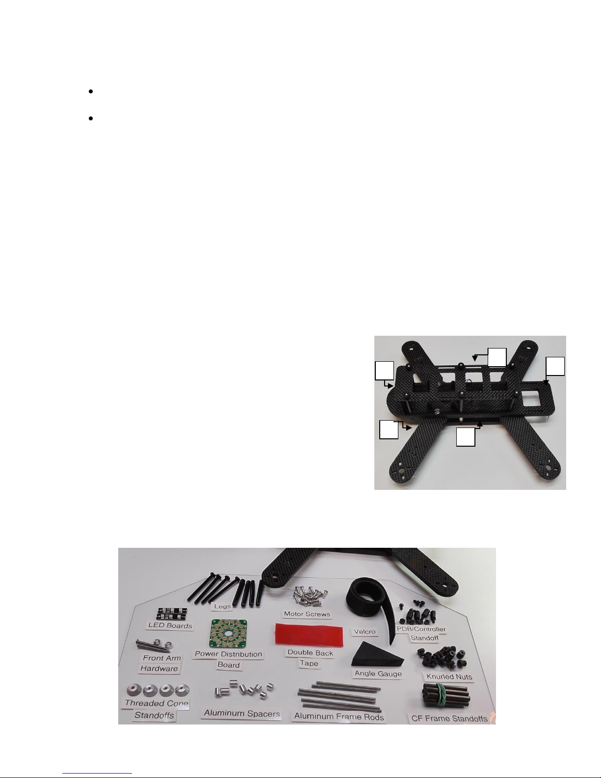
Completed X4MR Airframe
Total Weight as
Pictured: 111 Grams
X4MR250 MexAir RC
2
oadditional space on certain surfaces of the frame when using embedded wiring
Top and bottom plate mounting using thru-layer tie-rods and fasteners creating a rigid structure
required by high power motor systems
Variable motor arm positioning that allows for
oFine adjustments to center of gravity
ovariable motor placement to enhance maneuverability
omotor arm “swing away” deflection on a hard-hit thus reducing crash damage potential
The X4MR 250 kit includes all the frame components and fasteners necessary to construct a 250 class
racing quad using electronics of your choice. You will receive the airframe in an already assembled state.
We have done this for you so that you can see how the frame should look when completely assembled.
It is expected that you will disassemble some of it during the build. The instructions that follow assume
that you simply received the kit in a completely disassembled state.
The airframe comes configured to mount the supplied Power Distribution Board with the included PDB
standoffs and predrilled main frame mounting holes. This PDB mount allows for “piggy-back” mounting
of a 30.5mm controller board using additional standoffs. The frame body already has embedded wire
leads to solder the included LEDs to both the front and rear to assist in visual orientation during flight.
The motor arms have internal wire cavities that allow for embedding the motor wires up to the main
frame and the speed control bottom plate.
X4MR Kit Contents: (See Accompanying Pictures)
1. Main Frame Body w/preinstalled LED wiring
2. Motor Arms (4)
3. Top Plate [To mount FPV Gear]
4. Bottom Plate [To mount ESCs]
5. Camera Plate [To mount forward looking camera]
6. Landing Gear Legs, Boots, and Mounting Hardware (4 sets)
7. Power Distribution Board [3oz copper PDB for higher
current applications]
8. LED Boards, 4S LiPo Capable (Front & Rear)
9. PDB Mounting Standoff Set
10. Plate Mounting Standoffs/Hardware Set
11. “Hook & Loop” Battery Strapping Material
12. Alternate 3mm motor mounting screws (16) if your motor screws will not fit properly
13. Double Backed Insulating Tape
1
2
3
4
5

X4MR250 MexAir RC
3
Other “stuff”typically installed on a racing multirotor frame includes:
Flight Controller Board
Motors
Propellers
Speed Controls (ESCs)
FPV Gear and cameras
Batteries and Battery Connectors
In some frame designs, including the X4MR, there are varying options for positioning and mounting
components. We listed options for those that have shown to be useful and tested successfully with the
X4MRs we build in-house.
Recommended Options:
Voltage Regulator(s)
oNote: If you do not have 5V and/or 12V supplies that may be necessary for your camera
systems, these can be handy add-ons wired direct to the supplied PDB.
Satellite receiver vs. standard receiver?
oTesting with a Spektrum satellite receiver showed no adverse effects on range or signal
reception. It is a good lightweight alternative to traditional receivers due to small size
and less wiring as might otherwise be necessary. It can be mounted almost anywhere
on the X4MR airframe.
General Guidance to make assembly faster, easier and safer:
1. Read through the assembly instructions completely PRIOR to beginning construction.
2. Inventory all kit supplied parts, your electronics and tools, organizing them according to your
intended build. Do not forget about any general supplies such as solder, heat shrink, small tools,
etc.
3. Use small amounts of blue loctite thread locker on all metal-to-metal screw contact surfaces,
especially motor mounting screws.
4. “Dry-fit” and test all electronics and FPV gear, to the extent possible during the build, so
disassembly will not be required after you have completed the frame assembly.
5. Pre-plan purchase of motors that have sufficient motor wire length and diameter to allow for
embedding the wires into the motor arms. The minimum length of the leads should be 4 inches.
The wire diameter, including insulation, should be a maximum of 1/16” (~20 gauge) to fit into
the arm holes. If larger, the holes can be widened as described in this manual. Alternately, any
wire length or diameter can be used by surface mounting them.
6. Take care in soldering components to prevent shorting between solder pads or overheating any
sensitive electronic components.
7. Although the skills, techniques, and “hazards” associated with this build are typical for many
hobby related activities, we always strive for safe and efficient construction techniques. We
therefore repeat here what you have likely learned from your previous experiences:
a. The X4MR airframe kit does not require any drilling for the typical build. If drilling
holes in the carbon fiber (CF) for self tapping screws or larger component attachments
use a sharp drill bit and work with light pressure and a relatively high speed drill. CF can
not be “punch marked” for drilling. A small electric rotary tool or drill press is
recommended to prevent the bit from “wandering” as you start the hole. Wear
appropriate safety gear, including air mask/filter, if creating carbon dust.

X4MR250 MexAir RC
4
b. Always wear appropriate safely gear or take other precautions during any operation
that could create a hazardous condition –including soldering, drilling, cutting and
grinding.
8. Carbon fiber is a conductive material. Never allow bare battery terminals or other
powered connections to physically come into contact with the carbon fiber or metal
components of the frame. Contact may create short circuits that may damage
electrical components and/or become a fire hazard. Always insulate powered
terminals from the frame using nonconductive materials such as electrical insulating
tape, heat shrink tubing, or plastic/nylon standoffs or mounts.
9. NEVER attempt to screw any component into the carbon fiber frame without first
carefully drilling the appropriately sized hole at the fastener location. Self tapping
screw/bolt hole sizes are slightly larger than the inner diameter of the threaded
portion of the fastener. When tightening a self tapping fastener, it may be necessary
to start tightening it, back it out slightly, repeating this process until the fastener is
threaded to the proper depth. This creates a threaded hole that should hold firmly
without any other aid. For added assurance, use the time-tested technique of
“hardening” the laminate core material AFTER you create the threads using the self
tapping fastener. Remove the fastener from the hole and carefully drip 2 –3 small
drops of thin CA into the hole. The CA will “wick” into the core thread area and harden
the core material. Allow sufficient time (usually only a couple of minutes) for the CA to
completely dry prior to reinserting the fastener. You do not want to glue the fastener
permanently in the hole! Hardening the laminate core material, although not typically
necessary, is only done if you intend to insert a threaded fastener that will be
tightened across the laminated surfaces causing significant compressive forces on the
laminate structure. Hardening reduces “dimpling” the surface when compressed. The
laminate structure is sufficiently strong and some dimpling is not a bad thing –it
actually acts to further reduce the possibility of fasteners loosening. Excessive
tightening is unnecessary.
X4MR250 MexAir RC
5
Construction of the X4MR Airframe
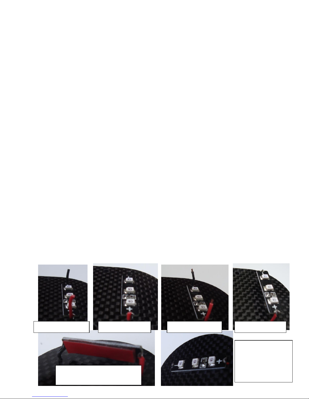
1. LEDs (LED Boards supplied with this kit can be run direct to 4S LiPo power without any
voltage regulator)
a. The preinstalled LED power leads feed through the body of the frame and exit the
frame conveniently below the PDB position. Do not permanently connect the power
side of the leads to the PDB or power source at this time. Permanent installation
should be done after final placement of the PDB, any necessary voltage regulators,
and speed controls.
b. Place the main frame body upside down. First, gently push the LED wires a slight
amount into the wire exit hole and then pull gently to see how much slack wire you
have to work with. Note the slack amount. Strip the remaining insulation leaving the
amount of insulation you determined as slack.
c. Cut the excess bare wire leaving about ¼” bare. Tin the bare end.
d. If your kit was supplied with single color wires, trace the wire from the LED location
to the planned source end with an ohm-meter. Mark both the positive (+) and
negative (-) wire ends at the main body hole (the large elongated hole). You can
always trace the polarity later during the build if you forget to do it now. If supplied
with colored wires, the red (or white) wire will always be intended as the positive (+).
The other wire is the negative (-).
e. Solder the LED board to the wires paying attention to the proper polarity. Measure
and cut a small strip of supplied double backed tape the same size as the LED board.
[This is very sticky stuff! You may want to handle it with the tip of a small hobby
knife blade rather than your fingers.] Apply the sticky side between the wire holes
on the body underside. Remove the remaining tape backing.
f. At this time you should be able to push the soldered wires of the assembly slightly
into the body so the board will lay flat to the tape. Readjust as necessary.
g. Verify that the bare metal of your solder joint is not touching the carbon frame body
and the board is fully insulated from the body by the tape.
Wires Fully Extended
Partially into Body
Insulation Stripped
Soldered to Board
Double Backed Tape Applied to
Bottom of Board or Frame
Tape Backing
Removed, wires
pushed into holes &
LEDs Pressed Into
Place


