Meya CLOU 9.500 User manual
GB
We move people.
OPERATING MANUAL
CLOU, MODEL 9.500

2
Contents
Foreword ....................................................................................................... 7
Acceptance .................................................................................................... 8
Adjustment ................................................................................................... 8
Specifications................................................................................................ 8
Use ................................................................................................................. 8
Overview ....................................................................................................... 9
Model: 9.500 .........................................................................................................9
Driving......................................................................................................... 10
Functional checks ...............................................................................................10
Tips for accident prevention..............................................................................10
Emergency off ...............................................................................................10
Brakes .......................................................................................................... 11
Service brake.......................................................................................................11
Braking the wheelchair ................................................................................11
Parking brake .....................................................................................................11
Selection lever ....................................................................................................12
Locking the brake .........................................................................................12
Releasing the brake ......................................................................................12
Drive-/push mode ...............................................................................................13
Selecting the push mode..............................................................................13
Selecting the motor mode ...........................................................................13
Selecting the operation ............................................................................. 14
Pre-operation checks..........................................................................................15
Charging procedure......................................................................................16
Positioning the operating module....................................................................17
Function description .....................................................................................17
Horizontal adjustment..................................................................................17
Vertical adjustment.......................................................................................17
Remove the operating module....................................................................17
Fitting of the operating module..................................................................17
Turning the operating module to the side .................................................18

3
Folding/Unfolding....................................................................................... 19
Folding the wheelchair.................................................................................19
Unfolding the wheelchair ............................................................................22
Loading and transportation ...................................................................... 25
Transport in vehicles .....................................................................................25
Loading ..........................................................................................................25
Transport security..........................................................................................26
Safety information........................................................................................26
Arm supports .............................................................................................. 27
Remove the arm support..............................................................................27
Inserting the arm support ............................................................................27
Adjusting the height of the arm supports..................................................28
Adjusting the clothes guard.........................................................................28
Height stopper (Memory effect)..................................................................29
Depth adjustment of the arm support cushions ........................................29
Back support ............................................................................................... 30
Standard back support .................................................................................30
Detaching the standard back support.........................................................30
Attaching the standard back support .........................................................30
Adjustable back.............................................................................................31
Adjusting the angle of the back support....................................................33
Seat .............................................................................................................. 34
Seat cushion...................................................................................................34
Removing the seat strap...............................................................................34
Inserting the seat ..........................................................................................34
Adjustable seat strap ....................................................................................34
Adjustment of seat width ............................................................................35

4
Leg supports ............................................................................................... 36
Calf strap........................................................................................................36
Folding up the footplates ............................................................................37
Turning the leg supports to the side ..........................................................37
Swivelling in the leg supports .....................................................................37
Remove the leg supports..............................................................................38
Attaching the leg supports ..........................................................................38
Adjusting the height of the footplate ........................................................39
Adjusting the angle-adjustable foot plate .................................................39
Height-adjustable leg supports 774 AL ............................................................40
Removing the height adjustable leg supports ...........................................40
Attaching the height adjustable leg supports............................................40
Adjusting the height of the footplate ........................................................40
Lifting the height adjustable leg supports .................................................41
Lowering the height adjustable leg supports ............................................41
Adjusting the depth of the calf pads ..........................................................42
Adjusting the height of the calf pads .........................................................42
Stump support ....................................................................................................42
Swivelling away / removing the leg stump support...................................42
Attaching the leg stump support ................................................................43
Adjusting the height of the stump support ...............................................43
Positioning the calf plate .............................................................................43
Stick-in support wheels ............................................................................. 44
Inserting / removing the anti-tip castors.....................................................44
Inserting the anti-tip castors ........................................................................44
Seat belt ...................................................................................................... 45
Fastening the seatbelt with buckle .............................................................46
Fastening the seatbelt with velcro strap.....................................................46
Adjustment of belt length ...........................................................................46
Walking aid holder ..................................................................................... 47

5
Step climber................................................................................................ 48
Crossing an obstacle .....................................................................................48
Detaching the step climber ..........................................................................49
Attaching the step climber...........................................................................49
Attendant control with priority switch ................................................... 50
Positioning the controller.............................................................................50
Lighting ....................................................................................................... 51
Rear-view mirror......................................................................................... 51
Removing the rear-view mirror ...................................................................51
Attaching the rear-view mirror....................................................................51
Adjusting the rear-view mirror ....................................................................51
Service ......................................................................................................... 52
Maintenance.......................................................................................................52
Inspection............................................................................................................52
Maintenance instructions.............................................................................53
List of annual maintenance work................................................................55
Fault correction .............................................................................................56
Battery charger...................................................................................................57
Wheel change.....................................................................................................58
Disassembly of the drive wheels..................................................................58
Assembly of the drive wheels ......................................................................58
Disassembly of the steering wheels.............................................................59
Assembly of the steering wheels .................................................................59
Fuses ....................................................................................................................60
Replacing the fuses .......................................................................................60
Lighting ...............................................................................................................61
Adjusting the headlights..............................................................................61
Headlights......................................................................................................62
Front indicator...............................................................................................63
Rear indicator ................................................................................................64
Back light .......................................................................................................65

6
Information for the dealer ................................................................................66
Programming the driving behaviour...........................................................66
Driving parameter.........................................................................................67
Standard programming................................................................................67
Technical data ............................................................................................. 68
Kilometric performance.....................................................................................68
Hill climbing ability .......................................................................................68
Fuses ....................................................................................................................69
Lighting ...............................................................................................................69
Tools.....................................................................................................................70
Tightening torque for screwed connections....................................................70
Model 9.500 ........................................................................................................71
Meaning of the labels on the wheelchair ........................................................75
Inspection certificate..........................................................................................76
Guarantee ................................................................................................... 78

7
FOREWORD
We thank you for the confidence you
have placed in our company by choos-
ing an electric wheelchair from this
series.
The electric wheelchair can be adapt-
ed to your individual needs by way of
the equipment variants and the acces-
sories.
Like any other vehicle, the electric
wheelchair is a technical aid. It is sub-
ject to explanations, requires regular
care and can cause danger when used
improperly. The correct handling must
therefore be learned.
This manual is to help you get accus-
tomed to the handling of the electric
wheelchair as well as to prevent acci-
dents.
☞Note:
Please note that the illustrated
equipment variants can deviate
from your model.
!Attention:
Read and observe the following
documentation belonging to the
electric wheelchair before first
use:
– this operating manual,
– the operating manual < Operating
modules VR2 >.
– the safety and general handling in-
structions < Electronic vehicles >.
☞Note:
Children should read the docu-
mentation belonging to the elec-
tric wheelchair together with their
parents respectively a supervisor or
attendant before first use.

8
ACCEPTANCE
All products are checked for faults
in the factory and packed in special
boxes.
☞Note:
However, we request that you
check the vehicle for possible
transport damage immediately on
receipt – preferably in the presence
of the carrier.
☞Note:
The packaging of the electric
wheelchair should be stored for a
further transport that might be-
come necessary.
ADJUSTMENT
The specialist workshop will hand out
the electric wheelchair to you under
consideration of all relevant safety
instructions, ready for operation and
adjusted to your needs.
☞Note:
The tools required for adjustments
and maintenance is listed under
chapter < Technical Data >.
SPECIFICATIONS
The electric wheelchair is an environ-
ment-friendly electric vehicle. It was
developed to extend the mobility of
persons with health-related or age-re-
lated restrictions.
USE
The electric wheelchair, with attached
leg supports and arm supports, serves
exclusively for the conveyance of one
sitting person. Other pulling or trans-
porting uses do not comply with its
intended purpose.
This model is an electric wheelchair
especially for outdoor use on firm sur-
faces.
12
3
4
5
6
7
8
9
1011
12
9
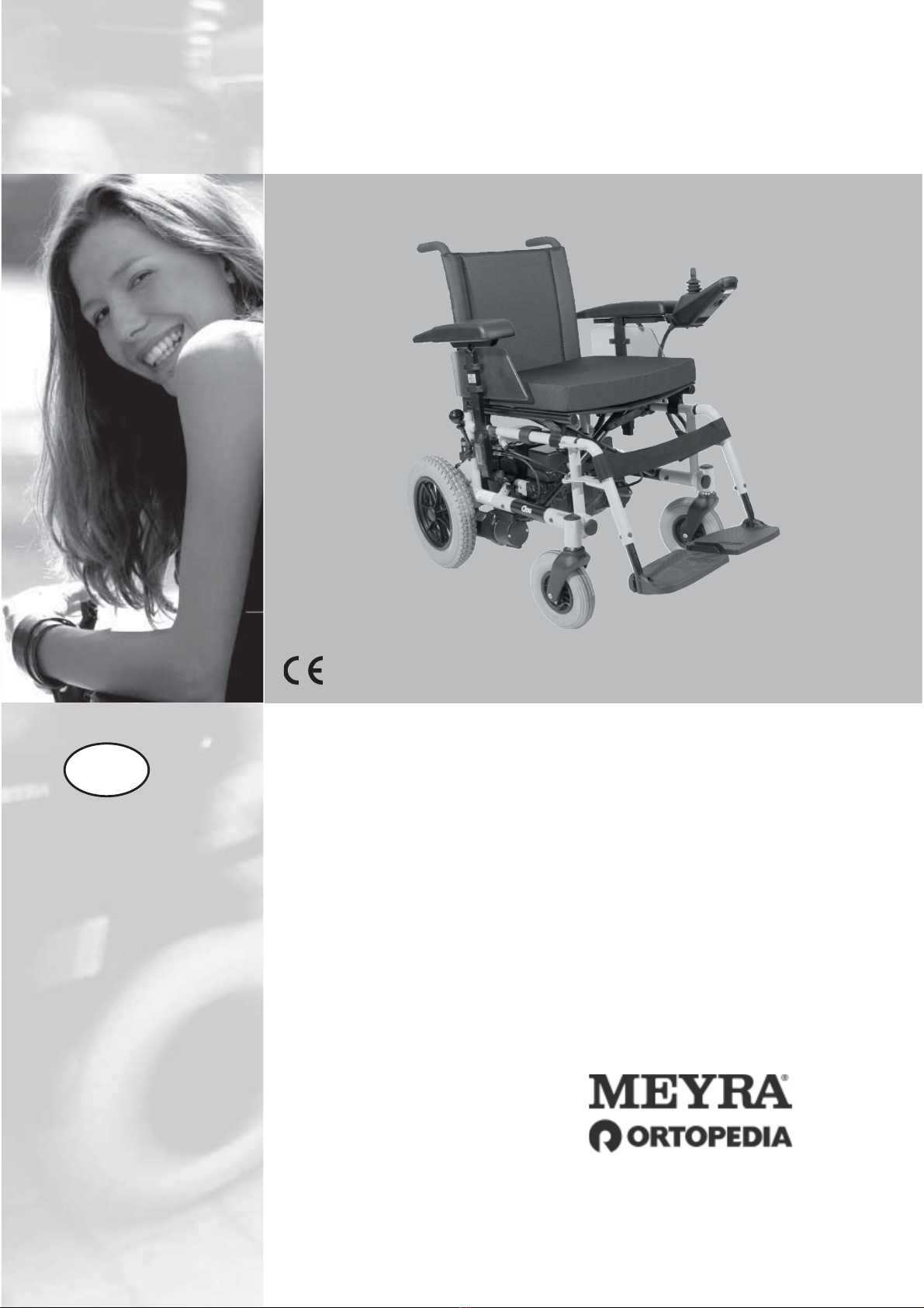
OVERVIEW
Model: 9.500
The overview shows the most important components and operating devices of
the electric wheelchair.
Push modeDrive mode
Pos. Description
1 Back support
2 Operating module
3 Seat cushion
4 Leg support
5 Footplate
6 Calf strap
7 Selection lever drive-/push mode
8 Arm support
9 Steering wheel
10 Drive wheel
11 Support castor
12 Push bar

10
DRIVING
Optimising the driving behaviour of
the electronic wheelchair with the
personal circumstances is to be co-or-
dinated by our service technician and
your specialist dealer or therapist.
The adaptability offers sufficient driv-
ing comfort as well as a high operat-
ing safety.
You define the speed and direction
yourself with the joystick movements
(driving and steering lever) while driv-
ing as well as the pre-adjusted maxi-
mum final speed of your electronic
wheelchair.
Functional checks
The functions and safety of the elec-
tric wheelchair must be checked be-
fore the start of each journey.
☞For this observe chapter < Inspec-
tions before starting to drive > in
the Operating manual of the Op-
erating modules VR2.
Tips for accident prevention
Emergency off
!Attention:
Only in case of uncontrolled driv-
ing behaviour of the vehicle
should you bring it to a still stand
by switching it off.

11
BRAKES
•Observe the safety and general
handling instructions < Electronic
vehicles >!
Service brake
The motors work electrically as oper-
ating brake and carefully brake the
electronic wheelchair down without
jerks to stillstand.
Braking the wheelchair
For allotted braking of the wheelchair
slowly guide the joystick back to the
centre position (zero-setting).
☞The wheelchair stops in shortest
distance after releasing the joy-
sticks.
Parking brake
The parking brakes only work when
the selection lever is in the drive
mode position. They disengage auto-
matically when the wheelchair starts
off. They are disengaged manually by
moving the selection lever to the push
mode position.
☞Therefore observe chapter < Drive/
push mode >.
3
1
2
12
Selection lever
Locking the brake
Swivel the selection lever forward as
far as possible (1).
!Attention:
It is impossible to push the electric
wheelchair when in drive mode.
•The brake performance reduces
with
the brake pads are worn.
If the electric wheelchair demonstrates
an uneven or impaired braking effect,
take it immediately to your specialist
workshop for repair.
Releasing the brake
Activate the locking sleeve (2) on the
selection lever and swivel the selec-
tion lever back as far as possible (3).
!Attention:
Only transfer to and from the elec-
tric wheelchair when the wheel-
chair is switched off and the selec-
tion lever has been placed into the
"drive" position!
•An unintentional movement of
the joysticks (driving and steering
lever) can otherwise lead to an un-
controlled start of the electronic
wheelchair! – Danger of accidents!

3
2
1
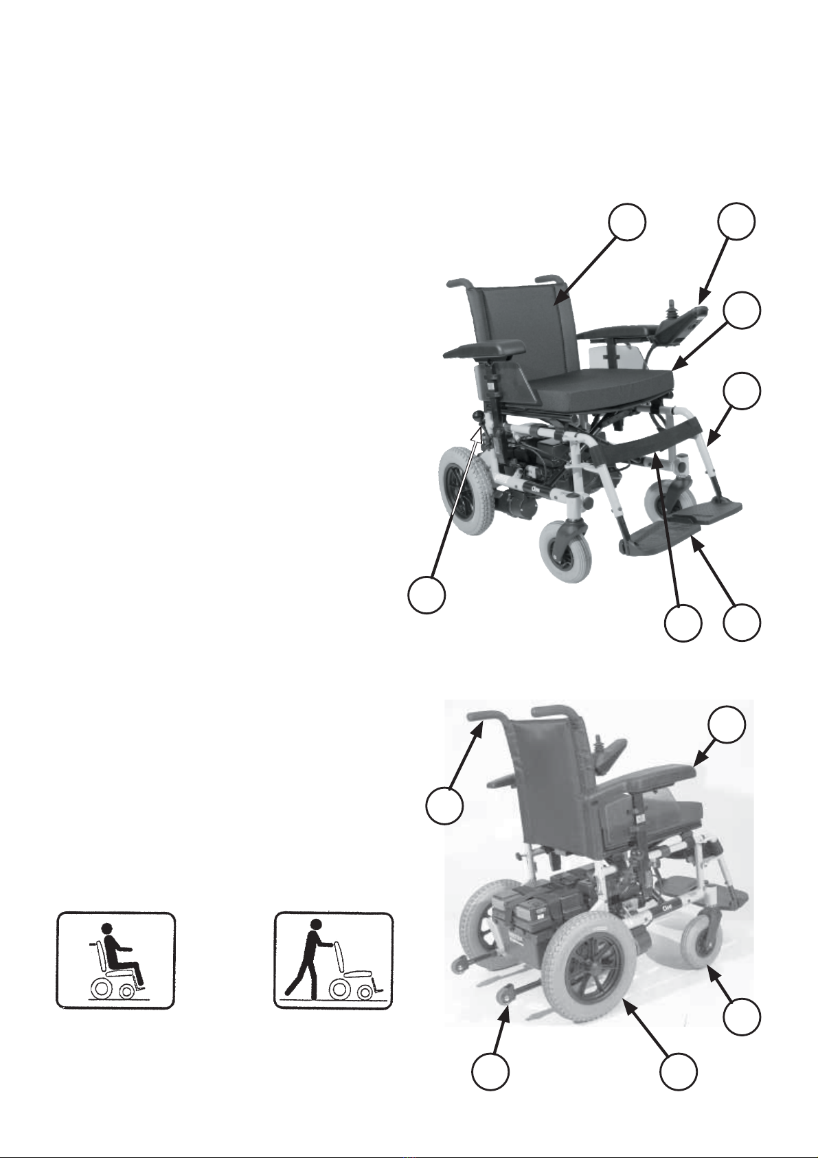
13
Drive-/push mode
The lever (1) for switching the drive
motors between the drive mode and
push mode is located on the right side
of the electric wheelchair.
!Attention:
Push the electric wheelchair only
for manoeuvring or in emergency
cases but never on gradients.
The electric magnetic brakes are
switched off in the push mode. A
braking of the wheelchair is then
only possible by switching to the
drive mode. Therefore do not
switch to the push mode on gradi-
ents.
Selecting the push mode
First switch off the operating module
because the pushing will otherwise be
made difficult by the electric system.
Afterwards activate the locking sleeve
(2) on the selection lever and swivel
the selection lever back as far as pos-
sible (3).
!Attention:
Do not switch the selection lever to
push mode while driving!
Selecting the motor mode
1. Push the selection lever to the front
(1) until it audibly latches.
2. Switching the operating module
on.
☞The electric wheelchair is now
ready for operation again.

1
2
3
14
SELECTING THE OPERA-
TION
In order to obtain operational readi-
ness of the electronic wheelchair the
following directions are to be carried
out in the indicated order.
☞Note:
Charge the drive batteries via the
operating module before the first
journey.
1. Shift to drive mode
Move the drive motors to the drive
mode position. Push the selection
lever to the front (1) until it audibly
latches.
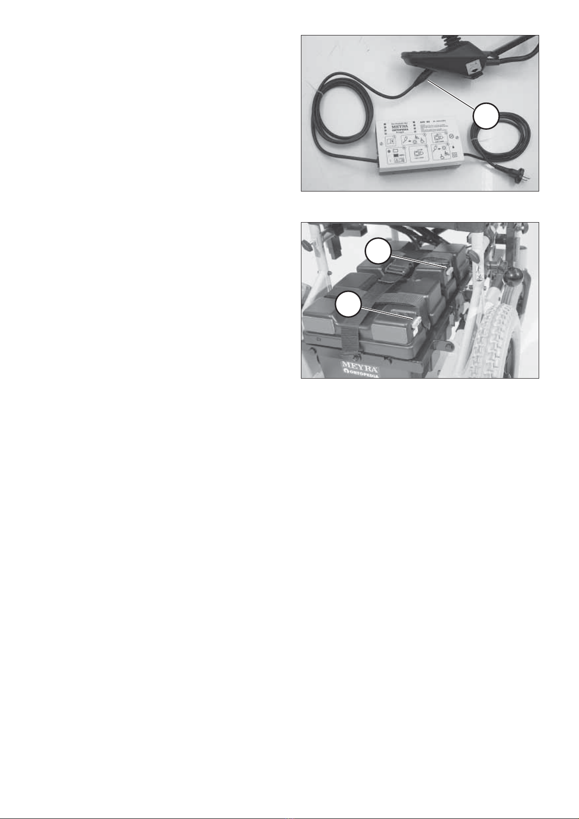
2. Check the tight seat of the bat-
tery fuse
Blade-type fuse:
The flat fuses (2) for the battery cur-
rent must sit securely in the fuse hold-
ers of the respective battery cover (3).
4
3
15
3. Checking the position of the
operating module
The operating module (3) should be
positioned in such a way that you can
comfortably and safely steer the elec-
tric wheelchair.
☞Therefore observe chapter < Posi-
tioning the operating module >.
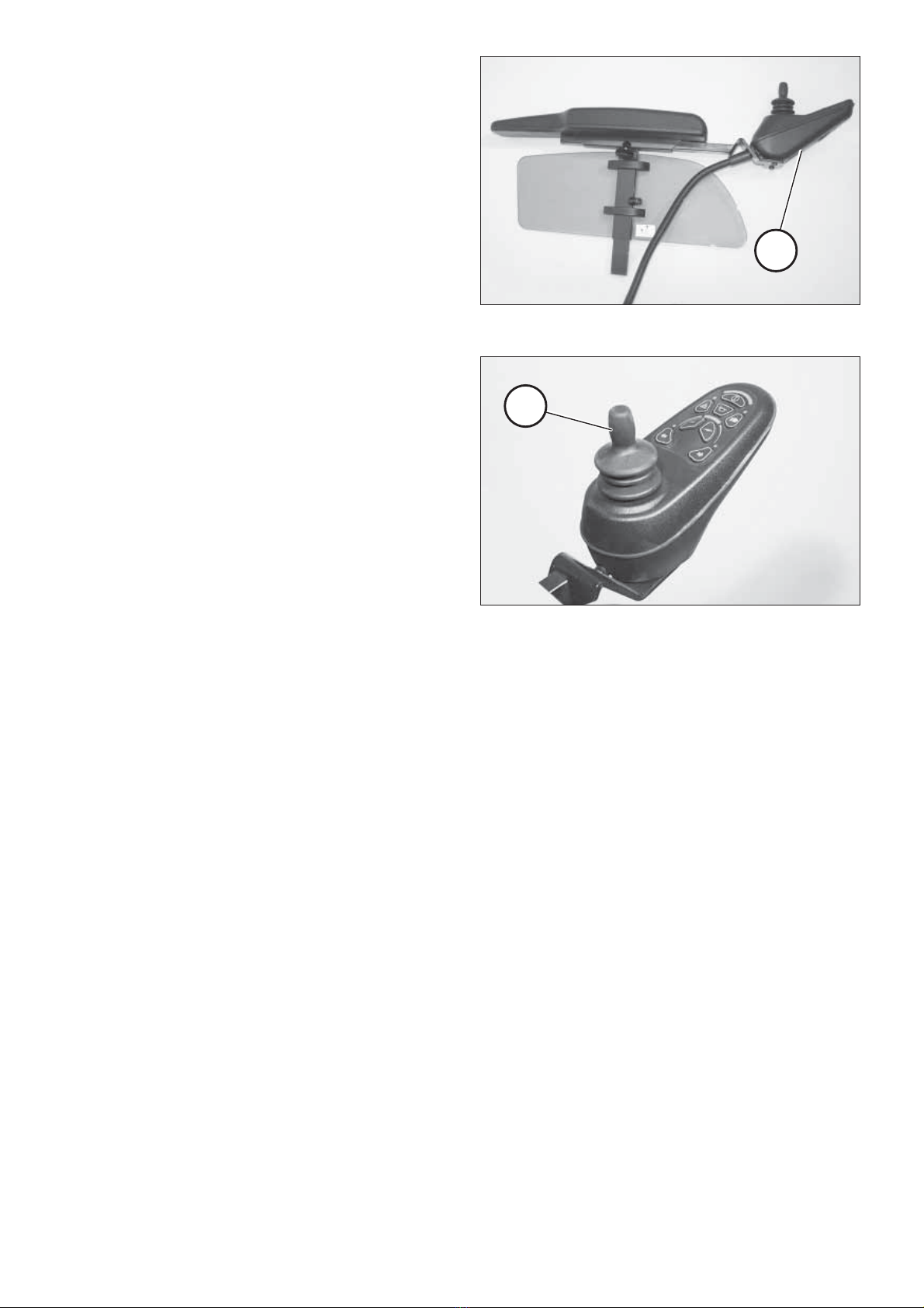
4. Switching the operating mod-
ule on
Press the ON/OFF-key on the key field
of the control panel.
☞Note:
Only actuate the joystick (4) after
the self-test of the electronics has
been completed!
☞Key-lock function:
☞The key-lock function enables you
to secure the wheelchair against
unauthorised use.
☞Observe user manual < Operating
module VR2 >, chapter < Key func-
tion >.
Pre-operation checks
Before starting to drive, the following
should be checked:
☞the battery charge level,
☞the pre-selected top speed setting.
– For this observe the operating
manual < Operating modules VR2
>.
1
2
2
16
Charging procedure
1. Switch the operating module off.
The selection lever should be in the
drive mode position.
2. Insert the battery charger plug into
the operating module (1).
!Attention:
Do not insert any objects other
than the battery charger plug into
the battery charging socket. – Dan-
ger of short circuit!
3. Switch on the battery charger, re-
spectively, plug the mains plug of
the battery charger into a conven-
ient mains socket. The battery is
now charging.
☞The charging procedure will only
run with intact battery fuses (2).
A full charging of the drive batteries
takes approximately 8 hours.
4. Disconnect the battery charger
from the mains socket at the end
of the charging process and then
pull the charging plug out of the
operating module.

12
17
Positioning the operating
module
Function description
You will find a detailed description of
the keys and symbols in the operating
manual for < Operating module >.
The position of the operating module
can be adjusted to suit the individual
size of the user. The control unit can
also be detached for transportation or
storage and can be laid on the seat or
stored separately.
!Attention:
Switch off the operating module
before adjusting/removing it.
Horizontal adjustment
Slacken the clamping screw for depth
adjustment (1). Move the operating
module into the desired position. In
doing so carefully guide the cable and
retighten the clamping screw secure-
ly.
Vertical adjustment
With the optional height adjustable
operating module adapter the op-
erating module can be adjusted in
height.
Slacken the clamping lever (2) whilst
holding the control unit, move the op-
erating module into the desired posi-
tion and then retighten the clamping
lever.
Remove the operating module
To remove the control unit, slacken
the clamping screw (1). Pull the oper-
ating module to the front.
☞Carefully route the cable when do-
ing this.
Fitting of the operating module
Insert the operating module into its
clamping device. Tighten the clamp-
ing screw (1).
☞Carefully route the cable when do-
ing this.
2
1
3
3
18
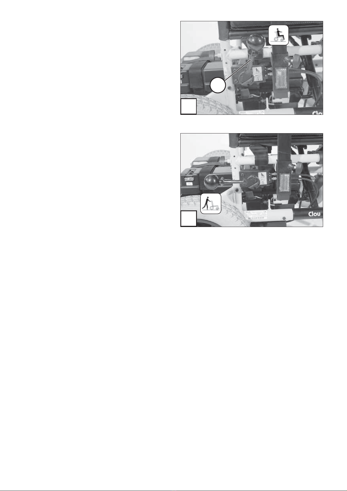
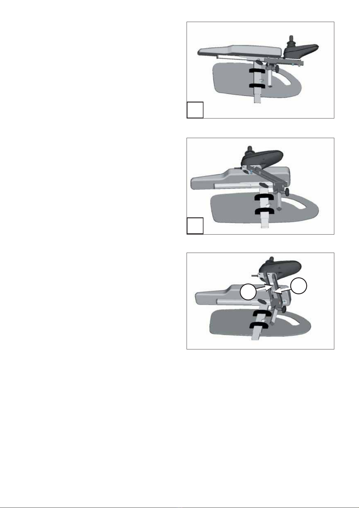
Turning the operating module to
the side
With the optional swivel away operat-
ing module adapter (1) the operating
module can be swivelled back to the
side (2) so that it is located parallel to
the arm support. This makes it possi-
ble, for example:
– to drive closer to a table,
– Remove the operating module
more easily.
For regular drive mode the operating
module can be swivelled back toward
the front (1) until it engages back into
the magnetic lock.
☞Note:
☞The power of the magnets (3) can
be reduced, for example with tape
on top of the magnets, for easier
swivelling of the operating mod-
ule.
☞Should the operating module be
positioned too close to the arm
support, move it forward before
swivelling.
!Attention:
Do not grab into the area of the
cross brace. – Danger of squash-
ing!
1
2
3
19
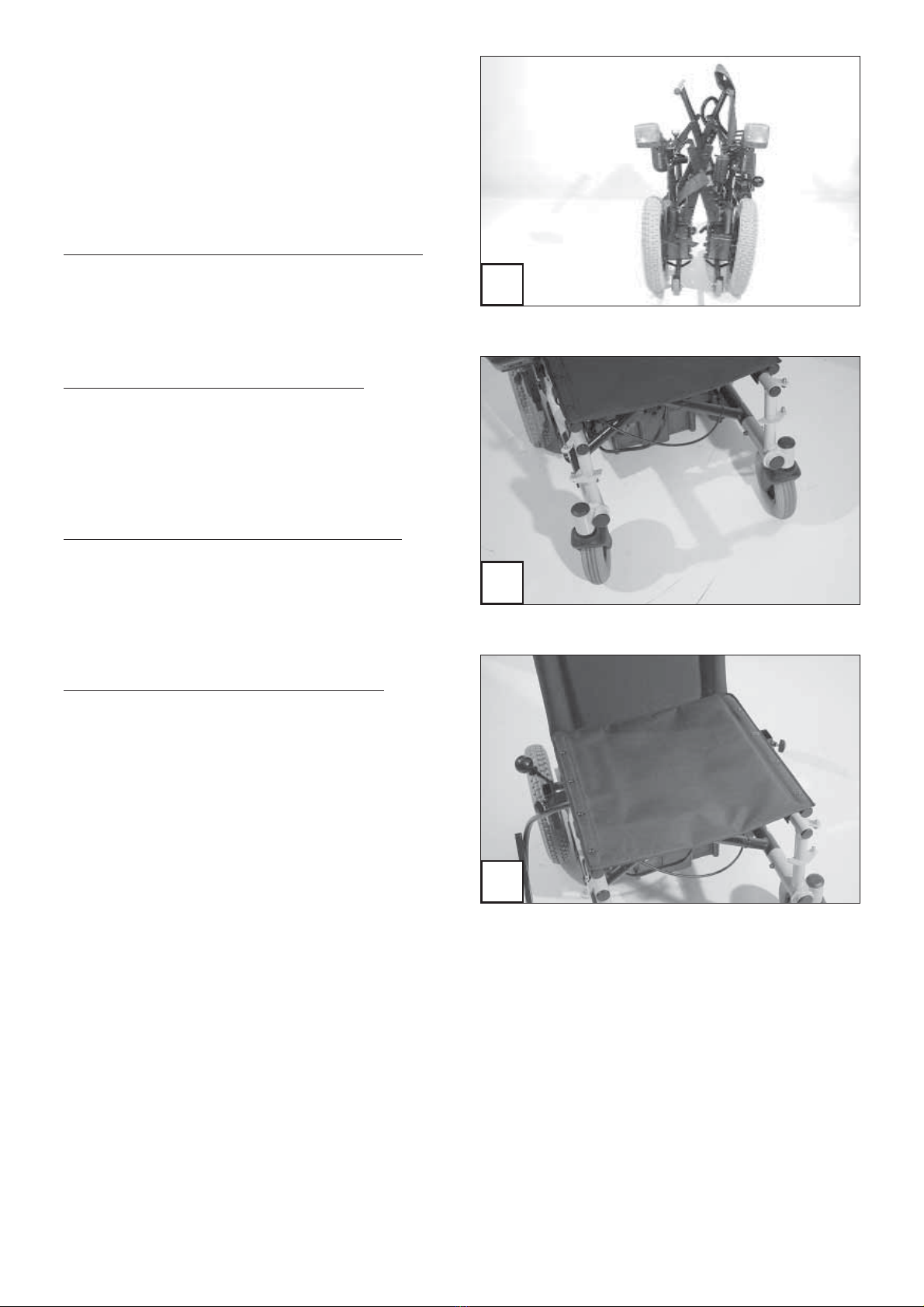
FOLDING/UNFOLDING
The electronic wheelchair is also col-
lapsible for car transportation (1).
Folding the wheelchair
1. Switch the operating module off
– Press the ON/OFF key.
☞Therefore observe operation man-
ual < Operating modules VR2 >.
2. Lift off the leg supports (2)
(only necessary if there is insuffi-
cient space)
☞Therefore observe chapter < leg
supports >.
3. Remove the operating module
(only necessary if there is insuffi-
cient space)
☞Therefore observe chapter < Posi-
tioning the operating module >.
4. Remove the arm supports (3)
(only necessary if there is insuffi-
cient space)
☞Therefore observe chapter < arm
supports >.

4
5
6
7
20
5. Remove the back support (4)
(only necessary if there is insuffi-
cient space)
☞Therefore observe chapter < back
support >.
6. Unhook the seat strap (5)
☞Therefore observe chapter < Seat
>.
7. Lift out the battery (7)
– Open the retaining straps by push-
ing together the springs of the
snap-catch (6).
– Then lift out the batteries with
their carrying strap and place them
carefully to one side (7).
Table of contents
Popular Wheelchair manuals by other brands


Drive DeVilbiss Healthcare
Drive DeVilbiss Healthcare XS2 Instructions for use

Stealth Products
Stealth Products UniLink Ultra owner's manual

Sunrise Medical
Sunrise Medical Quickie P-220 User instruction manual & warranty

Medline
Medline MDS808200SLRR Series Owner's & maintenance guide

Invacare
Invacare Nutron Series operating & maintenance manual

Moretti
Moretti MOPEDIA RC325-40 instruction manual


