manuals.online logo
Brands
  1. Home
  2. •
  3. Brands
  4. •
  5. Meyer
  6. •
  7. Outdoor Light
  8. •
  9. Meyer Fluxa C 8 277 1.8 User manual

Meyer Fluxa C 8 277 1.8 User manual

Projecteur pour lampes iodures métalliques
(HI), sodium haute pression (HS) 400 watts,
douille E40.
INSTRUCTION DE MONTAGE
Effectuer les branchements du projecteur
conformément aux normes en vigueur dans
votre pays. Le projecteur est prévu pour des
installations en extérieur non protégées.
Le projecteur convient au montage sur
des matériaux de construction normalement
inflammables.
Attention…! Haute Tension !
Bien faire attention à la dimension du mât,
si besoin prendre contact avec le fabricant
de mât. Dévisser les vis de fixation du cadre.
Soulever le cadre et le verre et le faire
basculer. Ouvrir le couvercle de
branchement. En fonction de la hauteur du
mât, faire entrer dans le presse étoupe une
longueur suffisante de câble d'alimentation,
dénuder le câble sur 16 cm et glisser les
enveloppes de silicone jointes sur chacun
des câbles.
Attention.. le câble avec l'enveloppe isolante
ne doit dépasser que de 2 cm maximum
dans le boîtier du projecteur. Les câbles ne
doivent pas être en contact avec le couvercle
de branchement. Puis procéder au
branchement électrique. Visser solidement la
vis du câble. Monter la lampe en prenant
garde qu'il s'agit bien du modèle
correspondant à l'étiquette. Pour les lampes
HS n'utiliser que celles portant l'indice .
Rabattre le cadre et le verre sur le corps du
projecteur et visser fermement.
Fixer le projecteur sur la fixation pour mât
par les vis M10 x 40 am et serrer à 44 Nm.
Faire glisser le câble par le trou de la fixation
pour mât et effectuer la connexion par le
boîtier de connexion situé dans le mât.
Montage sur mât
Avant d'ouvrir le projecteur ou de changer
la lampe, le déconnecter du réseau.
Area floodlight for metal halide (HI) or high
pressure sodium (HS) lamps 400 Watt,
lampholder E40.
MOUNTING INSTRUCTIONS
Connect the light fitting according to
VDE 0100 or in accordance with prevailing
regulations in your country.
Light fitting is suitable for installation on
normal inflammable building materials.
ATTENTION ! HIGH VOLTAGE !
Disconnect power supply before opening
light fitting or changing lamp.
Ensure that the correct size of pole is chosen;
if necessary consult the pole manufacturer.
Loosen screws in front frame. Lift frame and
glass and swing away from casing. Open
control gear cover. Depending on height of
pole, take a sufficiently long piece of cable
and insert it through the cable gland. Strip
the sheathing off the last 16 cm of cable and
slide the enclosed silicone sleeves over the
individual wires.
ATTENTION ! Do not insert more than 2 cm
of sheathed cable into luminaire housing:
Ensure that the wires do not make contact
with the control gear cover. Make the
electrical connection. Screw cable gland
tight. Close control gear cover. Insert lamp,
taking care to use the correct lamp as
mentioned on the rating plate. If a high
pressure sodium lamp is to be used, make
sure that only lamps bearing the - sign
are used. Swing front frame and glass back
onto casing and screw down evenly.
Mounting on pole top fitter
Hang the luminaire onto the M10 x 40
screws on the pole top fitter and tighten with
44 Nm torque. The threaded inserts in the
pole top fitter are self locking.
Push cable through hole in pole and
connect to connection box in base of pole.
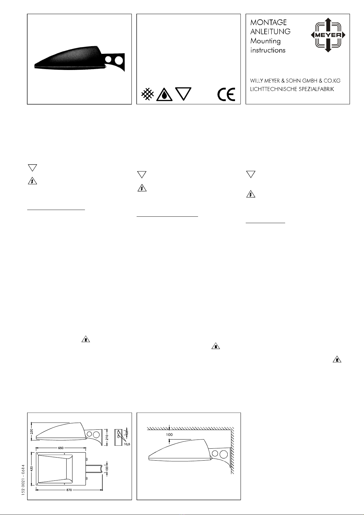
Luminaire for
non-protected outdoor installation.
Fluxa C - Ausleger
Flächenstrahler
Area floodlight
Schutzart - Protection IP 54
Schutzklasse - Safety Class I
Flächenstrahler für
Halogen-Metalldampflampen (HI),
Natriumdampf-Hochdrucklampen (HS)
400 Watt, Fassung E40.
MONTAGEHINWEISE
Anschluß der Leuchte nach VDE 0100.
Flächenstrahler für ungeschützte Anlagen.
Leuchte ist geeignet für Montage auf
normal entflammbaren Baustoffen.
Achtung Hochspannung !
Vor dem Öffnen der Leuchte oder
Lampenwechsel Netzspannung trennen.
Auf ausreichende Dimensionierung des
Mastes achten, ggf. Rücksprache mit dem
Masthersteller nehmen.
Rahmen-Befestigungsschrauben lösen.
Rahmen mit Glas anheben und vom
Gehäuse schwenken. Deckel der
Geräteabdeckung öffnen. Je nach Masthöhe
ausreichend lange Netzanschlußleitung
durch die Kabelverschraubung führen,
Leitung 16 cm abmanteln und beiliegende
Silikonschläuche über die Einzeladern ziehen.
ACHTUNG ! Mantelleitung darf maximal
2 cm in das Leuchtengehäuse ragen. Darauf
achten, daß die Einzeladern nicht an den
Abdeckblechen anliegen. Elektrischen
Anschluß vornehmen. Kabelverschraubung
festdrehen. Geräteabdeckung verschließen.
Lampe einsetzen, dabei auf richtige
Bestückung laut Typenschild achten. Bei HS-
Lampen nur solche mit - Kennzeichnung
einsetzen. Rahmen mit Glas auf Gehäuse
schwenken und dicht verschrauben.
Leuchte an die Schrauben M10 x 40 am
Mastaufsatz einhängen und mit einem
Drehmoment von 44 Nm anziehen.
Die Gewindeeinsätze im Mastaufsatz sind
selbstsichernd. Das Anschlußkabel durch die
Bohrung im Mastaufsatz schieben und am
Kabelübergangskasten im Mast anschließen.
Montage am Mastaufsatz
F
8 277 1.8
8 278 1.8
t 25°C
a
FF
.
Stemmessiepener Weg 5 D-58675 Hemer
F
Montage sur plaque murale
Montage sur autres surfaces
Bien faire attention à ce que la plaque
murale soit suffisamment fixée sur la surface
d'installation.
Fixer le projecteur sur la fixation pour mât
par les vis M10 x 40 am et serrer à 44 Nm.
Faire passer le câble dans l'appareil à travers
la vis de câble et faire les branchements
comme indiqué ci-dessus.
Faire attention à ce que la surface
d'installation soi suffisamment stable.
Utiliser au minimum 2 vis inoxydable
M10 x 40 résistance 70 pour fixer l'appareil.
Prendre toutes les précautions nécessaires
afin que les vis ne se desserrent pas.
Faire les branchements électriques selon les
spécifications ci-dessus mentionnées.
Le verre est un verre sécurit.
Le projecteur ne doit être utilisé qu'avec
toutes ses protections.
Article poids surface exposée au vent
8 277 1.8 23,2 kg 0,28 m²
8 278 1.8 23,2 kg 0,28 m²
Attention, respecter la distance minimum
nécessaire entre le projecteur et la surface à
éclairer.
Montage an der Wandplatte
Auf ausreichende Befestigung der
Wandplatte auf dem Montagegrund achten !
Leuchte an die entsprechenden Schrauben
M10 x 40 einhängen und die Schrauben mit
einem Drehmoment von 44 Nm anziehen.
Zuleitung durch die Kabelverschraubung in
die Leuchte einführen und wie zuvor
beschrieben anschließen.
Auf ausreichende Festigkeit des
Montagegrundes achten. Zur Befestigung
der Leuchte mind. zwei rostfreie Schrauben
M10 x 40 der Festigkeit 70 verwenden und
für einen ausreichenden Lockerungsschutz
sorgen. Elektrischen Anschluß wie zuvor
beschrieben vornehmen.
Montage auf anderen Oberflächen
Die Gewindeeinsätze in der Wandplatte sind
selbstsichernd.
Das Glas ist ein Einscheiben-Sicherheits-
Hartglas.
Die Leuchte darf nur mit ihren vollständigen
Schutzabdeckungen betrieben werden.
Leuchte Gewicht Windangriffsfläche
8 277 1.8 23,2 kg 0,28 m²
8 278 1.8 23,2 kg 0,28 m²
In Strahlrichtung den Mindestabstand zu
angestrahlten Flächen einhalten !
Mounting on the Wall Plate
Mounting on other surfaces
Make sure that the wall plate is sufficiently
securely fixed to the installation surface.
Hang the luminaire onto the M10 x 40
screws and tighten them with a torque of
44 Nm. The threaded inserts in the wall plate
are self locking. Insert the cable through the
cable gland into the luminaire and then
proceed with the electrical connection as
mentioned above.
Make sure that the installation surface is
sufficiently stable and strong. To attach the
luminaire, use at least 2 stainless steel
M10 x 40 screws of hardness 70.
Take adequate precautions to prevent the
screws from loosening. Make electrical
connection as mentioned above.
The glass is toughened safety glass.
The light fitting may be operated only if all
protective covers are in place.
Ensure that the minimum spacing between
luminaire and illuminated surface is
observed.
Type Weight Projected area
8 277 1.8 23,2 kg 0,28 m²
8 278 1.8 23,2 kg 0,28 m²
min 1,0 m min 1,0 m min 1,0 m

This manual suits for next models

5

Other Meyer Outdoor Light manuals

Meyer 8 610 4 Series User manual

Meyer

Meyer 8 610 4 Series User manual

Meyer 8 730 1 Series User manual

Meyer

Meyer 8 730 1 Series User manual

Meyer Fluxa BG LED User manual

Meyer

Meyer Fluxa BG LED User manual

Meyer Superlight LED 3 User manual

Meyer

Meyer Superlight LED 3 User manual

Meyer 8 707 0 Series User manual

Meyer

Meyer 8 707 0 Series User manual

Popular Outdoor Light manuals by other brands

Unilamp Mini AGAR Prismatic - Bollard installation manual

Unilamp

Unilamp Mini AGAR Prismatic - Bollard installation manual

Aspen 1900-OA installation instructions

Aspen

Aspen 1900-OA installation instructions

New Works Kizu ASSEMBLY  & CARE GUIDE

New Works

New Works Kizu ASSEMBLY & CARE GUIDE

HUDSON VALLEY LIGHTING TROY LIGHTING BURBANK P1321 installation instructions

HUDSON VALLEY LIGHTING

HUDSON VALLEY LIGHTING TROY LIGHTING BURBANK P1321 installation instructions

Hess LINEA 10.00200.4500 Installation and operating instructions

Hess

Hess LINEA 10.00200.4500 Installation and operating instructions

Quoizel LWS3200D manual

Quoizel

Quoizel LWS3200D manual

Regent 32W Large Inground Mite installation instructions

Regent

Regent 32W Large Inground Mite installation instructions

VIBIA Tempo Assembly instructions

VIBIA

VIBIA Tempo Assembly instructions

Park Harbor FOUNDATIONS Hidden Creek quick start guide

Park Harbor

Park Harbor FOUNDATIONS Hidden Creek quick start guide

WE-EF LTC440 Installation and maintenance instructions

WE-EF

WE-EF LTC440 Installation and maintenance instructions

LUMEN CENTER ITALIA ODILE LETTURA Assembly istructions

LUMEN CENTER ITALIA

LUMEN CENTER ITALIA ODILE LETTURA Assembly istructions

ET2 Alumilux E41328 manual

ET2

ET2 Alumilux E41328 manual

Clas Ohlson 36-1866 instruction manual

Clas Ohlson

Clas Ohlson 36-1866 instruction manual

JONATHAN Y JYL3083 instructions

JONATHAN Y

JONATHAN Y JYL3083 instructions

B-K lighting HP2 SERIES installation instructions

B-K lighting

B-K lighting HP2 SERIES installation instructions

Velleman ZL388/11 user manual

Velleman

Velleman ZL388/11 user manual

Signature Hardware PADDOCK manual

Signature Hardware

Signature Hardware PADDOCK manual

Home Accents Holiday TY219-1714-1 Assembly instructions

Home Accents Holiday

Home Accents Holiday TY219-1714-1 Assembly instructions

manuals.online logo
manuals.online logoBrands
  • About & Mission
  • Contact us
  • Privacy Policy
  • Terms and Conditions

Copyright 2025 Manuals.Online. All Rights Reserved.