Meyer 51200 Super V LD Instruction Manual

Form No. 1-1149
May 2016
EZ Crate Assembly and Installation
51200 Super V LD Plow with V-71 12V Hydraulic Unit
© 2016 Printed in the U.S.A.
Meyer Products LLC
18513 Euclid Ave. • Cleveland, Ohio 44112-1084
Phone 216-486-1313
www.meyerproducts.com• email [email protected]
Meyer Products LLC reserves the right, under its continuing product
improvement program, to change construction or design details,
specicationsandpriceswithoutnoticeorwithoutincurringanyobligation.

Table of Contents
General Information.........................................................................................................................................................................................................................1
Illustrated Parts Lists ....................................................................................................................................................................................................................2-4
Build Assembly...................................................................................................................................................................................................................................5
Vehicle Side Wiring Diagram.....................................................................................................................................................................................................6-7
Drop Speed Adjustment.................................................................................................................................................................................................................7
Stop Bolt Adjustment ......................................................................................................................................................................................................................7
Mount Plow System To Vehicle.....................................................................................................................................................................................................8
Dis-Mount Plow System From Vehicle .......................................................................................................................................................................................9
Pre-Delivery Inspection................................................................................................................................................................................................................ 10
Accessories ....................................................................................................................................................................................................................................... 11
Web Based Support
(1)
GENERAL INFORMATION
Always disconnect battery prior to installation.
SAFETY PRECAUTIONS should be used when Quik Lift® is in a RAISED position.
LOWER plow to the ground when vehicle is PARKED.
OVERHAUL and SERVICE information is covered on separate instructions.
Lift arm should be removed from vehicle if / when snowplow is removed.
Note:
1. Connect ground cable to negative side of battery for a solid connection to ground.
2. Route all cables away from moving engine parts, Manifolds, and sharp sheet metal.
3. For weather protection, coat all connections with Meyer Dielectric Grease Part No. 15632
4.
The vehicle must be equipped with a “Heavy Duty Battery” (70 Amp, Hr. Min.), 550 C.C.A. and “Alternator” (60 Amp. Min.) to obtain maximum performance.
5. Follow these instructions explicitly. Warranty does not apply to a Meyer product which has been negligently or improperly assembled or installed.
ADDITIONAL BATTERY CONNECTIONS
1. When attaching cables to battery with side post terminals, use M.P. Adaptor Part #21976.
2. Coat battery connections with battery terminal coating. Bolt Nut Size Gr. 2 Gr. 5 Gr. 8
1/4 - 20 4 - 5
5/16 - 18 9 - 11
3/8 - 16 17 - 20 26 - 29
7/16 - 14 42 - 46 60 - 66
1/2 -13 64 - 72 90 - 100
5/8 - 11 127 - 141 179 - 198
TORQUE CHART FOOT POUNDS
Please check the contents of your crate. Page 2 shows the assembled parts in the left hand column and the accessory box in the right hand column.
Page 3 is the diagram for the left hand column of page 2.
http://www.meyerproducts.com/
TechSupport/ServiceManualsandIn-
stallationInstructions.aspx
http://www.meyerproducts.com/
techsupport/EZtroubleshooter.aspx
http://www.meyerproducts.com/
TechSupport/OwnersManuals.aspx
http://www.youtube.com/playlist?list
=PLDE0602B305314D92&feature=e
dit_ok
Service Manuals EZ-Troubleshooter Owners Manual Mount/DismountVideos
Please visit our website to nd our most updated technical information.
Tool list for Plow assembly:
Pliers
1/2" socket
1/2" box wrench
9/16" box wrench
9/16" socket
3/4" box wrench
15/16" box wrench
15/16" deep well socket

Parts Diagram
Parts List
Parts indented are included in the carton, bag or assembly under which they are indented.
V-71 PKG
Item Part No. Qty. Description
15193 1 V-71 Hydraulic Carton 12V w/o Controller
1 05024 1 • Power Cable - 36”
2 05815 1 • Lift Ram 1.75 x 8”
3 07713 2 • Ram Assembly 1-1/4 x 12 DA
4 05756 1 •• Ram (1-1/4” x 12”) DA
5 22866 2 •• SAE Mx3/8 90 Degree Elbow
6 22884 1 •• Hose 1/4 x 33”
7 22886 1 •• Hose 3/8 x 22”
08202 1 • Plug Bracket Kit
8 19607 1 •• Plug Bracket
9 19609 1 •• Plate
10 20027 2 •• Bolt H 5/16-18 x 1 Gr. 2
11 20326 4 •• Lockwasher 5/16
12 20525 4 •• Finish Nut 5/16-18
13 22658 2 •• Bolt H 5/16-18 x 3 Gr. 2
08366 1 • Hardware Bag
14 15067 1 •• Breather
15 15634 1 •• Hydraulic Cover
16 20029 4 •• Bolt H 5/16-18 x 1-1/2” Gr. 2
17 20049 2 •• Bolt H 3/8-16 x 1” Gr. 2
18 20152 2 •• Bolt H 5/8 - 11 x 5” Gr. 5
19 20153 2 •• Bolt H 5/8 - 11 x 5-1/2” Gr. 5
20 20304 4 •• Locknut 5/16-18
21 20309 4 •• Locknut 5/8-11
22 20327 2 •• Lockwaher 3/8”
23 20357 2 •• Flatwasher 5/8”
24 21398 2 •• Self Tap Screw 1/4-14 x 3/4”
25 22153 1 •• Lockbolt 5/16 x 5/8
26 22866 1 •• SAE Mx3/8 90 Degree Elbow
27 22868 5 •• Straight Fitting SAE 3/8 x 3/8
28 13333 1 • V-71 Mounting Bracket
29 13852 1 • V-71 Hydraulic Unit 12V
30 15370 1 • Motor Solenoid
31 15633 1 • Cover Strap
32 22691S 1 • Truck Side Harness
33 22696 1 • Super V Plow Side Harness
34 22883 1 • Hose 1/4 x 22”
35 07550 1 • Nite Sabre II Kit
36 13207 1 • Pivot Pin Super V LD
37 13855 1 • A-frame Super V LD Plus
38 19365 1 • Lift Frame
V-71 PKG
Item Part No. Qty. Description
16620 1 • Hardware Carton
08815 1 •• Hardware Bag
39 20028 4 ••• Bolt H 5/16-18 x 1-1/4” Gr. 2
40 20146 1 ••• Bolt H 5/8 - 11 x 3-1/4” Gr. 5
41 20152 1 ••• Bolt H 5/8 - 11 x 5” Gr. 5
42 20153 1 ••• Bolt H 5/8 - 11 x 5-1/2” Gr. 5
43 20309 3 ••• Locknut 5/8-11
44 20326 4 ••• Lockwasher 5/16”
45 20331 2 ••• Lockwasher 5/8”
46 20406 2 ••• Cotter Pin 3/16 x 1-1/2”
47 20420 2 ••• Cotter Pin 1/4 x 2”
48 20525 4 ••• Finish Nut 5/16-18
49 22436 2 ••• Pin 1 x 3”
50 814000005 2 ••• Spring
51 8500003307001 2 ••• Bolt H 5/8-11 x 3 Full Thread
52 8501003013 4 ••• 5/8-11 Jam Nut
08260 1 •• Hardware Bag
53 13724 1 ••• Deector Brace
54 13209 2 ••• Backing Plate
55 20028 7 ••• Bolt H 5/16-18 x 1-1/4”
56 20095 1 ••• Bolt H 1/2-13 x 1-1/2”
57 20304 7 ••• Locknut 5/16-18
58 20307 2 ••• Locknut 1/2-13
59 20329 1 ••• Lockwasher 1/2”
60 20352 7 ••• Flatwasher 5/16”
61 21961 2 ••• Bolt C 1/2-13 x 2”
09917 1 •• Plow Marker Kit
62 08214 2 ••• Plow Marker
63 20027 4 ••• Bolt H 5/16-18 x 1 Gr.5
64 20304 4 ••• Locknut 5/16-18
65 20352 8 ••• Flatwasher 5/16”
66 11751 1 •• Light Bracket LH
67 11752 1 •• Light Bracket RH
68 11844 1 •• Receiver Tube Cap
69 11859 2 •• Blue Handle Pin
70 12536 1 •• Top Deector Super V
71 13208 1 •• Bottom Belt
72 19370 1 •• Clevis EZ Mount Plus
73 19592 1 •• Lift Arm
74 22245 1 •• Crankstand
51200 Super V LD Plow Package
(2)
Meyer Products LLC reserves the right, under its continuing product
improvement program, to change construction or design details,
specicationsandpriceswithoutnoticeorwithoutincurringanyobligation.

Specic Components
(3)
Super V Plow Package
72
66
67
69
68
74
73
38
50
40
41
42
43
46
39
51
52
45
44 48
43
43
47
49
52
29
15
2
34
4
6
75
14
31
16 17
19
20
21
22
26
28
67
5
4
5
5
18
18
19
21
27
27

Item 51200 Qty Description
SV 7.5 LD Moldboard Assembly
09329 1 R.H. & L.H. Wing
75 09328 1 • R.H. Wing
76 09327 1 • L.H. Wing
77 13200 2 •• Trip Edge Weld
78 22438 8 •• 1 X 2-1/2” Pin
79 22945 8 •• 1/4 x 1-1/2” Roll Pin
80 13205 2 •• T -Bar Weldment
81 12978 4 •• Trip Spring
82 20145 2 •• Bolt H 5/8-11 x 3” Gr. 5
83 20318 2 •• Locknut 5/8-11
84 20357 4 •• Flatwasher 5/8
85 09124 4 •• Eyebolt w/Locknuts and Cap
86 21262 8 •• Flatwasher 1”
87 09331 2 •• Cutting Edge
88 20307 4 •• Locknut 1/2-13
89 21943 14 •• Bolt C 1/2-13 x 1-3/4”
SV & SV2 Steel Parts List
Parts indented are included in the assembly under which they are indented.
(4)
Meyer Products LLC reserves the right, under its continuing product
improvement program, to change construction or design details,
specicationsandpriceswithoutnoticeorwithoutincurringanyobligation.
75
76
87
88
89
71
54
58
61
80
81
36
70
60
57
55
78
79
82
83
84
85
64
63
62
53
55
56
57
57
59
60
37
60
19
21
77
71
58
61
54
18
21

(5)
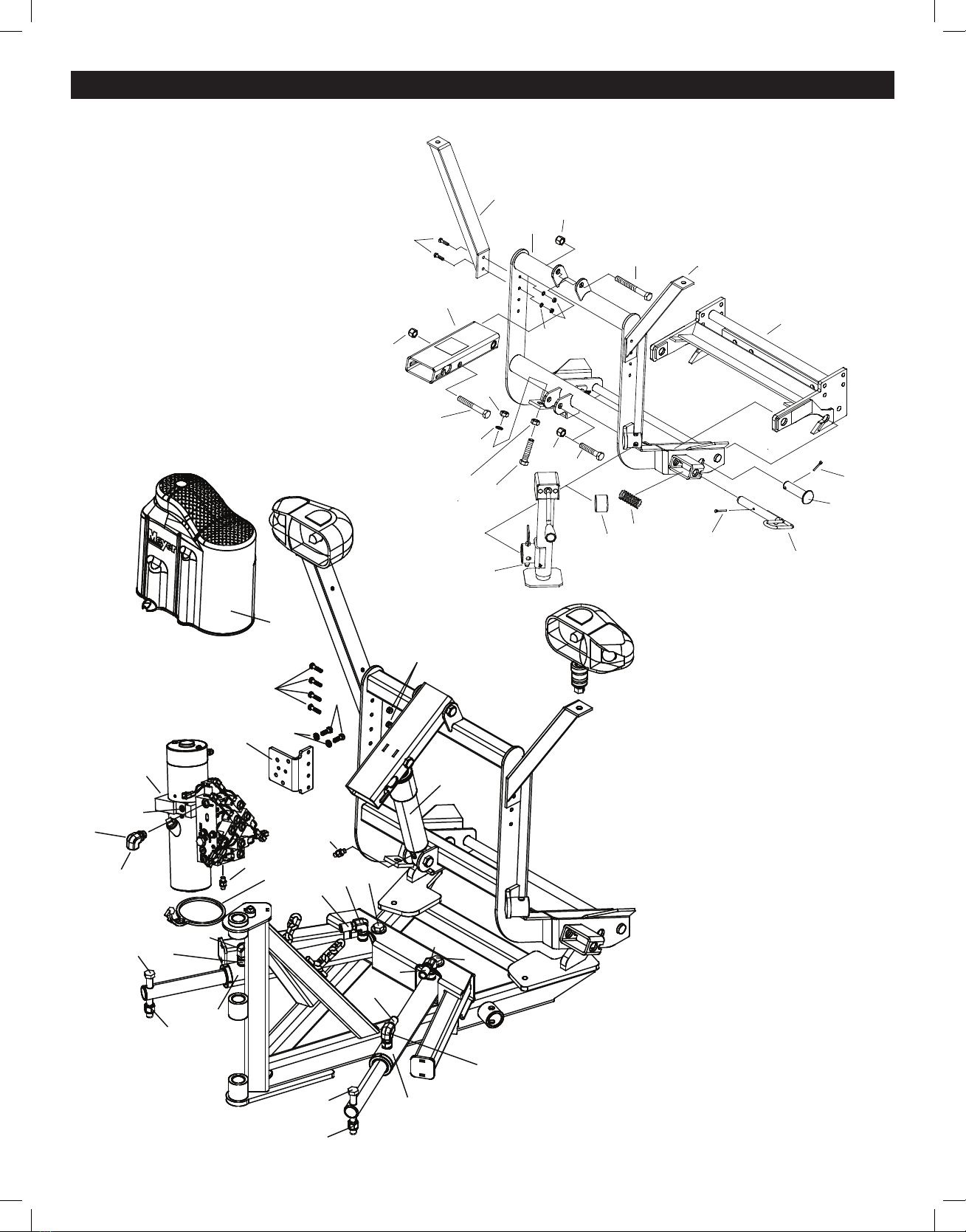
Building Super V Plow
1. Position wing assemblies 75 & 76 face down on cardboard as not to
damage the painted surfaces. Grease the bushings on both left and right
wings. Position the wings so pivot bushings align. Note: Cutting Edges
will be inline at this time.
2. Remove 1/2”-13 x 1” set screw located in top of A-Frame (37) tower. Grease
A-Frame (37) bushings and Pivot Pin (36). With a helper, lift the A-Frame (37) and
insert its bushings in alignment with the wing bushings.
3. Insert Pivot Pin (36) through bushings. Install and tighten 1/2” x 1.50” bolt
(56) and 1/2” lockwasher (59) to top of A-Frame holding Pivot Pin (36) in
place. Note: Wipe o any excess grease at this time.
4. Using the A-Frame as leverage tilt the moldboard assembly raising the
Cutting Edges o the ground. Support Cutting Edges (87) 5 to 6 inches
o the ground.
5. Install the Bottom Belt (71) to left and right wing at Tripedge (77) using
1/2” x 2” carriage bolt (61) and locknut (58). Note: Be sure that Belt (71)
folds are upward and notches are toward the A-Frame (37). Assemble
Backing Plate (54) so bent end is facing the cutting edge forcing the belt
against the Tripedge (77).
6. Using the A-Frame as leverage tilt the moldboard assembly raising the
Cutting Edges o the supports. Remove supports and set moldboard
assembly to the upright position.
7. Assemble Snow Deector Brace (53) to Pivot Pin (36). Place brace under
the pivot pin plate. Attach using two 5/16” x 1-1/4” bolts (55), 5/16
washers (60) and 5/16 locknuts (57).
8. Position moldboard assembly in the “Vee”position.
9. Assemble Top Snow Deector (70) positioning the deector under
deector brace (53). Attach deector ends under left and right wing
gussets using 5/16” x 1-1/4” bolts (55), 5/16 locknuts (57) and 5/16
washers (60). Tighten locknuts such that washers slightly compress the
rubber surface.
Note: Snow Deector Belt should fold/loop downward between brace
and each wing gusset when wings are not in the “Vee” position.
10. Assemble Lift Frame (38) tp A-frame (37) using 1 x 3” Pin (49) and 1/4 x 2”
Cotter Pin (47).
11. Assemble Blue Handle Pin (69) to lift frame (38) by inserting the Blue
Handle Pin (69) through the outer lift frame plates, through the center
of the spring (50). At this time align the small blue leg on the handle
through the notch on the outermost plate. Compress the spring (50)
slightly with your ngers and insert the 3/16” x 1-1/2” Cotter Pin (46)
through the small hole towards the center of the pin. With cotter pin (46)
fully inserted, pull the blue handle until the spring is fully compressed
and rotate the handle one full turn to bend the cotter pin in place.
Realign the small blue leg with the notch on the outermost plate to
lock in place. Repeat assembly process until both pins are assembled.
Note: Lubricate the stainless steel pins and Lift Frame bearing surfaces
with chassis grease or anti-seize lubricant periodically for easier
disengagement of pins.
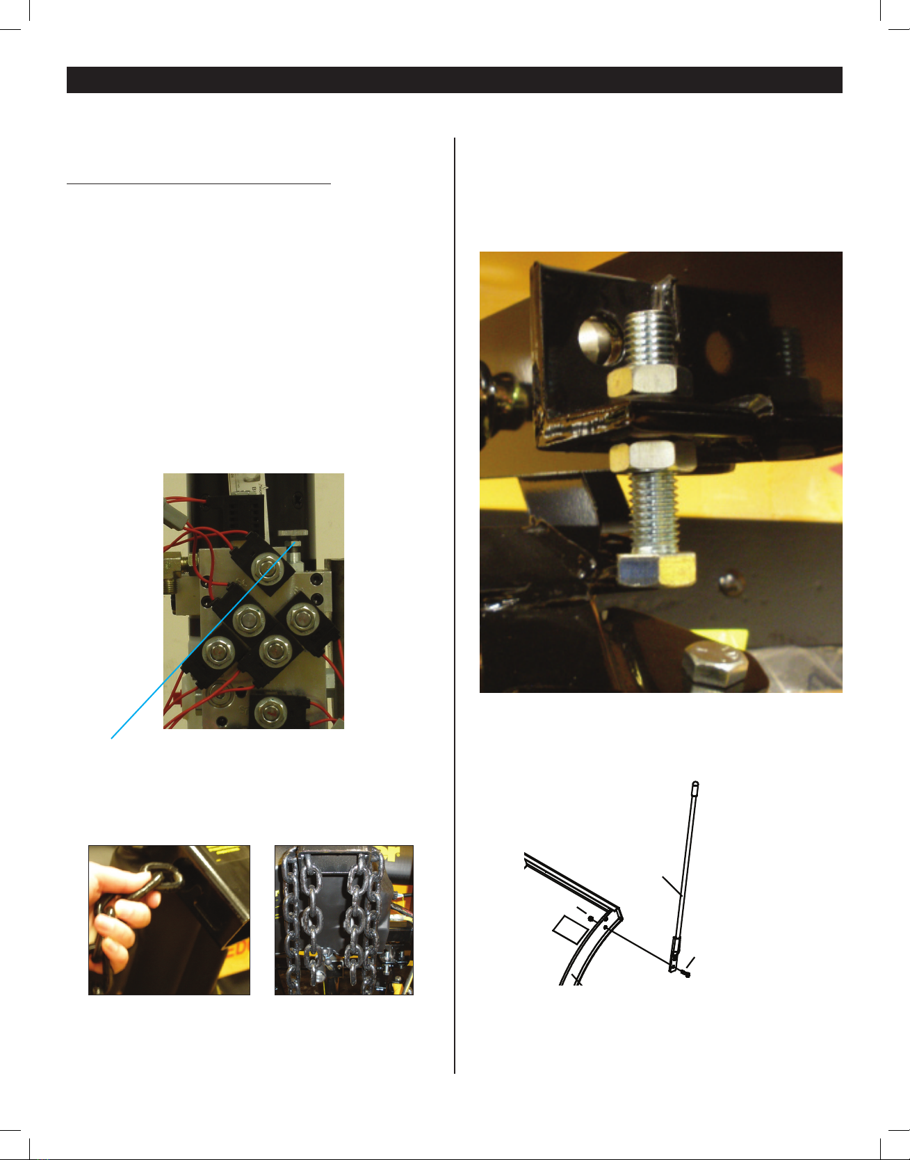
12. Assemble adjustable stacking stop bolts to lift frame (38) using 5/8-11
x 3” bolts (51), lockwasher (52) and jamnuts (52) per gure1. Note:
Adjustment must be made after moldboard assembly is installed.
Adjustment bolts (51) should make contact with the a-frame before
any part of the A-Frame or moldboard come in contact with the lift arm
and, or hydraulic unit while raising the snowplow or stacking snow.
Moldboard should be checked in all positions.
13. Attach L.H. and R.H. Light Brackets (66 & 67) to the side plates of Lift
Frame (38) in the upper two holes using 5/16”-18 x 1-1/4” bolts (39), 5/16”
lockwashers (44), and 5/16”-18 hex nuts (48). Note: Light brackets may
be adjusted down two levels in height for better appearance on lower
prole vehicles. Tighten all fasteners to their proper torque.
14. Attach lift arm (73) to lift frame (38) using 5/8-11 x 5-1/2” bolt (42) and 5/8-11
locknut (43).
15. Install the V-70 Mounting Bracket (28) to the Lift Frame and Light Bracket
(Passenger Side) using 5/16-18 x 1-1/2” Bolts (16) and 5/16-18 Locknuts
(20). Install the V-70 Lift Assembly (29) to V-70 Mounting Bracket Assem-
bly using Bolt H 3/8-16 x 1-1/4” (17) and 3/8 Lockwasher (22). Remove
shipping plug on V-70 Lift Assembly and install Breather (14).
16. Attach the Lift Cylinder (2) to the Lift Frame using Bolt H 5/8-11 x 3-1/4”
( 40) and 5/8-11 Locknut (43). Attach the Lift Cylinder (2) to the Lift Arm
using Bolt H 5/8-11 x 4-3/4” (41) and 5/8-11 Locknut (43). Attach elbow
(26) to V-70 Lift Assembly (29) along with Hose (34) and attach hose (34)
to Lift Cylinder (2) using Straight Fitting (27).
17. Attach xed end of Wing Cylinders (5) to the A-Frame with a 5/8-11 x 5”
bolt (18) and 5/8-11 locknut (21) on each side. Attach live end of Wing
Cylinder rod (5) to the Wings using a 5/8-11 x 5” bolt (19) and 5/8-11
locknut (21) on each side.
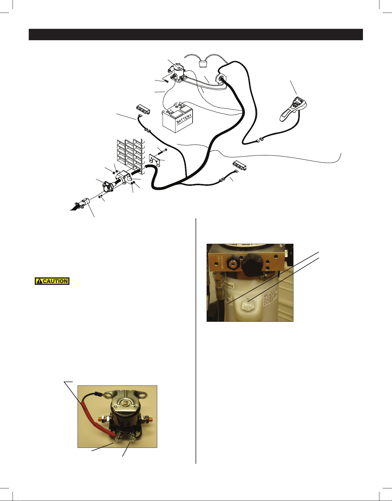
18. Attach Wing Cylinders hoses to the V-70 Lift Assembly (29) by removing
the caps from the hoses (6 & 7) and plugs from the V-70 Lift Assembly
(1). Install Straight Fittings (27) to bottom of PA Block on V-70 Hydraulic
Unit and connect hoses. See below. Use zip ties to route hoses away from
moving plow parts to prevent chang.
19. Connect Super V Plow Side Harness (33) toV-70 Hydraulic Unit (29) as
shown below.
Pass Side
Live End
(1/4 Hose)
Driver Side
Live End
(1/4 Hose)
Pass Side
Fixed End
(3/8 Hose)
Driver Side
Fixed End
(3/8 Hose)
Drain
Fill
S1
S2
S3
S4
S5
S6
S7
S8
Lift
Cylinder
Hose
Port
COIL COLOR CODE
S1 - RED WIRE
S2 & S7 - BLACK WIRE
S3 - GREEN WIRE
S4 - YELLOW WIRE
S8 & S8 - BLUE w/WHITE STRIPE
S6 - PURPLE WIRE

Free Plowing).
23. Meyer M-1 Hydraulic Fluid Part No. 15134 may need to be added to
reservoir and bleed the Angle Cylinders, proceed as follows:
a. Remove Fill Plug from reservoir to add uid during charging.
b. Operate the Angle cylinders (2) until they are lled with Meyer M-1
Hydraulic Fluid and are not spongy.
c. Top o the unit to the ll line on the reservoir with Meyer M-1 Hydraulic Fluid.
NOTE: Proper uid level is to the ll line on the reservoir for the V-71.
(S) terminal white wire
(I) terminal black wire w/white stripe
15059 Diode packed in Controller box
20. Run Universal Truck Side Harness (32) through a hole in grille and into
the engine compartment. Sandwich vehicle grill between Plug Bracket(8)
and Plate (9) using Bolt H 5/16-18 x 3” (13), 5/16 Lockwasher (11) and
5/16-18 Finish nut (12). Secure Universal Truck Side Harness (32) to Plug
Bracket (8) using Bolt H 5/16-18 x 1” (10), 5/16 Lockwasher (11) and 5/16-
18 Finish nut (12).
Secure Universal Truck Side Harness (32) from any hot /
moving parts with tie wraps as needed.
21. Drill a 1-1/4” Diameter Hole thru rewall and extend the harness into the
cab of the vehicle. Fused lead from Universal Truck Side Harness (32) must
be attached to terminal in fuse panel that is activated only when the igni
tion key is “on.”
22. Install Motor Solenoid (30) to metal surface in engine compartment using
SelfTapping Screws (24). (Solenoid must be grounded to operate). Attach
Red Power Cable (32) to a large terminal on Motor Solenoid (30). Attach
Black Ground Cable (32) to negative (-) terminal of battery. Attach Red
Power Cable (1) to positive (+) terminal of battery and remaining large
terminal on Motor Solenoid (30). Attach small white wire from harness
(32) to small terminal (S) on Motor Solenoid (30). Attach small Black/white
stripe wire from harness (32) to small terminal (I)(ground) on Motor Sole
noid (30) Attach Blue wire to a reverse signal on the vehicle. The blue wire
is sensing when the vehicle is in reverse in order to operate HFP (Hands
V-71 Fill level line
V-71 Fill Plug
(6)
Vehicle Side Wiring Diagram
32
1
Optional
Controller
30
24
8
9
10
13
11
12
33
Keyed Ignition (Blue)
Light Module "C" Harness
Light Module "B" Harness (Orange)
Red
Red
Black
Whi te
Blue Wi re
Light Module "C" Harness
Reverse
Signal
Bl ack/White
Stripe
11
12

It must be checked with the lift cylinder and both wing cylinders fully
retracted.
For snow plow light installation see separate instructions.
Orange wire on Harness (32) will attach to both orange wires of the “B”
harness supplied in the Light Module Kit. Reference Form 1-757
Route Cables“C” (Yellow) from module to Harness (32). Connect both “C”
Harness female ends to the male corresponding ends of the Harness (32).
Connect both male ends from the snow plow light to the female ends on
the Plow Side Harness (33).
Check snow plow light blinkers to make sure the wires have not been reversed.
Note: All electrical connections should have both ends coated with a
dielectric grease, Meyer Part No. 15632, prior to nal installation. This will
ensure a good connection and help in preventing corrosion.
24. Refer to Operation and Maintenance Manual for complete controller operation.
25. After all electrical connections have been made the drop speed of the
plow may be evaluated / adjusted. To adjust, loosen the hex nut
and adjust in to slow the drop speed and out to make it faster. After ideal
drop speed it achieved, retighten the hex nut. See below.
V-70 Lower Adjustment:
Loosen jam nut and turn knob clockwise to slow the drop of the plow and counter
clockwise to speed the drop of the plow. Tighten jam nut.
After cycling of the plow, recheck oil level.
(7)
27. Assemble adjustable stacking stop bolts to lift frame (38) using
5/8-11 x 3” bolts (51), lockwasher (45) and jamnuts (52). See below.
Note: Adjustment must be made after moldboard assembly is installed.
Adjustment bolts (51) should make contact with the a-frame before any
part of the A-Frame or moldboard come in contact with the lift arm and,
or hydraulic unit while raising the snowplow or stacking snow. Moldboard
should be checked in all positions.
28. Attach Plow Markers (62) to moldboard using 5/16-18 x 1” Bolt (63), 5/16” Flatwasher
(65) and 5/16-18 Locknut (64).
26. Attach the Lift Chain to the Lift Arm (73) through the two hooks on the
lift arm. Adjust the lift chain at the lift arm so that there are 2-3 links of
slack. This ensures that the plow blade will lift fully and be able to follow
the ground contour while plowing.
75
76
87
88
89
71
54
58
61
80
81
36
70
60
57
55
78
79
82
83
84
85
64
63
62
53
55
56
57
57
59
60
37
60
20
22
77
71
58
61
54
84
85
81
80 87
77
76
75
78,79 & 86
82
83
88 & 89

Meyer Products assumes no responsibility for installations not
made in accordance with these instructions.
A.Pullvehicleintoplowassembly
andpushplowassemblyforwardan
inch or two.
F. Attachcrankstandtoliftframe.
E. Remove crankstand from
a-frame.
D. Adjust crankstand until it is no
longerincontactwiththeground.
C. Push back on lift frame until
both pins spring thru mount
on vehicle.
B.Twist handles on both sides to
engage spring loaded pins.
G.Removeweathercoveronmaleendandconnectonepieceelectricalplug.Thespring
loaded cover will lock one piece plug.
For Mounting and Dis-mounting instructional video’s please visit www.youtube.com/meyerproducts
(8)
Mount Plow To Vehicle

A.Press down button until oat light
turns blue.
B. Push lift arm down until there is slack in the chain.
C. Remove crankstand from lift frame.
D. Attach crankstand to a-frame
E. Adjust crankstand until
crankstand comes into contact
with the ground and then turn
1 to 2 revolutions.
F.Whileslightlypushingtheliftframetowardsvehiclepullhandlesoneithersidetodisengage
pins then twist until the leg locks the pin in the open position.
G.Disconnectonepieceelectrical
plugandinstallweathercoveron
male end.
H. Back vehicle away from plow
assembly.
Meyer Products assumes
no responsibility for
installations not made in
accordance with these
instructions.
(9)
For Mounting and Dis-mounting instructional video’s please visit www.youtube.com/meyerproducts
Dis-Mount Plow From Vehicle

Vehicle Make: Vehicle Model:
Vehicle Year: Vehicle VIN#:
Vehicle FGAWR: Installing Company:
Mounting Type: Plow Type:
EZ Plus 7.5
Hydraulic Serial Number: Moldboard Serial Number:
Comments:
Inspected By: W.O.# Date:
Customer Signature:
PRE-DELIVERY INSPECTION
All bolts torqued to specication
Suspension interference
Clevis height in inches
Diode Installed
Trip springs adjusted
Lift Chain Adjusted
Check for hydraulic uid leaks
Hydraulic uid Level
Dielectric grease applied to ALL electrical connection
All wires/modules secured
Plow Stops Adjusted (plow cannot bump hyd. unit)
Controller Operation
Controller Turns O when vehicle shut o
Plow Operation Up
Plow Operation Left & Right
Plow Operation Vee, Scoop Left & Right Wing In & Out
Plow Operation Down
Plow Drop Speed Adjusted
Plow Light Blinker Left & Right Operation
Plow Light Low & High Beam Operation
Plow Lights Adjusted
Plow Mount/Dismount reviewed with Customer
Plow Operation reviewed with Customer
HFP (Hands Free Plowing) reviewed with Customer
Warranty/Registration/Owners Manual
reviewed with Customer
(10)
11-1/4"
Clevis height
Serial Number Decal Locations
V-71 unit serial number is
under the cover attached to the
hydraulic unit.
Moldboardserialnumberisattachedtothe
back of the moldboard.
Please see your owner’s manual for Pre-Season, Post-Season and general maintenance.

CUTTING EDGE KITS DEFLECTOR KITS
POLY STEEL
Lt Pro Moldboard and A CURB SNOW CENTER CENTER
PART NO. DESCRIPTION Steel Rubber Urethane Molded Rubber Poly GUARDS SHOES EDGE EDGE
51200 SV LD 7.5 STEEL 09112* 08247 09333 N/A 13274 N/A N/A 09214 N/A N/A
(11)
Super V LD Moldboard Accessories
Controllers and Controller Accessories
*Included with moldboard
Mounting Accessories
22869X
Pistol Grip Controller
22799
Joy Stick
Cradle Mount
22798
Pistol Grip
Cradle Mount
22815
45-Degree
Cradle Adapter
22801 (10”)
22844 (20”)
Floor Mount
16529
Meyer
Winch Cradle
08300 Brush Guard
Optional Light Guards
16536 (‘99-07 Ford)
16537 (‘99 + Chevy)
16539 (‘99 + Dodge)
Please visit http://www.meyerproducts.com/plows/lotpro.aspx for a complete listing of accessories
© 2016 Printed in the U.S.A.
Meyer Products LLC
18513 Euclid Ave. • Cleveland, Ohio 44112-1084
Phone 216-486-1313
www.meyerproducts.com• email [email protected]
Table of contents
Other Meyer Snow Blower manuals

Meyer
Meyer Drive Pro LD Guide

Meyer
Meyer V-66 QUIK LIFT User manual

Meyer
Meyer Diamond MD II User manual

Meyer
Meyer Path Pro2 Guide

Meyer
Meyer LotPro 41325 Instruction Manual

Meyer
Meyer EZ-MOUNT XPRESS AG-7.5 User manual

Meyer
Meyer power box 810 User manual

Meyer
Meyer WingMan 28300 Instruction Manual

Meyer
Meyer Super-V3 User manual
Popular Snow Blower manuals by other brands

Craftsman
Craftsman 247.88833 Operator's manual

Toro
Toro 38360 - Power Shovel 7.5 Amp Snow Thrower/Electric... Operator's manual

Land Pride
Land Pride SBL2566 Operator's manual

Fisher Engineering
Fisher Engineering Insta-Act Snowplow installation instructions

Case
Case BS163H Operator's manual

SNOWJOE
SNOWJOE iON iON18SBRM Operator's manual