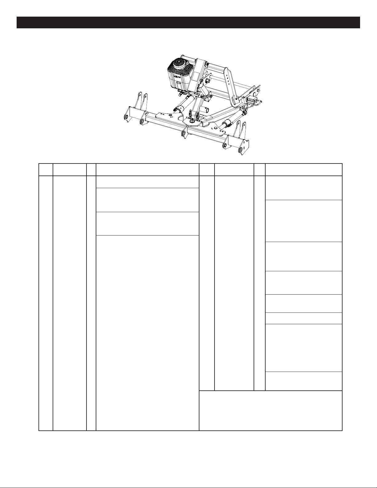
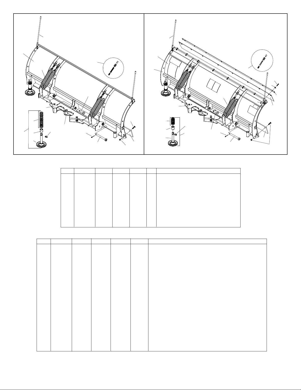
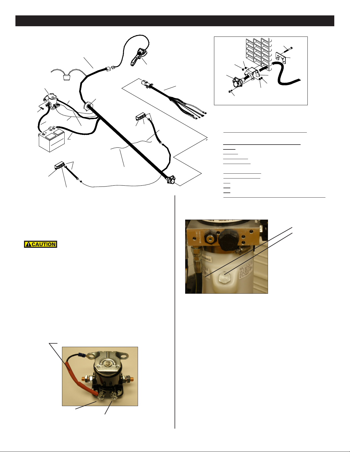
Meyer LotPro 41325 Instruction Manual

Form No. 1-1106R
June 2017
EZ Build Assembly and Installation
41325 Lot Pro Plow with E-72 12V Hydraulic Unit
© 2014 Printed in the U.S.A.
Meyer Products LLC
18513 Euclid Ave. • Cleveland, Ohio 44112-1084
Phone 216-486-1313
Meyer Products LLC reserves the right, under its continuing product
improvement program, to change construction or design details,
specications and prices without notice or without incurring any obligation.

Table of Contents
General Information..................................................................................................................................................................................................1
Illustrated Parts Lists............................................................................................................................................................................................ 2-4
Attaching Plow to EZ Build Assembly.........................................................................................................................................................................5
Vehicle Side Wiring Diagram ................................................................................................................................................................................. 6-7
Drop Speed Adjustment............................................................................................................................................................................................7
Stop Bolt Adjustment................................................................................................................................................................................................7
Mount Plow System To Vehicle..................................................................................................................................................................................8
Dis-Mount Plow System From Vehicle .......................................................................................................................................................................9
Pre-Delivery Inspection...........................................................................................................................................................................................10
Accessories...........................................................................................................................................................................................................11
Web Based Support
(1)
GENERAL INFORMATION
Always disconnect battery prior to installation.
SAFETY PRECAUTIONS should be used when Quik Lift® is in a RAISED position.
LOWER plow to the ground when vehicle is PARKED.
OVERHAUL and SERVICE information is covered on separate instructions.
Lift arm should be removed from vehicle if / when snowplow is removed.
Note:
1. Connect ground cable to negative side of battery for a solid connection to ground.
2. Route all cables away from moving engine parts, Manifolds, and sharp sheet metal.
3. For weather protection, coat all connections with Meyer Dielectric Grease Part No. 15632
4. The vehicle must be equipped with a “Heavy Duty Battery” (70 Amp, Hr. Min.), 550 C.C.A. and “Alternator” (60 Amp. Min.) to obtain maximum performance.
5. Follow these instructions explicitly. Warranty does not apply to a Meyer product which has been negligently or improperly assembled or installed.
ADDITIONAL BATTERY CONNECTIONS
1. When attaching cables to battery with side post terminals, use M.P. Adaptor Part #21976.
2. Coat battery connections with battery terminal coating. Bolt Nut Size Gr. 2 Gr. 5Gr. 8
1/4 - 20 4 - 5
5/16 - 18 9 - 11
3/8 - 16 17 - 20 26 - 29
7/16 - 14 42 - 46 60 - 66
1/2 -13 64 - 72 90 - 100
5/8 - 11 127 - 141 179 - 198
TORQUE CHART FOOT POUNDS
Please check the contents of your crate. Page 2 shows the assembled parts in the left hand column and the accessory box in the right hand column.
Page 3 is the diagram for the left hand column of page 2.
http://www.meyerproducts.com/
TechSupport/ServiceManualsandIn-
stallationInstructions.aspx
http://www.meyerproducts.com/
techsupport/EZtroubleshooter.aspx
http://www.meyerproducts.com/
TechSupport/OwnersManuals.aspx
http://www.youtube.com/playlist?list
=PLDE0602B305314D92&feature=e
dit_ok
Service Manuals EZ-Troubleshooter Owners Manual Mount/Dismount Videos
Please visit our website to nd our most updated technical information.
Tool list for Plow assembly:
Pliers
1/2"socket
1/2"box wrench
9/16"box wrench
9/16"socket
3/4"box wrench
15/16"box wrench
15/16"deep well socket

Parts Diagram
Parts List
Parts indented are included in the carton, bag or assembly under which they are indented.
E-72 PKG
Item Part No. Qty. Description
41325 1 LP 7.5-9.0 E58H Plus Mount Assy.
1 05815 1 Lift Ram 1.75 x 8”
07708 1 • L.H. Ram with Hose & Fittings
2 05877 1 •• Ram (1-1/2” x 10”)
3 22866 1 •• SAE Mx3/8 90 Degree Elbow
4 22885 1 •• Hose 1/4 x 54”
07709 1 • R.H. Ram with Hose & Fittings
2 05877 1 •• Ram (1-1/2” x 10”)
3 22866 1 •• SAE Mx3/8 90 Degree Elbow
4 22884 1 •• Hose 1/4 x 33”
5 11859 2 • Blue Handle Pin
6 12750 1 • Pivot Bar Lot Pro
7 13333 1 • E-72 Mounting Bracket
8 13940 1 • A-Frame Lot Pro Plus
8a 21541 2 • Chain 5/16 x 38” Gr. 43
8b 8518001026 2 • U-Bolt 7/16-14
8c 20306 4 • Locknut 7/16-14
9 15645 1 • Lift Unit Cover
10 15634 1 • Cover Strap
11 16006 1 • Lift Ass’y. (Unit only)
12 19365 1 • Lift Frame
13 19370 1 • Clevis
14 19592 1 • Lift Arm
15 20029 4 • Bolt H 5/16-18 x 1-1/2” Gr. 2
16 20049 2 • Bolt H 3/8-16 x 1” Gr. 2
17 20146 1 • Bolt H 5/8 - 11 x 3-1/4” Gr. 5
18 20147 2 • Bolt H 5/8 - 11 x 3-1/2” Gr. 5
19 20150 2 • Bolt H 5/8 - 11 x 4-1/2” Gr. 5
20 20152 1 • Bolt H 5/8 - 11 x 5” Gr. 5
21 20153 1 • Bolt H 5/8 - 11 x 5-1/2” Gr. 5
22 20304 4 • Locknut 5/16-18
23 20309 7 • Locknut 5/8-11
24 20327 2 • Lockwasher 3/8”
25 20331 2 • Lockwasher 5/8”
26 20406 3 • Cotter Pin 3/16 x 1-1/2”
27 20420 2 • Cotter Pin 1/4 x 2”
28 22245 1 • Crank Stand
29 22274 1 • Slotted Nut 1-8
30 22398 1 • King Bolt 1-8 x 5-1/2”
31 22436 2 • Pin 1 x 3”
32 22692 1 • Plow Side Harness
33 22866 1 • SAE Mx3/8 90 Degree Elbow
34 22883 1 • Hose 1/4 x 22”
E-72 PKG
Item Part No. Qty. Description
41301 1 • Accessory Box
35 05024 1 •• Power Cable - 36”
36 07017 4 •• Trip Spring
07550 1 •• Nite Saber II Kit
08202 1 •• Plug Bracket Kit
37 19607 1 ••• Plug Bracket
38 19609 1 ••• Plate
39 20027 2 ••• Bolt H 5/16-18 x 1 Gr. 2
40 20326 4 ••• Lockwasher 5/16
41 20525 4 ••• Finish Nut 5/16-18
42 22658 2 ••• Bolt H 5/16-18 x 3 Gr. 2
09917 1 •• Plow Marker Kit
43 08214 2 ••• Plow Marker
44 20027 4 ••• Bolt H 5/16-18 x 1 Gr. 2
45 20304 4 ••• Locknut 5/16-18
46 20352 8 ••• Flatwasher 5/16”
47 11751 1 •• Light Bracket LH
48 11752 1 •• Light Bracket RH
49 11844 1 •• Receiver Tube Cap
50 15370 1 •• Starter Solenoid - 12 volt
15787 1 •• Hardware Bag
51 21398 2 ••• S. Tap Screw 1/4 - 14 x 3/4”
52 21832 1 ••• Split Bushing
53 22690X 1 •• Optional Controller See Page 11
54 22691 1 •• Universal Truck Side Harness
41302 1 •• Hardware Bag
55 09124 4 ••• Eye Bolt
56 20028 4 ••• Bolt H 5/16-18 x 1-1/4 Gr. 2
57 20326 4 ••• Lockwasher 5/16”
58 20406 3 ••• Cotter Pin 3/16 x 1-1/2”
59 20525 4 ••• Finish Nut 5/16-18
60 22331 1 ••• Hex Head Pin 1 x 3-5/16”
61 22375 2 ••• Pivot Pin 1 x 8-3/4”
62 814000005 2 • Spring
63 8500003307001 2 • Bolt H 5/8-11 x 3 Full Thread
64 8501003013 4 • 5/8-11 Jam Nut
41325 E-72 EZ Build
(2)
Meyer Products LLC reserves the right, under its continuing product
improvement program, to change construction or design details,
specications and prices without notice or without incurring any obligation.

41325 E-72
Specic Components
(3)
41325 E-72 Assembly

Item LPP - 7.5 LPP - 8.0 LPP - 8.5 LPP - 9.0 Qty Description
09404 09405 09406 09407 1 Moldboard Assembly
73 09797 09133 09134 07259 1 • Cutting Edge
74 08692 08692 08692 --------- 1 • Bolt C 1/2-13 x 2 & Locknut (Kit of 10 each)
74 --------- --------- --------- 08318 1 • Bolt C 5/8-11 x 2-1/4 & Locknut (Kit of 12 each)
75 12810 12811 12812 12813 1 • Moldboard Frame Weldment
76 12809 12814 12815 12818 1 • Plastic Sheet
76 --------- --------- --------- --------- 1 • Stainless Steel Sheet (304)
77 09362 09362 09362 09362 2 • Mushroom Shoe Casting Assy.
78 12394 12394 12394 12394 1 •• Runner Shoe Casting
79 12449 12449 12449 12449 1 •• Runner Spacer
80 20363 20363 20363 20363 11 •• Flatwasher 1-1/4
81 22083 22083 22083 22083 1 •• Linch Pin
82 12073 12009 12014 12118 1 • Deector
83 12487 12497 12498 12031 1 • Re-Inforcement Bar
84 20051 --------- --------- --------- 8 • Bolt H 3/8-16x1-1/2”
84 --------- 20051 20051 20051 10 • Bolt H 3/8-16x1-1/2”
85 20305 --------- --------- --------- 8 • Locknut 3/8-16
85 --------- 20305 20305 20305 10 • Locknut 3/8-16
86 20353 --------- --------- --------- 8 • Flatwasher 3/8”
86 --------- 20353 20353 20353 10 • Flatwasher 3/8”
Lot Pro Poly Parts List
Item LP - 7.5 LP - 8.0 LP - 8.5 LP - 9.0 Qty Description
65 09400 09401 09402 09403 1 Moldboard Assembly
66 09797 09133 09134 07259 1 • Cutting Edge
67 08486 --------- --------- --------- 1 • Bolt C 1/2-13 x 1-3/4 & Locknut (Kit of 9 each)
67 --------- 08692 08692 --------- 1 • Bolt C 1/2-13 x 2 & Locknut (Kit of 10 each)
67 --------- --------- --------- 08318 1 • Bolt C 5/8-11 x 2-1/4 & Locknut (Kit of 12 each)
68 09362 09362 09362 09362 2 • Mushroom Shoe Casting Assy.
69 12394 12394 12394 12394 1 •• Runner Shoe Casting
70 12449 12449 12449 12449 1 •• Runner Spacer
71 20363 20363 20363 20363 11 •• Flatwasher 1-1/4
72 22083 22083 22083 22083 1 •• Linch Pin
Parts indented are included in the assembly under which they are indented.
Lot Pro Steel Parts List
Lot Pro Steel Lot Pro Poly
65
66
67
68
69
70
71
72
6
36
43-46
55
60
61
67
58
58
73
74
75
76
77
78
79
80
81
82
83
84
85
86
6
36
43-46
55
60
61
58
(4)
Meyer Products LLC reserves the right, under its continuing product
improvement program, to change construction or design details,
specications and prices without notice or without incurring any obligation.

A. Attach L.H. and R.H. Light Brackets (47 & 48) to the side plates of Lift Frame
(12) in the upper two holes using 5/16”-18 x 1-1/4” bolts (56), 5/16” lockwashers
(57), and 5/16”-18 hex nuts (59). Note: Light brackets may be adjusted down two
levels in height for better appearance on lower prole vehicles. Tighten all fasteners
to their proper torque.
73
74
75
76
77
78
79
80
81
82
83
84
85
86
6
36
43-46
55
60
61
58
B. Liberally coat Pivot Pins (60 & 61) with Coolube Multi-Purpose Premium
Grease Part No. 15181.
C. Attach Pivot Bar (6) to Moldboard with Pivot Pins (60 & 61) (grease tting facing
outward) and insert Cotter Pins (58). Grease outer Pivot Pin’s (52) using grease tting.
9
7
15
24
34 11
10
16
22
34
1
33
9
10
11
2
3
4
5
6
8
12
13
14
17
18
19
21
2
3
4
20
23
25
26
27
28
29
30
31
23
23
23
23
26
47
48
49
62
63 64
56
57 59
20309
20530
07031
RIB
07017
D. Attach Eye Bolts (55) to Moldboard and Trip Springs (36) to Pivot Bar (6), making
certain locknuts are positioned as shown below.
E. Make certain each Eye Bolt (55) is in a vertical position as shown below so that the
Eye Bolt (55) and Trip Spring (36) hinge properly when moldboard trips.
Note: Proper tension is attained when Trip Spring (36) coils just begin to separate
and then tightening top locknut four additional turns. Tighten bottom Locknut (20530)
to secure Eyebolt in position. Install Eyebolt caps (07031) over exposed threads.
F. Attach Plow Markers (43) to moldboard using 5/16-18 x
1” Bolt (44), 5/16” Flatwasher (46) and 5/16-18 Locknut (45)
(5)
G. Attach the Lift Chain to the Lift Arm (14) through the two hooks on the lift arm. Adjust
the lift chain at the lift arm so that there are 2-3 links of slack. This ensures that the
plow blade will lift fully and be able to follow the ground contour while plowing.
65
66
67
68
69
70
71
72
6
36
43-46
55
60
61
67
58
58
Attaching Plow to EZ Build Assembly

BATTERY
POS NEG
Black Ground
Red
"A"
Light
Adapter
"B" Harness
Power/Ground
Park &Turn
"C" Harness
To Plow Light
"A" "B"
"C"
White
Black Blue (Reverse
Signal)
Orange to "B"
harness of light modules
32
35
37
38
39
40
41
42
50
51
53 54
40
41
54
52
K. Meyer M-1 Hydraulic Fluid Part No. 15134 may need to be added to reservoir and
bleed the Angle Cylinders, proceed as follows:
a. Remove Fill Plug from reservoir to add uid during charging.
b. Operate the Angle cylinders (2) until they are lled with Meyer M-1 Hydraulic Fluid
and are not spongy.
c. Top off the unit to the ll line on the reservoir with Meyer M-1 Hydraulic Fluid.
NOTE: Proper uid level is to the ll line on the reservoir for the E-72.
It must be checked with the lift cylinder fully retracted.
(S) terminal white wire
(I) terminal black wire w/white stripe
15059 Diode packed in Controller box
H. Run Universal Truck Side Harness (54) through a hole in grille and into the engine
compartment. Sandwich vehicle grill between Plug Bracket (37) and Plate (38) using
Bolt H 5/16-18 x 3” (42), 5/16 Lockwasher (40) and 5/16-18 Finish nut (41). Secure
Universal Truck Side Harness (54) to Plug Bracket (37) using Bolt H 5/16-18 x 1” (39),
5/16 Lockwasher (40) and 5/16-18 Finish nut (41).
Secure Universal Truck Side Harness (54) from any hot /
moving parts with tie wraps as needed.
I. Drill a 1-1/4” Diameter Hole thru rewall to install split bushing (52) and extend the
harness into the cab of the vehicle. Fused lead from Universal Truck Side Harness (54)
must be attached to terminal in fuse panel that is activated only when the ignition key
is “on.”
J. Install Motor Solenoid (50) to metal surface in engine compartment using Self Tapping
Screws (51). (Solenoid must be grounded to operate). Attach Red Power Cable (54) to
a large terminal on Motor Solenoid (50). Attach Black Ground Cable (54) to negative
(-) terminal of battery. Attach Red Power Cable (35) to positive (+) terminal of battery
and remaining large terminal on Motor Solenoid (50). Attach small white wire from
harness (54) to small terminal (S) on Motor Solenoid (50). Attach small Black/white
stripe wire from harness (54) to small terminal (I)(ground) on Motor Solenoid (50) At
tach Blue wire to a reverse signal on the vehicle. The blue wire is sensing when the
vehicle is in reverse in order to operate HFP (Hands Free Plowing).
Hydraulic Solenoid Color Code:
OPERATION - SOLENOID COMBINATION
RAISE - Motor Solenoid + “B” Solenoid
LOWER - “A” Solenoid Only
LEFT ANGLE - Motor Solenoid Only
RIGHT ANGLE - Motor Solenoid + “C” Solenoid
COIL COLOR CODE
MOTOR SOLENOID - WHITE WIRE
“A” - BLACK WIRE
“B” - RED WIRE
“C” - GREEN WIRE
GROUND WIRE EACH COIL BLACK W/WHITE STRIPE
E-72 Fill level line
E-72 Fill Plug
(6)
Vehicle Side Wiring Diagram

For snow plow light installation see separate instructions.
Orange wire on Harness (54) will attach to both orange wires of the “B” harness
supplied in the Light Module Kit. Reference Form 1-757
Route Cables “C” (Yellow) from module to Harness (54). Connect both “C” Harness
female ends to the male corresponding ends of the Harness (54).
Connect both male ends from the snow plow light to the female ends on the
Plow Side Harness (32).
Check snow plow light blinkers to make sure the wires have not been reversed.
Note: All electrical connections should have both ends coated with a dielectric grease,
Meyer Part No. 15632, prior to nal installation. This will ensure a good connection
and help in preventing corrosion.
L. Refer to Operation and Maintenance Manual for complete controller operation.
M. After all electrical connections have been made the drop speed of the plow may be
evaluated / adjusted. To adjust, loosen the hex nut and adjust in to slow the drop
speed and out to make it faster. After ideal drop speed it achieved, retighten the hex
nut. See below.
After cycling of the plow, recheck oil level.
E-72 Lower Adjustment (left side of hydraulic unit):
Loosen jam nut and turn knob clockwise to slow the drop of the plow and counter
clockwise to speed the drop of the plow. Tighten jam nut.
(7)
N. Assemble adjustable stacking stop bolts to lift frame (12) using
5/8-11 x 3” bolts (63), lockwasher (25) and jamnuts (64). See below.
Note: Adjustment must be made after moldboard assembly is installed. Adjustment
bolts (63) should make contact with the a-frame before any part of the A-Frame/
Sector or moldboard come in contact with the lift arm and, or hydraulic unit while
raising the snowplow or stacking snow. Moldboard should be checked in all positions.

Meyer Products assumes no responsibility for installations not
made in accordance with these instructions.
A. Pull vehicle into plow assembly
and push plow assembly forward an
inch or two.
F. Attach crankstand to lift frame.
E. Remove crankstand from
a-frame.
D. Adjust crankstand until it is no
longer in contact with the ground.
C. Push back on lift frame until
both pins spring thru mount
on vehicle.
B. Twist handles on both sides to
engage spring loaded pins.
G. Remove weather cover on male end and connect one piece electrical plug. The spring
loaded cover will lock one piece plug.
For Mounting and Dis-mounting instructional video’s please visit www.youtube.com/meyerproducts
(8)
Mount Plow To Vehicle

A. Press down button until oat light
turns blue.
B. Push lift arm down until there is slack in the chain.
C. Remove crankstand from lift frame.
D. Attach crankstand to a-frame
E. Adjust crankstand until
crankstand comes into contact
with the ground and then turn
1 to 2 revolutions.
F. While slightly pushing the lift frame towards vehicle pull handles on either side to disengage
pins then twist until the leg locks the pin in the open position.
G. Disconnect one piece electrical
plug and install weather cover on
male end.
H. Back vehicle away from plow
assembly.
Meyer Products assumes
no responsibility for
installations not made in
accordance with these
instructions.
(9)
For Mounting and Dis-mounting instructional video’s please visit www.youtube.com/meyerproducts
Dis-Mount Plow From Vehicle

Vehicle Make: Vehicle Model:
Vehicle Year: Vehicle VIN#:
Vehicle FGAWR: Installing Company:
Mounting Type: Plow Type:
EZ Plus 7.5 8.0 8.5 9.0
Hydraulic Serial Number: Moldboard Serial Number:
Comments:
Inspected By: W.O.# Date:
Customer Signature:
PRE-DELIVERY INSPECTION
All bolts torqued to specication
Suspension interference
Clevis height in inches
Diode Installed
Trip springs adjusted
Lift Chain Adjusted
Check for hydraulic uid leaks
Hydraulic uid Level
Dielectric grease applied to ALL electrical connection
All wires/modules secured
Plow Stops Adjusted (plow cannot bump hyd. unit)
Controller Operation
Controller Turns Off when vehicle shut off
Plow Operation Up
Plow Operation Left
Plow Operation Right
Plow Operation Down
Plow Drop Speed Adjusted
Plow Light Blinker Left & Right Operation
Plow Light Low & High Beam Operation
Plow Lights Adjusted
Plow Mount/Dismount reviewed with Customer
Plow Operation reviewed with Customer
HFP (Hands Free Plowing) reviewed with Customer
Warranty/Registration/Owners Manual
reviewed with Customer
(10)
11-1/4"
Clevis height
Serial Number Decal Locations
E-72 unit serial number is
under the cover attached to the
hydraulic unit.
Moldboard serial number is attached to the
back of the moldboard.
Please see your owner’s manual for Pre-Season, Post-Season and general maintenance.

(11)
Lot Pro Moldboard Accessories
Controllers and Controller Accessories
*Included with moldboard
Mounting Accessories
22790X
Joy Stick
22690DC
Pistol Grip
(Standard)
22695DC
Pistol Grip DLX
22154
Touch Pad
(Need 07691 Adapter)
22799
Joy Stick
Cradle Mount
22798
Pistol Grip
Cradle Mount
22815
45-Degree
Cradle Adapter
22801 (10”)
22844 (20”)
Floor Mount
16529
Meyer
Winch Cradle
08300 Brush Guard
Optional Light Guards
16536 (‘99-07 Ford)
16537 (‘99 + Chevy)
16539 (‘99 + Dodge)
Please visit http://www.meyerproducts.com/plows/lotpro.aspx for a complete listing of accessories
© 2014 Printed in the U.S.A.
Meyer Products LLC
18513 Euclid Ave. • Cleveland, Ohio 44112-1084
Phone 216-486-1313
CUTTING EDGE KITS DEFLECTOR KITS
TRIP-DAMPENING
Lt Pro Moldboard and A CURB ADJ. BOX FIXED COMPLETE
PART NO. DESCRIPTION Steel Rubber Urethane Molded Rubber Poly GUARDS WINGS WINGS WINGS KIT
09400 LP 7.5 STEEL 08178* 08189 08119 12039 08109 12078 08344 08380 08104 08110 08243
09401 LP 8.0 STEEL 08180* 08190 08160 12040 08111 12024 08344 08380 08104 08110 08243
09402 LP 8.5 STEEL 08182* 08191 081621 2041 08112 12025 08344 08380 08104 08110 08243
09403 LP 9.0 STEEL 08185* 08192 08164 12042 08113 12123 08344 08380 08104 08110 08243
09404 LPP 7.5 POLY 08178* 08189 08119 12039 08109 12078* 08344 08380 08104 08110 08243
09405 LPP 8.0 POLY 08180* 08190 08160 12040 08111 12024* 08344 08380 08104 08110 08243
09410 LPS 8.0 STEEL 08180* 08190 08160 12040 08111 12024* 08344 08380 08104 08110 08243
09406 LPP 8.5 POLY 08182* 08191 08162 12041 08112 12025* 08344 08380 08104 08110 08243
09407 LPP 9.0 POLY 08185* 08192 08164 12042 08113 12123* 08344 08380 08104 08110 08243
09411 LPS 9.0 STEEL 08185* 08192 08164 12042 08113 12123* 08344 08380 08104 08110 08243
Table of contents
Other Meyer Snow Blower manuals

Meyer
Meyer Drive Pro LD Guide

Meyer
Meyer WingMan 28300 Instruction Manual

Meyer
Meyer Diamond MD II User manual

Meyer
Meyer power box 810 User manual

Meyer
Meyer 51200 Super V LD Instruction Manual

Meyer
Meyer EZ-MOUNT XPRESS AG-7.5 User manual

Meyer
Meyer Path Pro2 Guide

Meyer
Meyer V-66 QUIK LIFT User manual

Meyer
Meyer Super-V3 User manual