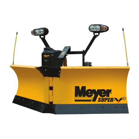
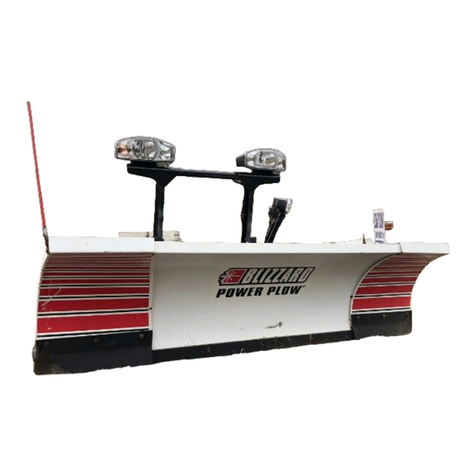
Meyer Super-V3 User manual

Form No. 1-1219R
July 2021
Assembly Instructions
Standard Operating System
V73 12V Hydraulic Unit
Includes
Light Duty: 73200
Steel: 73600, 73700, 73500
Stainless: 73675, 73775, 73575
© 2020 Printed in the U.S.A.
18513 Euclid Ave. • Cleveland, Ohio 44112-1084
Phone 216-486-1313 www.meyerproducts.com

Table of Contents
General Information.........................................................................................................................................................................................................................1
Black Iron Parts Lists.....................................................................................................................................................................................................................2-5
Moldboard Parts List ....................................................................................................................................................................................................................6-7
Plow Assembly & Adjustments...............................................................................................................................................................................................8-10
Standard Operating System Wiring......................................................................................................................................................................................... 11
V73 Hydraulics................................................................................................................................................................................................................................. 12
Mounting Plow................................................................................................................................................................................................................................ 13
Dismounting Plow ......................................................................................................................................................................................................................... 14
Pre-Delivery Inspection................................................................................................................................................................................................................ 15
Registration ...................................................................................................................................................................................................................................... 15
(1)
GENERAL INFORMATION
Always disconnect battery prior to installation.
SAFETY PRECAUTIONS should be used when Quik Lift® is in a RAISED position.
LOWER plow to the ground when vehicle is PARKED.
OVERHAUL and SERVICE information is covered on separate instructions.
Lift arm should be removed from vehicle if / when snowplow is removed.
Note:
1. Connect ground cable to negative side of battery for a solid connection to ground.
2. Route all cables away from moving engine parts, Manifolds, and sharp sheet metal.
3. For weather protection, coat all connections with Meyer Dielectric Grease Part No. 15632
4. The vehicle must be equipped with a “Heavy Duty Battery” (70 Amp, Hr. Min.), 550 C.C.A. and “Alternator”(60 Amp. Min.)............ to
obtain maximum performance.
5. Follow these instructions explicitly. Warranty does not apply to a Meyer product which has been negligently or improperly
assembled or installed.
TORQUE CHART FOOT
Please visit our website to nd our most updated technical information; including installation instructions, user manuals, parts
diagrams, EZ Troubleshooter, and more.
Please see your owner’s manual for Pre-Season, Post-Season, and General Maintenance.
www.meyerproducts.com
Pliers
1/2" socket
1/2" box wrench
9/16" box wrench
9/16" socket
3/4" box wrench
15/16" box wrench
15/16" deep well socket
1/4-20 4-5
5/16-18 9-11
3/8-16 17-20 26-29
7/16-14 42-46 60-66
1/2-13 64-72 99-100
5/8-11 127-141 179-198
Tool List for Plow Assembly
NOTICE:NOTICE: Meyer Products LLC reserves thje right, under its continuing product imporvement program, to change construction, design, details,
specications, and prices without notice or without incurring any obligation. Meyer Products LLC assumes no responsibility for installations not
made in accordance with these instructions.

(2)
Black Iron Parts List

Black Iron Parts List
Parts indented are included in the carton, bag, or assembly under which they are indented.
Item Part # QTY Description
1 05818 1 Lift Ram 1.75 x 8”
2 07910 1 RH Ram Assy 1-1/4 x 12 DA SV3LD
3 05756 1 • Ram 1-1/4” x 12” DA
4 22866 2 • SAE Mx3/8 90° Elbow
5 22941 1 • Hose 3/8” x 33”
6 22884 1 • Hose ¼” x 33”
7 07909 1 LH Ram Assy 1-1/4 x 12 DA SV3ld
8 05756 1 • Ram 1-1/4” x 12” DA
9 22866 2 • SAE Mx3/8 90° Elbow
10 22941 1 • Hose 3/8” x 33”
11 22921 1 • Hose ¼” x 38”
12 22883 1 Hose ¼” x 22”
13 14596 1 Horiz. Hyd Front Cover E73/V73
14 16025 1 Hyd V73 Horiz. 12V
15 14228 1 Horiz. Hyd Rear Cover
16 14290 2 Horiz. Hyd Cover Bracket
17 14589 1 Lift Arm – SV3 7.5LD
18 18955 1 EZ Plus V73 Lift Frame
19 16639 1 Accessory Box – SV3
20 09917 1 • Plow Marker Kit
21 -------- 2 • • Plow Marker
22 20027 4 • • Bolt H 5/16-18 x 1” Gr5
23 20304 4 • • Locknut 5/16-18
24 20352 4 • • Flatwasher 5/16”
25 22022 1 • Crankstand
26 23025 1 • Std Op Sys Power Harness
27 23037 1 • DLX Controller SOS
28 23057 1 • 7 Pin Rnd 4 Pin Flat T-Con
29 23059 1 • SOS HFP Vehicle Harness
30 23067 1 • NS LED 12V Plow Light Kit
31 13207 1 Pivot Pin Super V3
32 11859 2 Blue Handle Pin
33 09512 1 Inner Cut Edge SV3 RH Poly
34 09513 1 Inner Cut Edge SV3 LH Poly
Item Part # QTY Description
35 14557 1 A-frame SV3 7.5LD
36 20800 2 • Quick Link 5/16”
37 21543 2 • Chain 5/16 x 29”
38 14206 2 Inner Cut Edge Strap
39 22866 1 SAE Mx3/8 90° Elbow
40 19370 1 Clevis EZ Mount Plus
41 12548 1 Top Deector SV3 LD 7.5
42 13724 1 Deector Brace
43 14613 2 Top Deector Strap SV3 LD
44 22436 2 Pin 1 x 3”
45 22989 1 Pivot Pin 5/8 x 5-3/4”
46 23050 1 Pivot Pin 5/8 x 4-7/8”
47 21960 4 Bolt C 5/8-11 x 2-1/2”
48 20150 4 Bolt H 5/8-11 x 4-1/2 Gr5
49 20146 1 Bolt H 5/8-11 x 3-1/4 Gr5
50 20102 2 Bolt H ½-13 x 3-1/4 Gr5
51 20095 1 Bolt H ½-13 x 1-1/2 Gr5
52 20309 9 5/8-11 Locknut
53 21262 2 SAE Flatwasher 1”
54 20357 2 Flatwasher 5/8”
55 20049 4 Bolt H 3/8-16 x 1 gr2
56 20307 2 ½-13 Locknut
57 20028 7 Bolt H 5/16-18 x 1-1/4 Gr2
58 20420 2 Cotter Pin ¼ x 2”
59 20355 2 Flatwasher 1/2
60 20027 12 Bolt H 5/16-18 x 1 Gr2
61 814000005 2 Pushbeam Spring
62 20305 4 3/8-16 Locknut
63 20406 2 Cotter Pin 3/16 x 1-1/2”
64 22845 2 Hairpin Cotter 1/8
65 20329 1 Lockwasher ½”
66 20304 15 5/16-18 Locknut
67 20352 15 Flatwasher 5/16”
68 15187 1 Breather, Plastic 3/4” NPT
Super-V3 Light Duty: 73200
(3)

(4)
Black Iron Parts List

Black Iron Parts List
Parts indented are included in the carton, bag, or assembly under which they are indented.
Item Part # QTY Description
1 05818 1 Lift Ram 1.75 x 8”
2 07922 1 RH Ram Assembly 1-1/2 x 12 DA
3 05755 1 • Ram 1-1/2” x 12” DA
4 22866 2 • SAE Mx3/8 90° Elbow
5 22941 1 • Hose 3/8” x 33”
6 22884 1 • Hose ¼” x 33”
7 07923 1 LH Ram Assembly 1-1/2 x 12 DA
8 05755 1 • Ram 1-1/2” x 12” DA
9 22866 2 • SAE Mx3/8 90° Elbow
10 22941 1 • Hose 3/8” x 33”
11 22921 1 • Hose ¼” x 38”
12 22883 1 Hose ¼” x 22”
13 14596 1 Horiz. Hyd Front Cover E73/V73
14 16025 1 Hyd V73 Horiz. 12V
15 14228 1 Horiz. Hyd Rear Cover
16 14290 2 Horiz. Hyd Cover Bracket
17 14439 1 Lift Arm – SV3
18 18955 1 EZ Plus V73 Lift Frame
19 16639 1 Accessory Box – SV3
20 09917 1 • Plow Marker Kit
21 -------- 2 • • Plow Marker
22 20027 4 • • Bolt H 5/16-18 x 1”Gr5
23 20304 4 • • Locknut 5/16-18
24 20352 4 • • Flatwasher 5/16”
25 22022 1 • Crankstand
26 23025 1 • Std Op Sys Power Harness
27 23037 1 • DLX Controller SOS
28 23057 1 • 7 Pin Rnd 4 Pin Flat T-Con
29 23059 1 • SOS HFP Vehicle Harness
30 23067 1 • NS LED 12V Plow Light Kit
31 13207 1 Pivot Pin Super V3
32 11859 2 Blue Handle Pin
33 09512 1 Inner Cut Edge SV3 RH Poly
34 09513 1 Inner Cut Edge SV3 LH Poly
35 14206 2 Inner Cut Edge Strap
36 22866 1 SAE Mx3/8 90° Elbow
Item Part # QTY Description
37 14472 1 A-frame SV3 (8.5/9.5)
38 14459 1 A-frame SV3 (10.5)
39 14521 1 • Lift Frame Stand
40 20095 2 • Bolt H ½-13 x 1-1/2 Gr5
41 20307 2 • ½-13 Locknut
42 20800 2 • Quick Link 5/16”
43 21543 2 • Chain 5/16 x 29”
44 19370 1 Clevis EZ Mount Plus
45 12536 1 Top Deector Super V
46 13724 1 Deector Brace
47 22436 2 Pin 1 x 3”
48 22989 1 Pivot Pin 5/8 x 5-3/4”
49 23050 1 Pivot Pin 5/8 x 4-7/8”
50 21960 4 Bolt C 5/8-11 x 2-1/2”
51 20153 2 Bolt H 5/8-11 x 5-1/2 Gr5
52 20146 1 Bolt H 5/8-11 x 3-1/4 Gr5
53 20152 2 Bolt H 5/8-11 x 5 Gr5
54 20102 2 Bolt H ½-13 x 3-1/4 Gr5
55 20095 1 Bolt H ½-13 x 1-1/2 Gr5
56 20309 9 5/8-11 Locknut
57 21262 2 SAE Flatwasher 1”
58 20357 2 Flatwasher 5/8”
59 20049 4 Bolt H 3/8-16 x 1 gr2
60 20307 2 ½-13 Locknut
61 20028 7 Bolt H 5/16-18 x 1-1/4 Gr2
62 20420 2 Cotter Pin ¼ x 2”
63 20355 2 Flatwasher 1/2
64 20027 4 Bolt H 5/16-18 x 1 Gr2
65 814000005 2 Pushbeam Spring
66 20305 4 3/8-16 Locknut
67 20406 2 Cotter Pin 3/16 x 1-1/2”
68 22845 2 Hairpin Cotter 1/8
69 20329 1 Lockwasher ½”
70 20304 7 5/16-18 Locknut
71 20352 11 Flatwasher 5/16”
73 20150 2 Bolt H 5/8-11 X 4 1/2 Gr5 Zn
(5)
Super-V3: 73600, 73700, 73500
Super-V3 Stainless: 73675, 73775, 73575

Parts indented are included in the assembly under which they are indented.
(6)
Item SV3LD SV3 8’ 6” SV3 9’ 6” SV3 10’ 6” QTY Description
73200 73600 73700 73500 1 Moldboard Assembly
74 09536R 09521R 09522R 09523R 1 R.H. & L.H. Wing
75 09530R 09518R 09520R 09508R 1 • R.H. Wing
76 09531R 09517R 09519R 09509R 1 • L.H. Wing
77 14530 14170 14180 14151 2 • • Trip Edge Weld
78 22438 22438 22438 22438 8 • • 1” x 2-1/2” Pin
79 -------- -------- -------- 22436 2 • • 1” x 3-3/8” Pin
80 21262 21262 21262 21262 8 • • Flatwasher 1”
81 22945 22945 22945 22945 8 • • Roll Pin 5/16” x 1.5”
82 84285 84285 84285 84285 2 • • T-Bar Weldment
83 07215 07215 07215 07215 4 • • Trip Spring
84 20145 20145 20145 20145 2 • • Bolt H 5/8-11 x 3” Gr. 5
85 20318 20318 20318 20318 2 • • Locknut 5/8-11
86 20357 20357 20357 20357 4 • • Flatwasher 5/8”
87 09124 09124 09124 09124 4 • • Eyebolt w/Locknuts and Cap
13274R 12579R 12643R 13045R 1 Deector
Moldboard Parts List

Parts indented are included in the assembly under which they are indented.
(7)
Item Stainless 8’ 6” Stainless 9’ 6” Stainless 10’ 6” QTY Description
73675 73775 73575 Moldboard Assembly
88 09533R 09534R 09535R 1 R.H. & L.H. Wing pkg
89 09524R 09526R 09528R 1 • SS R.H. Wing
90 09525R 09527R 09529R 1 • SS L.H. Wing
91 14494 14496 14498 1 • • RH Moldboard Weld
92 14493 14495 14497 1 • • LH Moldboard Weld
93 14059 14063 14131 1 • • RH Stainless Steel Sheet
94 14060 14064 14132 1 • • LH Stainless Steel Sheet
95 14098 14118 14150 2 • • Bottom Mount Plate
96 14170 14180 14151 2 • • Trip Edge Weld
97 20307 20307 20307 10 • • Locknut ½-13
98 22438 22438 22438 8 • • 1” x 2-1/2” Pin
99 -------- -------- 22436 2 • • 1” x 3-3/8” Pin
100 21262 21262 21262 8 • • Flatwasher 1”
101 21943 21943 21943 10 • • Bolt C ½-13 x 1-3/4”
102 22945 22945 22945 8 • • Roll Pin 5/16” x 1.5”
103 84285 84285 84285 2 • • T-Bar Weldment
104 07215 07215 07215 4 • • Trip Spring
105 20145 20145 20145 2 • • Bolt H 5/8-11 x 3” Gr. 5
106 20318 20318 20318 2 • • Locknut 5/8-11
107 20357 20357 20357 4 • • Flatwasher 5/8”
108 09124 09124 09124 4 • • Eyebolt w/Locknuts and Cap
12579R 12643R 13045R 1 Deector
Moldboard Parts List

(8)
Build Assembly
The SV3 plow comes fully assembled. The instructions below are provided
for additional troubleshooting or component replacement.
1. Position wing assemblies face down on cardboard as not to damage
the painted surfaces. Grease the bushings on both left and right wings.
Position the wings so pivot bushings align. Note: Cutting Edges will be
inline at this time.
2. Remove 1/2”-13 x 1”set screw located in top of A-Frame tower.
Grease A-Frame bushings and Pivot Pin. With a helper, lift the A-Frame
and insert its bushings in alignment with the wing bushings.
3. Insert Pivot Pin through bushings. Install and tighten 1/2”x 1.50” bolt
and 1/2” lockwasher to top of A-Frame holding Pivot Pin in place.
Note: Wipe o any excess grease at this time.
4. Using the A-Frame as leverage tilt the moldboard assembly raising the
Cutting Edges o the ground. Support Cutting Edges 5 to 6 inches o
the ground.
5. Install the Bottom Belt to left and right wing at Tripedge using 1/2”
x 2.75” carriage bolt and locknut. Note: Be sure that Belt folds are
upward and notches are toward the A-Frame. Assemble Backing
Plate so bent end is facing the cutting edge forcing the belt against the
Tripedge.
6. Using the A-Frame as leverage, tilt the moldboard assembly, raising
the Cutting Edges o the supports. Remove supports and set
moldboard assembly to the upright position.
7. Assemble Snow Deector Brace to Pivot Pin. Place brace under the
pivot pin plate. Attach using two 5/16”x 1-1/4” bolts, 5/16 washers
and 5/16 locknuts.
8. Position moldboard assembly in the “Vee”position.
9. Assemble Top Snow Deector positioning the deector under deector
brace. Attach deector ends under left and right wing gussets
using 5/16” x 1-1/4” bolts, 5/16 locknuts and 5/16 washers. Tighten
locknuts such that washers slightly compress the rubber surface.
Note: Snow Deector Belt should fold/loop downward between brace
and each wing gusset when wings are not in the “Vee” position.
10. Assemble Lift Frame to A-frame using 1 x 3” Pin and 1/4 x 2” Cotter
Pin.
11. Assemble Blue Handle Pin to lift frame by inserting the Blue Handle
Pin through the outer lift frame plates, through the center of the spring.
At this time align the small blue leg on the handle through the notch
on the outermost plate. Compress the spring slightly with your ngers
and insert the 3/16” x 1-1/2” Cotter Pin through the small hole towards
the center of the pin. With cotter pin fully inserted, pull the blue handle
until the spring is fully compressed and rotate the handle one full
turn to bend the cotter pin in place. Realign the small blue leg with
the notch on the outermost plate to lock in place. Repeat assembly
process until both pins are assembled. Note: Lubricate the stainless
steel pins and Lift Frame bearing surfaces with chassis grease or anti-
seize lubricant periodically for easier disengagement of pins.
12. Assemble adjustable stacking stop bolts to lift frame using 5/8-11 x
3” bolts, lockwasher and jamnuts. Note: Adjustment must be made
after moldboard assembly is installed. Adjustment bolts should make
contact with the a-frame before any part of the A-Frame or moldboard
come in contact with the lift arm and, or hydraulic unit while raising
the snowplow or stacking snow. Moldboard should be checked in all
positions.
13. Attach L.H. and R.H. Light Brackets to the side plates of Lift Frame in
the upper two holes using 5/16”-18 x 1-1/4” bolts, 5/16” lockwashers,
and 5/16”-18 hex nuts. Note: Light brackets may be adjusted down
two levels in height for better appearance on lower prole vehicles.
Tighten all fasteners to their proper torque.
14. Attach lift arm to lift frame using 5/8-11 x 5-1/2” bolt and 5/8-11
locknut.
15. Install the U-73 Mounting Bracket to the Lift Frame and Light Bracket
(Passenger Side) using 5/16-18 x 1-1/2”Bolts and 5/16-18 Locknuts.
Install the U-73 Lift Assembly to U-73 Mounting Bracket Assembly
using Bolt H 3/8-16 x 1-1/4” and 3/8 Lockwasher. Remove shipping
plug on U-73 Lift Assembly and install Breather.
16. Attach the Lift Cylinder to the Lift Frame using Bolt H 5/8-11 x 3-1/4”
and
5/8-11 Locknut. Attach the Lift Cylinder to the Lift Arm using Bolt
H 5/8-11 x 4-3/4” and 5/8-11 Locknut. Attach elbow to U-73 Lift
Assembly along with Hose and attach hose to Lift Cylinder using
Straight Fitting.
17. Attach xed end of Wing Cylinders to the A-Frame with a 5/8-11 x 5”
bolt and 5/8-11 locknut on each side. Attach live end of Wing Cylinder
rod to the Wings using a 5/8-11 x 5” bolt and 5/8-11 locknut on each
side.
18. Attach Wing Cylinders hoses to the U-73 Lift Assembly by remov-
ing the caps from the hoses and plugs from the U-73 Lift Assembly.
Install Straight Fittings to bottom of PA Block on U-73 Hydraulic Unit
and connect hoses. See below. Use zip ties to route hoses away from
moving plow parts to prevent chang.
19. Connect Super V Plow Side Harness to U-73 Hydraulic Unit as shown
on the following page.

(9)
Plow Assembly & Adjustments
Plow MarkersPlow Markers
Attach Plow Markers (21) to moldboard using 5/16-18 x 1”Bolt (22), 5/16”
Flatwasher (24) and 5/16-18 Locknut (23).
Nite Saber LED LightsNite Saber LED Lights
See seperate Nite Saber LED instructions for further information.
Mount the lights as shown below.
Connect both male ends from the snow plow light to the female ends on
the Plow Side Harness. Ensure all wiring harnesses are secured against the
lift frame.
Check snow plow lights and blinkers to ensure proper operation. If operat-
ing in reverse (i.e. driver side blinking instead of passenger side), reverse the
harness connections.
Note: All electrical connections should have both ends coated with a dielec-
tric grease (Meyer Part # 15632) prior to nal installation. This will ensure a
good connection and help in preventing corrosion.
Nite Saber LED Parts List
Item Part QTY Description
1 23067 1 Nite Saber LED Kit
- 23066 1 • Passenger Side LED
- 23065 1 • Driver Side LED
2 08126 1 • Hardware Bag
3 ----- 8 • • Hex Bolt 3/8” x 3/4”, SS
4 ----- 8 • • Hex Nut 3/8”, SS
5 ----- 8 • • Lock Washer 3/8”, SS
6 ----- 2 • • Metal Bracket, Bottom
7 ----- 2 • • Bolt 1/2”- 13 x 1 1/12”, SS
8 ----- 2 • • Hex Lock Nut 1/2”- 13, SS
9 ----- 4 • • Flat Washer 1/2”, SS
10 ----- 2 •• Neoprene Grommet 1/2”
Trip Spring AdjustmentTrip Spring Adjustment
Attach Eye Bolts to Moldboard and Trip Springs to Pivot Bar, making
certain locknuts are positioned as shown below.
Make certain each Eye Bolt is in a vertical position as shown below so that
the Eye Bolt and Trip Spring hinge properly when the Moldboard trips.
Note: Proper tension is attained when the Trip Spring coils just begin to
seperate and then tightening top locknut four additional turns. Tighten
bottom locknut to secure Eye Boilt in positiion.
Install Eye Bolt Caps over exposed threads.
Parts indented are included in the carton, bag, or assembly
under which they are indented.

(10)
Plow Assembly & Adjustments
Lift ChainsLift Chains
Attach the Lift Chain to the Lift Arm through the two hooks on the lift
arm. Adjust the lift chain at the lift arm so that there are 2-3 links of slack.
This ensures that the plow blade will lift fully and be able to follow the
ground contour while plowing.
Drop Speed AdjustmentDrop Speed Adjustment
Drop Speed Adjustment: Loosen jam nut and turn knob clockwise to slow
the drop of the plow and counter clockwise to speed the drop of the plow.
Tighten jam nut.
Drop Speed Adjustment
Hydraulic Fluid LevelHydraulic Fluid Level
Top o the unit to the ll line on the reservoir with Meyer M-1 Hydraulic
Fluid.
NOTE: Proper uid level is to the ll line on the reservoir. It must be checked
with the lift cylinder fully retracted.

(11)
Wiring Harnesses & Controller
Vehicle Side HarnessVehicle Side Harness
1) Route the 12 pin connector into vehicle’s cab and plug into controller.
2) Route the 16 pin connector to the front of the vehicle and plug into the plow side harness.
3) Route the 4 pin connector to rear of vehicle and plug into vehicle’s trailer harness using the trailer adapter harness (50).
Use cable ties to ensure the harness is secured to the vehicle’s frame.
4) The BLUE wire will connect to the vehicle’s keyed accessory circuit. This is to ensure the plow turns on and o with the ve-
hicle’s ignition.
The following step is for 2015 & later GM vehicles with an alternator relay...The following step is for 2015 & later GM vehicles with an alternator relay...
5) The WHITE wire will connect to 2015 & Later GM vehicles with alternator relay. See Meyer Products Service Bulletin SB252.
The following two steps are optional and may be enforced by local law which requires your vehicle lights to be o while your plowThe following two steps are optional and may be enforced by local law which requires your vehicle lights to be o while your plow
lights are on and vice versa...lights are on and vice versa...
6) Connect the RED to the HIGH beam function.
7) Connect the WHITE to the LOW beam function.
Power HarnessPower Harness
1) Route through the vehicle’s grille.
2) Connect the terminals to the vehicle’s battery. Red to Positive and Black to Negative.
Trailer Adapter Harness

(12)
E73 Hydraulics

Meyer Products assumes no responsibility for installations not made in accordance with these instructions.
1.Pullvehicle intoplowassembly
andpushplowassemblyforwardan
inch or two.
6. Remove crankstand from
a-frame and attach to lift frame.
4. Adjust crankstand until it is no
longerincontactwiththeground.
3. Push back on lift frame until
both pins spring thru mount
on vehicle.
2.Twist handles on both sides to
engage spring loaded pins.
7.Removetheweathercoversonthetwoplugsandplugtheplowharnessesintothetruck
harnesses.
(13)
Mounting Plow
5.Ensurethatthesupportkickstand
isinthedownposition.Failuretodo
sowillpreventtheplowfromlifting.

1.Pressdownbuttonuntiloatlight
turns blue.
2.Push lift armdownuntil there is
slack in the chain.
4.Removecrankstandfromliftframe.
5. Attach crankstand to
a-frame. Adjust crankstand until
crankstand comes into contact
with the ground and then turn
1 to 2 revolutions.
6.While slightly pushing the lift
frametowardsvehiclepullhandles
oneithersidetodisengagepinsthen
twistuntiltheleglocksthepininthe
open position.
7. Disconnect one piece electrical plug and install weather cover on male end.
8. Back vehicle away from plow
assembly.
Meyer Products assumes no responsibility for installations not made in accordance with these instructions.
(14)
Dismounting Plow
3. Ensure the support kickstand
is in the upright position. Failure
to do so will allow the lift frame
tofallforwardwhendismounting.

Vehicle Make: Vehicle Model:
Vehicle Year: Vehicle VIN#:
Vehicle FGAWR: Installing Company:
Hydraulic Serial Number: Moldboard Serial Number:
PRE-DELIVERY INSPECTION
All bolts torqued to specication
Suspension interference
Clevis height in inches
Trip springs adjusted
Lift Chain Adjusted
Check for hydraulic uid leaks
Hydraulic uid Level
Dielectric grease applied to ALL electrical connection
All wires secured
Plow Stops Adjusted (plow cannot bump hyd. unit)
Controller Operation
Plow Operation Up
Plow Operation Left
Plow Operation Right
Plow Operation Down
Plow Light Blinker Left & Right Operation
Plow Light Low & High Beam Operation
Plow Lights Adjusted
Plow Mount/Dismount reviewed with Customer
Plow Operation reviewed with Customer
Warranty/Registration/Owners Manual
Reviewed with Customer
(15)
Clevis height
Serial Number Decal Locations
Moldboard serial tags are attached to the back of the moldboard, the outter rib of the moldboard, and on the black iron near the
hydraulic unit.
Note: SV3 Plows use the same serial number for both hydraulic and moldboard.
Registration ID ________________
You must register your plow online to be eligible for the 5 year warranty. Please visit...
www.meyerproducts.com/product-registration
Please note your registration ID for future reference.
Registration
Notes:
Inspected By:
Customer Signature:
W.O.#: Date:
This manual suits for next models
10
Table of contents
Other Meyer Snow Blower manuals

Meyer
Meyer V-66 QUIK LIFT User manual

Meyer
Meyer power box 810 User manual

Meyer
Meyer EZ-MOUNT XPRESS AG-7.5 User manual

Meyer
Meyer 51200 Super V LD Instruction Manual

Meyer
Meyer WingMan 28300 Instruction Manual

Meyer
Meyer Path Pro2 Guide

Meyer
Meyer Drive Pro LD Guide

Meyer
Meyer Diamond MD II User manual

Meyer
Meyer LotPro 41325 Instruction Manual