Meyer WingMan 28300 Instruction Manual

EZ Build Assembly and Installation
28300 WingMan 6’8”with 2” Receiver Plow Standard Operating System and E-73 12V Hydraulic Unit
and
28310 WingMan 7’6”with 2” Receiver Plow Standard Operating System and E-73 12V Hydraulic Unit
© 2018 Printed in the U.S.A.
Meyer Products LLC
18513 Euclid Ave. • Cleveland, Ohio 44112-1084
Phone 216-486-1313
Meyer Products LLC reserves the right, under its continuing product
improvement program, to change construction or design details, specications
and prices without notice or without incurring any obligation.
Form No. 1-1164R
October 2018

Table of Contents
General Information ............................................................................................................................................................................. 1
Illustrated Parts Lists..........................................................................................................................................................................2-4
Attaching Plow to EZ Build Assembly............................................................................................................................................. 5
Vehicle Side Wiring Diagram.............................................................................................................................................................. 6
Stop Bolt Adjustment........................................................................................................................................................................... 6
Mount Plow System To Vehicle ......................................................................................................................................................... 7
Dis-Mount Plow System From Vehicle............................................................................................................................................ 8
E-73 Hydraulic Unit Drop Speed Adjustment, Wiring and Accessories ............................................................................... 9
Pre-Delivery Inspection ..................................................................................................................................................................... 10
Web Based Support
(1)
GENERAL INFORMATION
Always disconnect battery prior to installation.
SAFETY PRECAUTIONS should be used when Quik Lift® is in a RAISED position.
LOWER plow to the ground when vehicle is PARKED.
OVERHAUL and SERVICE information is covered on separate instructions.
Lift arm should be removed from vehicle if / when snowplow is removed.
Note:
1. Connect ground cable to negative side of battery for a solid connection to ground.
2. Route all cables away from moving engine parts, Manifolds, and sharp sheet metal.
3. For weather protection, coat all connections with Meyer Dielectric Grease Part No. 15632
4. The vehicle must be equipped with a “Heavy Duty Battery” (70 Amp, Hr. Min.), 550 C.C.A. and “Alternator” (60 Amp. Min.) to obtain
maximum performance .
5. Follow these instructions explicitly. Warranty does not apply to a Meyer product which has been negligently or improperly assembled
or installed .
Please check the contents of your crate. Page 2 shows the assembled parts in the
left hand column and the accessory box in the right hand column. Page 3 is the
diagram for the left hand column of page 2.
Bolt Nut Size Gr. 2 Gr. 5 Gr. 8
1/4 - 20 4 - 5
5/16 - 18 9 - 11
3/8 - 16 17 - 20 26 - 29
7/16 - 14 42 - 46 60 - 66
1/2 -13 64 - 72 90 - 100
5/8 - 11 127 - 141 179 - 198
TORQUE CHART FOOT POUNDS
ADDITIONAL BATTERY CONNECTIONS
1. When attaching cables to battery with side post terminals, use M.P. Adaptor
Part #21976.
http://www.meyerproducts.com/
TechSupport/ServiceManualsandIn-
stallationInstructions.aspx
http://www.meyerproducts.com/
techsupport/EZtroubleshooter.aspx
http://www.meyerproducts.com/
TechSupport/OwnersManuals.aspx
http://www.youtube.com/playlist?list
=PLDE0602B305314D92&feature=e
dit_ok
Service Manuals EZ-Troubleshooter Owners Manual Mount/DismountVideos
Please visit our website to nd our most updated technical information.
Tool list for Plow assembly:
Pliers
1/2" socket
1/2" box wrench
9/16" box wrench
9/16" socket
3/4" box wrench
15/16" box wrench
15/16" deep well socket

Item Part No. Part No. Qty. Description
28301 28301 1 • Accessory Box
41 23025 23025 1 •• Power Cable - 36”
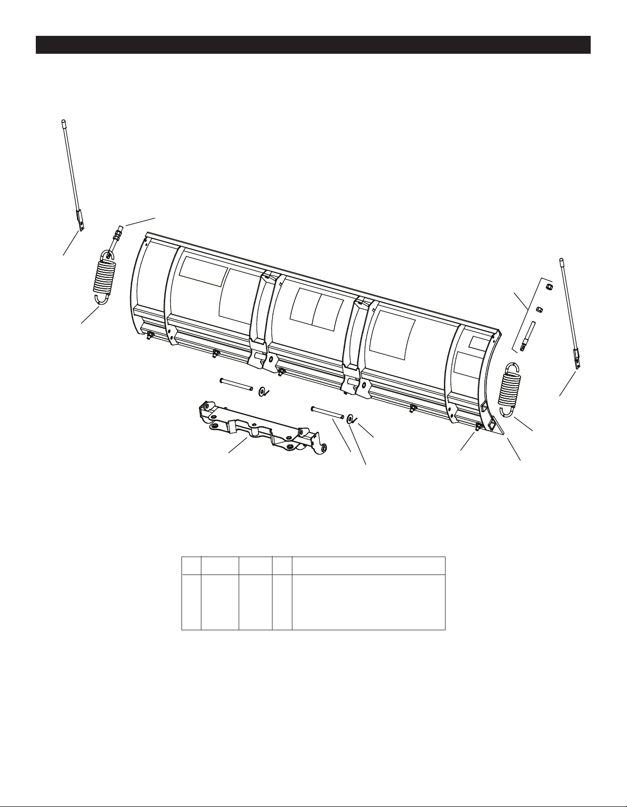
42 12978 12978 2 •• Trip Spring
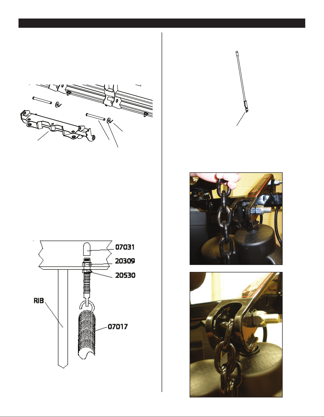
09917 09917 1 •• Plow Marker Kit
43 08214 08214 2 ••• Plow Marker
44 20027 20027 4 ••• Bolt H 5/16-18 x 1 Gr. 2
45 20304 20304 4 ••• Locknut 5/16-18
46 20352 20352 8 ••• Flatwasher 5/16”
47 15372 15372 1 •• Starter Solenoid - 12 volt
48 21832 21832 1 •• Split Bushing
49 23047 23047 1 •• Controller
50 23059 23059 1 •• Truck Side Harness
41102 41102 1 •• Hardware Bag
51 09124 09124 2 ••• Eye Bolt
52 20357 20357 2 ••• Flatwasher 5/8”
53 20385 20385 2 ••• Cotter Pin 1/8 x 1-1/4”
54 22989 22989 2 ••• Pivot Pin 5/8 x 5-3/4”
55 20357 20357 2 ••• Flatwasher 5/8”
56 22686 22686 2 ••• Trip Bumper
57 15187 15187 1 • Breather
58 23057 23057 1 • T-Connector
59 07810 07810 1 • Light Set Nite Saber 3
60 14065 14065 1 • Dp Std Caster Kit
61 08571 08571 1 •• Hdwe Bag Hairpin Cotter
62 14062 14062 3 ••lm Xl Caster Assy
Parts List
Meyer Products LLC reserves the right, under its continuing product
improvement program, to change construction or design details,
specifications and prices without notice or without incurring any
obligation.
Parts indented are included in the carton, bag or assembly under which they are indented.
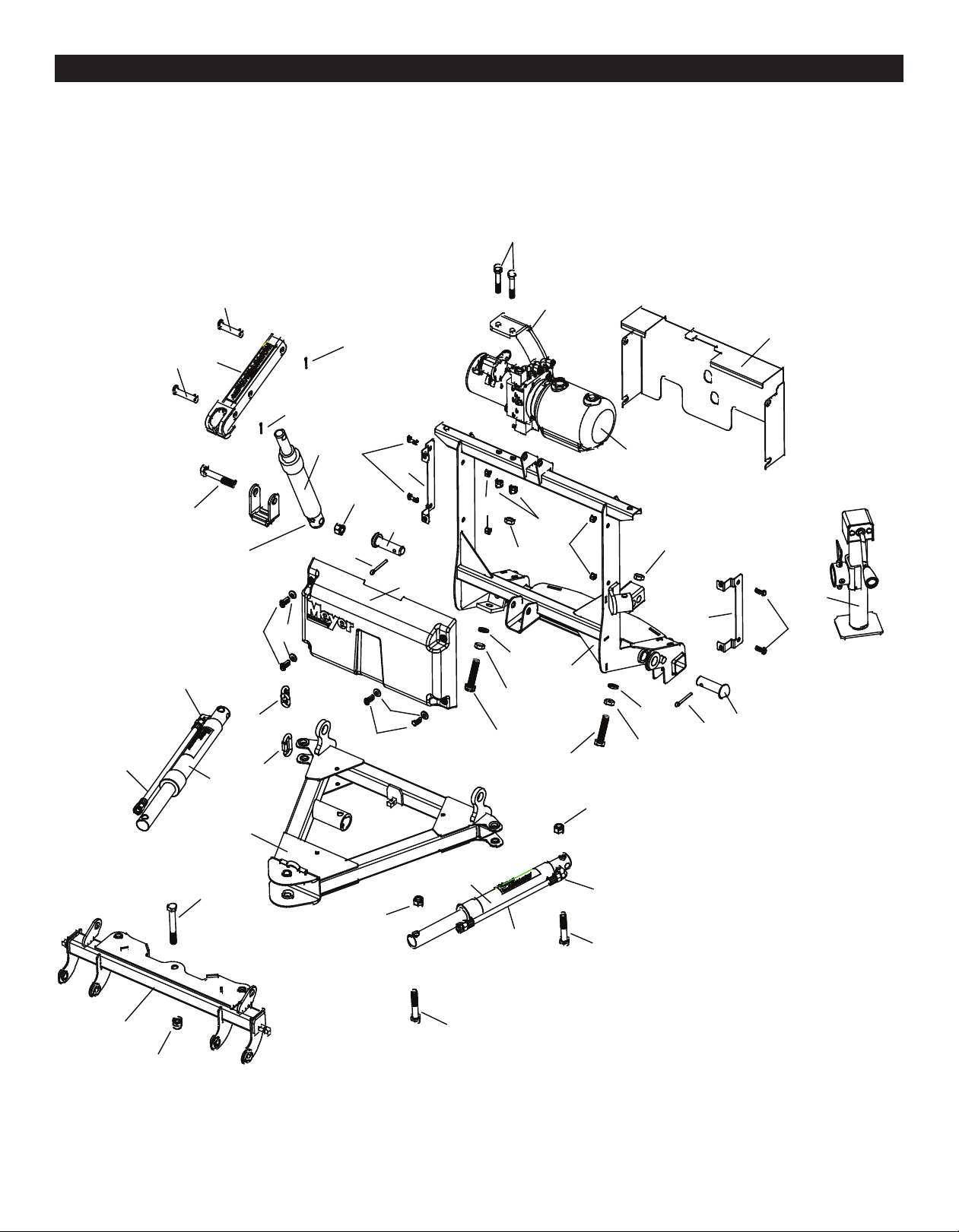
28300 & 28310 E-73 EZ Build
Item Part No. Part No. Qty. Description
28300 --------- 1 WM 6.8 2” Rec E-73 DP Mount Assy.
--------- 28310 1 WM 7.6 2” Rec E-73 DP Mount Assy.
1 05888 05888 1 • Lift Ram 1-1/2 x 8”
07772 07772 1 • LH Ram with Hose & Fittings
2 05887 05887 1 •• Ram (1-1/2” x 10”)
3 22866 22866 1 •• SAE 6 x 90 Degree Elbow
4 22885 22885 1 •• Hose Assy 1/4 x 54” M-6
07783 07783 1 • RH Ram with Hose & Fittings
2 05887 05887 1 •• Ram (1-1/2” x 10”)
3 22866 22866 1 •• SAE 6 x 90 Degree Elbow
4 22921 22921 1 •• Hose Assy 1/4 x 38” M-6
5 10514 10514 1 • Lift Arm
6 14250 14250 1 • Pivot Bar Drive Pro 6.8
7 14185 14185 1 • E-73 DP Mounting Bracket
8 14232 14232 1 • A-Frame Drive Pro
9 14289 14289 1 • E-73 Lift Unit Cover Front
10 14288 14288 1 • E-73 Lift Unit Cover Rear
11 14290 14290 2 • Lift Unit Cover Bracket
12 16027 16027 1 • E-73 Lift Ass’y. (Unit only)
13 18926 18926 1 • Lift Frame
14 20146 20146 1 • Bolt H 5/8 - 11 x 3-1/4” Gr. 5
15 20147 20147 4 • Bolt H 5/8 - 11 x 3-1/2” Gr. 5
16 20309 20309 6 • Locknut 5/8 - 11
17 20331 20331 2 • Lockwasher 5/8”
18 20357 20357 2 • Flatwasher 5/8”
19 20385 20385 2 • Cotter Pin 1/8 x 1-1/4”
20 22845 22845 1 • Hair Pin
21 20420 20420 2 • Cotter Pin 1/4 x 2”
22 22000 22000 1 • Bolt H 5/8-11 x 4-1/2” Gr. 8
23 22022 22022 1 • Crankstand
24 22436 22436 2 • Pin 1 x 3”
25 23023 23023 1 • Plow Side Harness
26 22719 22719 2 • Pivot Pin 5/8 x 3”
27 22866 22866 1 • SAE Mx3/8 90 Degree Elbow
28 22884 22884 1 • Hose 1/4 x 33”
29 20027 20027 4 • Bolt H 5/16-18 x 1” Gr. 2
30 20049 20049 4 • Bolt H 3/8-16 x 1 Gr. 2
31 20100 20100 2 • Bolt H 1/2-13 x 2-3/4” Gr. 5
32 20305 20305 4 • Locknut 3/8-16
33 20307 20307 2 • Locknut 1/2-13
34 8501003013 8501003013 4 • 5/8-11 Finish Nut
35 20800 20800 1 • Quick Link 5/16”
36 21543 21543 1 • Chain 5/16” x 29”
37 11101 11101 1 • Hinge Pin
38 22083 22083 1 • Lynch Pin
39 20352 20352 4 • Flatwasher 5/16”
40 8500003307001 8500003307001 2 • Bolt H 5/8-11 x 3” Gr. 5
(2)
Parts Diagram

28300 and 28310 E-73 Assembly
(3)
1
2
3
4
5
6
7
8
9
10
23
4
11
12
13
14
15
16
17
19
20
11
15
16
16
16
17
21
21
22
23
24
26
27 & 28
29
30
24
26
29
30
31
32 33
34
35
36
39
40
32 34
34
34
39
40

WM 6’-8” WM 7’-6”
Item Part No. Part No. Qty. Description
09478 09479 Drive ProTM Moldboard Assembly
59 09276 09796 1 • Cutting Edge
60 --------- 22067 8 • Bolt 1/2-13 x 3-1/4” Gr. 5
61 22067 --------- 6 • Bolt 1/2-13 x 3-1/4” Gr. 5
62 20307 20307 8 • Locknut 1/2-13
WM 6’-8” & 7’-6”Parts List
Parts indented are included in the assembly under which they are indented.
MeyerProductsLLCreservestheright,underitscontinuingproductimprovement
program,tochangeconstructionordesigndetails,specicationsandpriceswithout
notice or without incurring any obligation.
(4)
WM 6’8” and WM 7’6” Assembly
59
60-62
6
51
52
53
54
43-46
43-46
51
42
42

Attaching Plow to EZ Build Assembly
A. Liberally coat Pivot Pins (54) with Coolube Multi-Purpose Premium Grease
Part No. 15181.
B. Attach Pivot Bar (6) to Moldboard with Pivot Pins (54), 5/8”atwashers (52)
and insert Cotter Pins (53).
E. Attach Plow Markers (43) to moldboard using 5/16-18 x 1” Bolt (44), 5/16”
Flatwasher (46) and 5/16-18 Locknut (45)
F. Attach the Lift Chain to the Lift Arm (5) through the two hooks on the lift
arm. Adjust the lift chain at the lift arm so that there are 2-3 links of slack.
This ensures that the plow blade will lift fully and be able to follow the
ground contour while plowing.
(5)
C. Attach Eye Bolts (51) to Moldboard and Trip Springs (42) to Pivot Bar (6),
making certain locknuts are positioned as shown below.
D. Make certain each Eye Bolt (51) is in a vertical position as shown below so
that the Eye Bolt (51) and Trip Spring (42) hinge properly when moldboard
trips.
Note: Proper tension is attained when Trip Spring (42) coils just begin to separate
and then tightening top locknut four additional turns. Tighten bottom Locknut
(20530) to secure Eyebolt in position. Install Eyebolt caps (07031) over exposed
threads.
59
60-62
6
51
52
53
54
43-46
43-46
51
42
42
59
60-62
6
51
52
53
54
43-46
43-46
51
42
42

(6)
Vehicle Side Wiring Diagram
G. Run Truck Side Control Harness (50) through a hole in grille and into the
engine compartment.
Secure Truck Side Control Harness (50) from any hot or
moving parts with tie wraps as needed.
H. Drill a 1-1/4” Diameter Hole through rewall to install split bushing (48)
and extend the harness into the cab of the vehicle.
I. Run trailer end of Truck Side Control Harness to the back of the vehicle
and plug into at 4 pin trailer connector on vehicle. Be sure to add
dielectric grease to the plug connection.
J. Route Power harness through grille of vehicle and connect red to (positive
post) and black wire to (negative post) of vehicle battery.
Top o the unit to the ll line on the reservoir with Meyer M-1 Hydraulic Fluid.
NOTE: Proper uid level is to the ll line on the reservoir for the E-73.
It must be checked with the lift cylinder fully retracted.
For snow plow light installation see separate instructions.
Connect both male ends from the snow plow light to the female ends on the
Plow Side Harness (25).
Check snow plow light blinkers to make sure the wires have not been reversed.
Note: All electrical connections should have both ends coated with a dielectric
grease, Meyer Part No. 15632, prior to nal installation. This will ensure a good
connection and help in preventing corrosion.
K. Refer to Operation and Maintenance Manual for complete controller
operation.
Hydraulic Solenoid Color Code:
OPERATION - SOLENOID COMBINATION
RAISE - Motor Solenoid + “B” Solenoid
LOWER - “A”Solenoid Only
LEFT ANGLE - Motor Solenoid Only
RIGHT ANGLE - Motor Solenoid + “C”Solenoid
COIL COLOR CODE
MOTOR SOLENOID - WHITE WIRE
“A” - BLACK WIRE
“B” - RED WIRE
“C” - GREEN WIRE
GROUND WIRE EACH COIL BLACK W/WHITE STRIPE
M. Assemble adjustable stacking stop bolts to lift frame (13) using 5/8-11 x
2-3/4” bolts (40), lockwashers (17) and jamnuts (34). See below.
Note: Adjustment must be made after moldboard assembly is installed.
Adjustment bolts (40) should make contact with the a-frame before any
part of the A-Frame/ Sector or moldboard come in contact with the lift
arm and, or hydraulic unit while raising the snowplow or stacking snow.
Moldboard should be checked in all positions.
1) Route into vehicle’s cab and plug into controller.
2) Route to the front of the vehicle and plug into the plow
side harness.
3) Route to rear of vehicle and plug into vehicle’s trailer
harness using the trailer adapter harness (54).
4) BLUE will connect to the vehicle’s keyed accessory
circuit.
5) White wire will connect to 2015 & Later GM vehicles with
alternator relay. See Meyer Products Service Bulletin SB252.
The following two steps are optional and may be enforced
by local law which requires your vehicle lights to be o
while your plow lights are on and vice versa.
6) Connect the RED to the HIGH beam function.
7) Connect the WHITE to the LOW beam function.

Mount Plow To Vehicle
For Mounting and Dis-mounting instructional video’s please visit www.youtube.com/meyerproducts
(7)
Meyer Products assumes no responsibility for installations not made in
accordance with these instructions.
6. Remove weather covers and connect
both electrical plugs.
WingMan 2" Receiver Mounting System – Mount/ON
2. Install receiver hitch pin and hair pin.
2
3
4. Remove crankstand from a-frame.
4
1.
Pull vehicle into plow assembly and push plow assembly forward an
inch or two.
1
5. Attach crankstand to lift frame.
5 6
3. Adjust crankstand until until it is no longer in contact with the ground.
6. Remove weather covers and connect
both electrical plugs.

Dis-Mount Plow From Vehicle
For Mounting and Dis-mounting instructional video’s please visit www.youtube.com/meyerproducts
Meyer Products assumes no responsibility for installations not made in
accordance with these instructions. (8)
WingMan 2" Receiver Mounting System – Dismount/OFF
1. Press down button until Float light turns Blue/on.
1
4. Attach crankstand to a-frame..
4
5. Adjust crankstand until crankstand comes into
contact with the ground and then turn 1 to 2
revolutions.
5
8. Back vehicle away from plow assembly.
8
3
3. Remove crankstand from lift frame.
6. Remove hair pin and pull out receiver hitch pin.
6
2. Push lift arm down until there is a little slack in the chain.
2
7. Disconnect both electrical plugs and install weather cover
on both ends.
7
8

(9)
Please visit http://www.meyerproducts.com/plows/lotpro.aspx for a complete listing of accessories
Meyer Products LLC
18513 Euclid Ave. • Cleveland, Ohio 44112-1084
Phone 216-486-1313
Please visit http://www.meyerproducts.com/plows/lotpro.aspx for a complete listing of accessories
E-73 Wire and Hose Locations
“A”Valve Black & Black
with White Stripe
“B”Valve Red & Black
with White Stripe
“C”Valve Green & Black
with White Stripe
Left Angle Cylinder
Right Angle Cylinder
Lift Cylinder
Motor Solenoid White
Motor Solenoid Purple
E-73 Drop Speed Adjustment: Loosen jam nut and turn knob clockwise to slow the drop of the plow and
counter clockwise to speed the drop of the plow. Tighten jam nut.
E-73 Drop Speed Adjustment
Drop Speed Adjustment
To Plow Lights
To Vehicle Harness
Purple, Blue, and Yellow
wire sets are not used

PRE-DELIVERY INSPECTION
Vehicle Make: Vehicle Model:
Vehicle Year: Vehicle VIN#:
Vehicle FGAWR: Installing Company:
Mounting Type: Plow Type:
WingMan 6.8 7.6
Hydraulic Serial Number: Moldboard Serial Number:
Comments:
Inspected By: W.O.# Date:
Customer Signature:
All bolts torqued to specication
Suspension interference
2” Receiver height in inches
Trip springs adjusted
Lift Chain Adjusted
Check for hydraulic uid leaks
Hydraulic uid Level
Dielectric grease applied to ALL electrical connection
All wires/modules secured
Plow Stops Adjusted (plow cannot bump hyd. unit)
Controller Operation
Plow Operation Up
Plow Operation Left
Plow Operation Right
Plow Operation Down
Plow Light Blinker Left & Right Operation
Plow Light Low & High Beam Operation
Plow Lights Adjusted
Plow Mount/Dismount reviewed with Customer
Plow Operation reviewed with Customer
Warranty/Registration/Owners Manual
reviewed with Customer
(10)
Serial Number Decal Locations
Moldboardserialnumberisattachedtothe
back of the moldboard.
E-73 unit serial number is
under the cover attached to the
hydraulic unit.
This manual suits for next models
1
Table of contents
Other Meyer Snow Blower manuals

Meyer
Meyer Super-V3 User manual

Meyer
Meyer power box 810 User manual

Meyer
Meyer Diamond MD II User manual

Meyer
Meyer V-66 QUIK LIFT User manual

Meyer
Meyer Path Pro2 Guide

Meyer
Meyer 51200 Super V LD Instruction Manual

Meyer
Meyer Drive Pro LD Guide

Meyer
Meyer LotPro 41325 Instruction Manual

Meyer
Meyer EZ-MOUNT XPRESS AG-7.5 User manual