9
CHAPTER 2: CONNECTING STELLA LOUDSPEAKERS
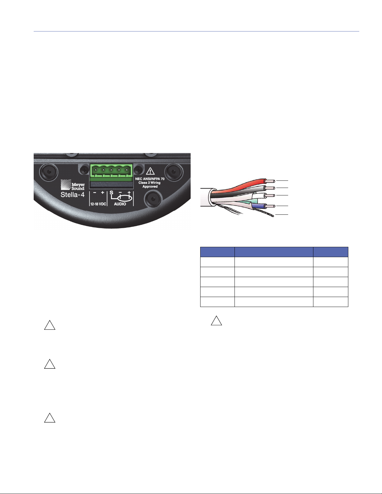
STELLA CONNECTOR
Stella loudspeakers receive DC power and balanced audio
from a five-pin Phoenix connector on their rear panel. The
connector’s five pins include two for DC power (negative
and positive) and three for balanced audio (shield, negative,
and positive). These pins are clearly labeled on the Stella
rear panel. The connector accepts conductors up to
12 AWG (American Wire Gauge) or 2.5 mm2. To function
properly, Stella loudspeakers require DC power in the range
of 12–18 V DC.
A single composite cable (such as Belden 1502R) wired for
both DC power and balanced audio can connect each Stella
loudspeakers to one of the Stella-188’s eight Channel Out-
puts.
Each Stella loudspeaker comes with one Phoenix cable
connector for making loudspeaker cables. For information
on cable requirements, see “Cable Lengths and Cable
Gauges for Stella Loudspeakers” on page 14.
CAUTION: Do not connect Stella loudspeakers
to voltages above 18 V DC. Receiving voltages
above 18 V DC will permanently damage Stella loud-
speakers.
CAUTION: For installations comprising both
Stella loudspeakers and 48 V DC loudspeak-
ers, make sure that Stella loudspeakers are only con-
nected to a Stella-188 power supply. Connecting
Stella loudspeakers to a 48 V DC power supply will
permanently damage the Stella loudspeakers.
CAUTION: When wiring Stella loudspeaker
cables, make sure each pin in the connector is
wired correctly to avoid damage to the loudspeaker
and polarity reversal, which can affect system perfor-
mance.
Wiring Stella Loudspeaker Cables with
Belden 1502 Cable (or Equivalent)
The most convenient method of wiring Stella loudspeaker
cables is with a multiconductor cable such as Belden 1502,
which has dedicated conductors for DC power and bal-
anced audio in a single jacket. When wiring Stella loud-
speaker cables with Belden 1502, use the conventions in
Table 1. The red and black wires are 18 AWG, thicker than
the other three wires, and should be used for DC power (for
maximum cable lengths, see “Cable Lengths and Cable
Gauges for Stella Loudspeakers” on page 14). The blue,
white, and shield drain wires are shielded together and
should be used for audio.
CAUTION: When wiring Stella loudspeaker
cables, it is extremely important that each pin
be wired correctly. Make sure the DC from the exter-
nal power supply is wired directly (and only) to the DC
pins on the Stella loudspeaker connector, and that
the polarity is observed (negative to negative, positive
to positive) to avoid damage to the loudspeaker. In
addition, make sure that audio pins are wired cor-
rectly; polarity reversals for audio signals affect sys-
tem performance.
Stella Connector
Belden 1502 Composite Cable
Table 1: Wiring Stella Loudspeaker Cables with Belden 1502R
Wire Signal Gauge
Red DC power, positive (+) 18 AWG
Black DC power, negative (–) 18 AWG
White Balanced audio, positive (+) 22 AWG
Blue Balanced audio, negative (–) 22 AWG
Shield drain Balanced audio, shield 24 AWG
Red: DC power (+)
Black: DC power (–)
White: audio (+)
Blue: audio (–)
Shield drain: audio shield