Meyrat MHF-22 User manual

Version: 18/10/2016
Filename: NA-MHF-22-COD-E_version3.doc
© Meyrat SA 2017 1 / 25
MEYRAT SA
Lengnaustrasse 10, CH-2504 Biel-Bienne, Switzerland
+41(0) 32 344 70 20 +41(0) 32 344 70 29
E-Mail: sav@meyrat.com
www.meyrat.com
MHF-22 spindle
(Art.-N° 010-21-00-COD, 010-21-50-COD, 010-22-00-COD, 010-22-50-COD, 010-23-00-COD
010-23-50-COD, 010-24-00-COD, 010-24-50-COD, 010-32-50-COD, 010-36-50-COD)
Assembly Instructions
(NA-MHF-22-COD-E)

Version: 18/10/2016
Filename: NA-MHF-22-COD-E_version3.doc
© Meyrat SA 2017 2 / 25
TABLE OF CONTENTS
1Introduction...................................................................................................................................... 3
1.1 Identification............................................................................................................................. 3
1.2 Intended users and objectives of these assembly instructions ............................................... 3
1.3 Directions for using the assembly instructions ........................................................................ 3
2Technical characteristics .................................................................................................................5
2.1 Electric spindle......................................................................................................................... 5
2.2 Bearings lubrication type ......................................................................................................... 6
Grease............................................................................................................................................. 6
Oil-mist Lubrication.......................................................................................................................... 6
Air-oil lubrication .............................................................................................................................. 7
2.3 Frequency converter................................................................................................................ 7
3Spindle drawing ............................................................................................................................... 8
3.1 « MHF-22 ER8/60 COD » and « MHF-22 ER8/80 COD » spindles........................................ 8
010-21-00-COD / 010-22-00-COD .................................................................................................. 8
010-21-50-COD / 010-22-50-COD .................................................................................................. 8
010-23-00-COD / 010-24-00-COD .................................................................................................. 9
010-23-50-COD / 010-24-50-COD .................................................................................................. 9
3.2 « MHF-22 ER8/60 COD » front connection........................................................................... 10
010-32-50-COD............................................................................................................................. 10
010-36-50-COD............................................................................................................................. 10
3.3 Electrical connector, pneumatic tube and radius of curvature............................................... 11
4Safety notice..................................................................................................................................12
4.1 General.................................................................................................................................. 12
4.2 Appropriate field of application .............................................................................................. 12
4.3 Safety analysis for incorporation of spindle........................................................................... 13
4.4 Organisational issues ............................................................................................................ 14
4.5 Specific product dangers....................................................................................................... 14
4.6 Additional dangers................................................................................................................. 15
4.7 Environmental protection....................................................................................................... 15
5Description of the product.............................................................................................................. 16
5.1 Operation............................................................................................................................... 16
5.2 Field of application................................................................................................................. 16
5.3 Scope of standard delivery.................................................................................................... 16
5.4 Dangerous parts and safety features .................................................................................... 16
5.5 Clamps and tools................................................................................................................... 17
6Installation and activation ..............................................................................................................18
6.1 Safety during installation and activation................................................................................ 18
6.2 Preliminary work .................................................................................................................... 18
Delivery.......................................................................................................................................... 18
Peripheral devices ......................................................................................................................... 18
6.3 Spindle assembly................................................................................................................... 19
Safety............................................................................................................................................. 19
Mounting position........................................................................................................................... 19
Preparation for assembly............................................................................................................... 19
6.4 Connection operation............................................................................................................. 20
Connections for overpressure of lifetime lubricated spindles........................................................ 20
Graph for the settings of the pressure P1 depending on the tube length and diameter. .............. 20
Connections for oil-mist lubrication................................................................................................ 21
Graph for the settings of the pressure P1 depending on the tube length and diameter. .............. 21
Connections for air-oil lubrication .................................................................................................. 22
6.5 First starting of spindle........................................................................................................... 23
6.6 Daily use................................................................................................................................ 24

Version: 18/10/2016
Filename: NA-MHF-22-COD-E_version3.doc
© Meyrat SA 2017 3 / 25
1 Introduction
These assembly instructions describe your electric spindle. It has been manufactured according to the
most advanced technology and according to recognised safety regulations.
Improper use or misuse of the spindle or commissioning of the machine without following the
instructions for use of this assembly instruction excludes a guarantee from MEYRAT SA.
The assembly instructions must therefore be read and understood by all persons who will be dealing
with the electric spindle.
1.1 Identification
Your electric spindle is identified as follows:
Item no.: ___________________________
Serial number: ___________________________
Year of manufacture: ___________________________
1.2 Intended users and objectives of these assembly instructions
Intended users
These assembly instructions are intended for:
- Assembly personnel (mechanics, electricians, electronics specialists) at the location of the
constructor of the machine.
- Operators of the machine at the customer’s location.
- Service technicians at the client’s location
It is presumed that the following qualifications have been acquired:
- Mechanical work: training as a skilled mechanic (or equivalent training)
- Electrical work: training as a skilled electrician or electronics specialist (or equivalent training).
- Maintenance technician: training as a skilled mechanic (or equivalent training)
In addition, it is presumed that these persons have basic knowledge in the handling of electric
spindles.
Objectives of these assembly instructions
These assembly instructions should allow all intended users to perform their work reliably and
professionally. These instructions must therefore be read and understood by all persons responsible
for work on or relating to the electric spindle.
1.3 Directions for using the assembly instructions
Organisation and handling of the service instruction manual
In the assembly instructions you will find instructions concerning the assembly, installation, operation,
maintenance, and troubleshooting of your electric spindle, supplemented as necessary with notes on
safety and danger.
Instructions on the assembly and installation of peripheral devices are not included in the assembly
instructions. These data are found in the corresponding documentation on these peripheral devices.

Version: 18/10/2016
Filename: NA-MHF-22-COD-E_version3.doc
© Meyrat SA 2017 4 / 25
Any person responsible for work on or relating to the spindle must have read and understood all the
chapters relating to the work to be performed, before beginning any work. In particular, the safety and
danger notices must be read and understood.
Additionally, please note:
- The instructions and notices in the documentation on the peripheral devices.
- All local safety precautions
Icons
Note
This icon is placed beside all important notices providing information on the professional
and efficient use of the product.
!
This icon, accompanied by the indication “DANGER!” at the beginning of the text, is
placed beside all indications having to do with safety or the risk of danger to which the
user or a third party could be exposed in case of non-compliance with the
indication.
!
This icon, accompanied by the indication “ATTENTION!” at the beginning of the text, is
placed beside all indications having to do with safety or the risk of danger, which could
cause damage to the spindle or other objects in case of non-compliance with the
indication.
- Manipulations requiring several steps for completion are numbered.
Storage
Always keep these assembly instructions (including the documentation on the peripheral devices) near
the corresponding machine so that it will always be close at hand.
In case of loss of the service instruction manual, contact Meyrat SA and you will be able to obtain a
new copy for a fee. To this end, send a fax, indicating the serial number of the spindle, to:
MEYRAT SA
SAV
Lengnaustrasse 10
2504 Biel- Bienne
Switzerland
Tél. +41 32 344 70 20
Fax +41 32 344 70 29
Suggestions and proposals for changes
We are always grateful for you suggestions and proposals for improving this manual. If you would like
to submit your suggestions or proposals to us, please proceed as follows:
1. Make a copy of the corresponding page(s) and indicate your suggestions or proposals on the
copy.
2. Send these sheets indicating your name and address (including telephone and fax numbers)
to:
MEYRAT SA
SAV
Lengnaustrasse 10
2504 Biel- Bienne
Switzerland
Tél. +41 32 344 70 20
Fax +41 32 344 70 29
Version: 18/10/2016
Filename: NA-MHF-22-COD-E_version3.doc
© Meyrat SA 2017 5 / 25
2 Technical characteristics
2.1 Electric spindle
MHF-22 ER8/60 COD
Item No.
010-21-00-
COD
010-21-50-
COD
010-23-00-
COD
010-23-50-
COD
Min. rotation speed
5'000 min-1
Max. rotation speed
60'000 min-1
Continuous power
120 W
Connection
Axial
Radial
Axial
Radial
Type of tool clamp
ER8 - UP
Clamping capacity
ø 0.5 to ø 5.0
Bearing lubrication
Grease
Weight
0.15 to 0.2 kg
Accessories delivered
with the electric spindle
1 clamping nut ESP-ER8MS
1 wrench CSP-E8MS
1 wrench CLE-SW7-SW9
MHF-22 ER8/60 COD
Item No.
010-32-50-COD
010-36-50-COD
Min. rotation speed
5'000 min-1
Max. rotation speed
60'000 min-1
Continuous power
120 W
Connection
Radial, front connection
Type of tool clamp
ER8 - UP
Clamping capacity
ø 0.5 to ø 5.0
Bearing lubrication
Grease
Weight
0.22 to 0.4 kg
Accessories delivered
with the electric spindle
1 clamping nut ESP-ER8MS
1 wrench CSP-E8MS
1 wrench CLE-MHF22-00
MHF-22 ER8/80 COD
Item No.
010-22-00-
COD
010-22-50-
COD
010-24-00-
COD
010-24-50-
COD
Min. rotation speed
5'000 min-1
Max. rotation speed
80'000 min-1
Continuous power
160 W
Connection
Axial
Radial
Axial
Radial
Type of tool clamp
ER8 - UP
Clamping capacity
ø 0.5 to ø 5.0
Bearing lubrication
Air-oil
Weight
0.15 to 0.2 kg
Accessories delivered
with the electric spindle
1 clamping nut ESP-ER8MS
1 wrench CSP-E8MS
1 wrench CLE-SW7-SW9
!
ATTENTION! Use only a CFB-MHF500 type converter to drive an MHF-22 electric
spindle. A converter can only power one electric spindle at a time. Non-compliance with
the above indications can cause damage to the spindle and/or the frequency converter.
Version: 18/10/2016
Filename: NA-MHF-22-COD-E_version3.doc
© Meyrat SA 2017 6 / 25
2.2 Bearings lubrication type
The table below shows the lubrication for each spindle, depending its item number.
Item No.
Oil-mist *
Air-oil *
Grease
010-21-00-COD
x
010-21-50-COD
x
010-22-00-COD
x
x
010-22-50-COD
x
x
010-23-00-COD
x
010-23-50-COD
x
010-24-00-COD
x
x
010-24-50-COD
x
x
010-32-50-COD
x
010-36-50-COD
x
* The oil-mist lubrication and air-oil lubrication are similar regarding the functioning of spindle. So the
choice depends mainly on the machine on which the spindle is mounted.
!
ATTENTION! Failure to observe the type of bearing lubrication can cause rapid damage
to the spindle.
Grease
For spindles of this type, there is no provision for external lubrication. The bearings are permanently
lubricated for the life time of the electric spindle. Air overpressure inside the spindle prevents the
infiltration of impurities.
The required quality of the air is given by: DIN ISO 8573.1:2001 Class 3.
The air pressure should be 0.6 to 0.7 bar at the entrance of the spindle.
!
ATTENTION! A greater pressure can cause damage to the spindle.
Oil-mist Lubrication
Item no. :
DLB-MHF
Pressure at the entrance of spindle
1.6-1.7 bar
Pressure of manometer
According to chapter 6.4
Air quality
DIN ISO 8573.1:2001 Class 3
Oil
Motorex COREX HLP ISO VG 32
Regulation of oil flow
30 drops per minute
Accessories included with the group
1 liter of Motorex COREX HLP ISO VG 32
Pneumatic tube
ø6/4, length 2m to 10m *
* The first 10 cm of tube are ø4/2.5. The length of 10 cm should not be exceeded.
!
ATTENTION! Without a right lubrication, the spindle will be damaged very fast. It is best
to use a coil at the proximity of spindle; to create an oil reserve in case of pressure is
disabled.
!
ATTENTION! This kind of lubrication requires a stable and continuous in time functioning
to establish a steady oil flow in the tube. Thus, frequent interruptions of lubrication and air
pressure are not allowed. Lubrication must be active during periods of at least 1 hour.
!
ATTENTION! Only one spindle can be connected to each oil mist lubricator. With multiple
connections, it is not possible to guarantee the quality or quantity of lubrication on each
spindle.
DLB-MHF lubricators are available with different options, defined with a suffix as follows:
- DLB-MHF: Basic version (with air filter and lubrication unit).
- DLB-MHF-C: Electronic monitoring of air pressure and oil level.
- DLB-MHF-CEVII: Electronic monitoring of air pressure and oil level, solenoid valve at the air inlet.
- DLB-MHF-AD: additional lubrication unit for DLB-MHF-CEVII
For settings and connections on the units mist lubrication, please refer to the assembly instructions of
the device.
Version: 18/10/2016
Filename: NA-MHF-22-COD-E_version3.doc
© Meyrat SA 2017 7 / 25
Air-oil lubrication
Item no. of unit
Item no. of doser unit
DLB-SF3BNCDA
DLB-AVx
Pressure in spindle entry
0.6 to 0.7 bar
Air quality
DIN ISO 8573.1:2001 Class 3
Oil
Motorex COREX HLP ISO VG 68
Regulation of oil flow
30mm3per hour
Recommended volume of doser
10 mm3
Pneumatic tube
ø6/4, length 2m to 5m *
Accessories included with the group
4 liters of Motorex COREX HLP ISO VG 68
* The first 10 cm of tube are ø4/2.5. The length of 10 cm should not be exceeded.
!
ATTENTION! Without a right lubrication, the spindle will be damaged very fast. It is better
to use a coil at the proximity of spindle; to create an oil reserve in case of pressure is
disabled.
!
ATTENTION! The air pressure must be enabled / disabled at the same time that the
lubricants pump.
This kind of lubrication requires a stable and continuous in time functioning to establish a
steady oil flow in the tube. Thus, frequent interruptions of lubrication and air pressure are
not allowed. Lubrication must be active during periods of at least 1 hour.
!
ATTENTION! A too short length of tube will not allow the oil to create a continuous flow in
the tube. It will thus not be possible to guarantee a constant arrival of oil lubrication
between two pulses.
!
ATTENTION! Only one spindle can be connected to each doser output. With multiple
connections, it is not possible to guarantee the quality or quantity of lubrication on each
spindle.
For settings and connections on the air-oil lubrication units, please refer to the assembly instructions of
the device.
2.3 Frequency converter
Item no.:
CFB-MHF500
Interface
front panel / D-Sub 15 pins connector
Power supply
110-230 VAC
Dimensions (length x width x height)
220 x 105 x 105 mm
Weight
2.2 kg
!
ATTENTION! Before activating the frequency converter, read the assembly instructions.

Version: 18/10/2016
Filename: NA-MHF-22-COD-E_version3.doc
© Meyrat SA 2017 8 / 25
3 Spindle drawing
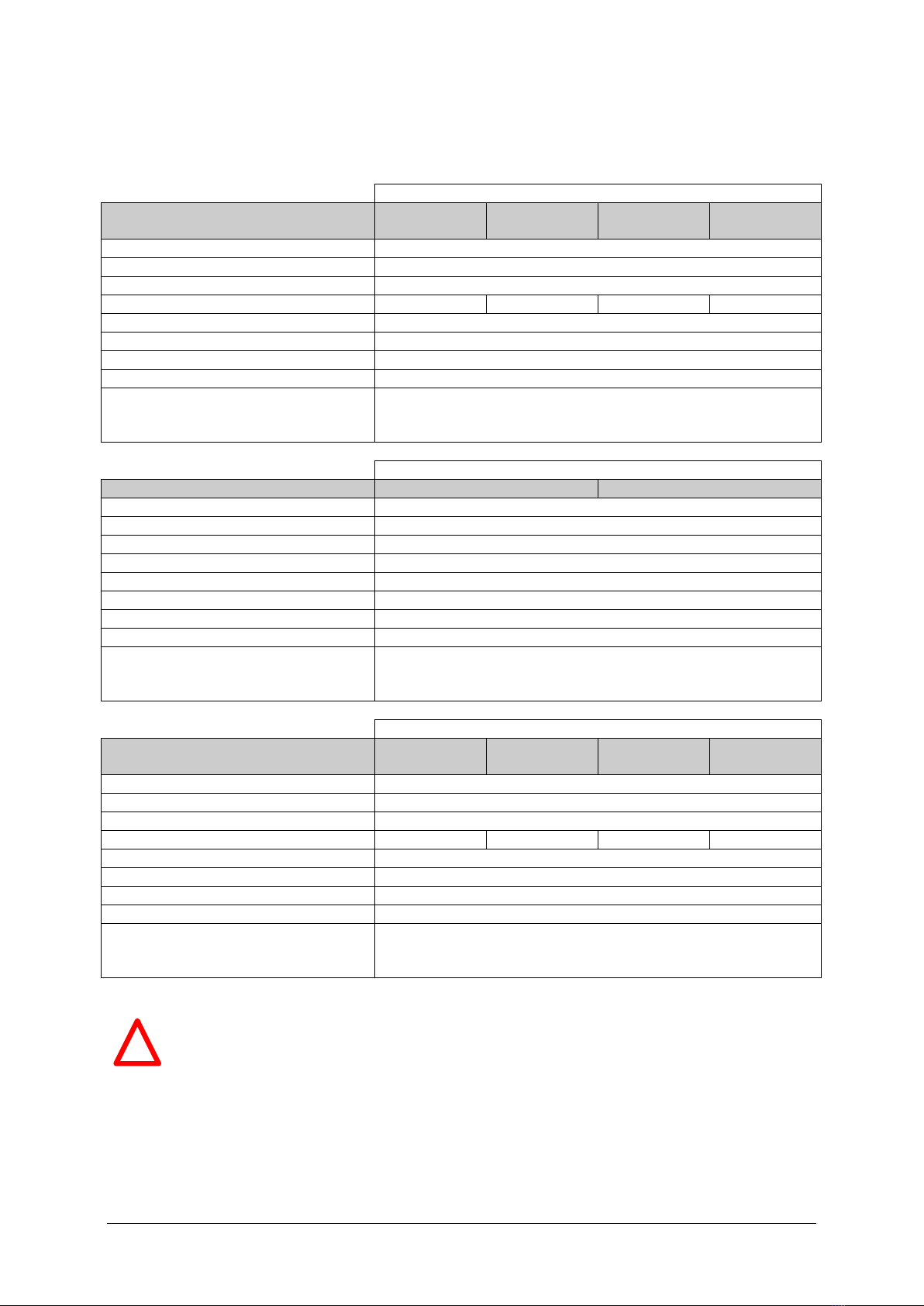
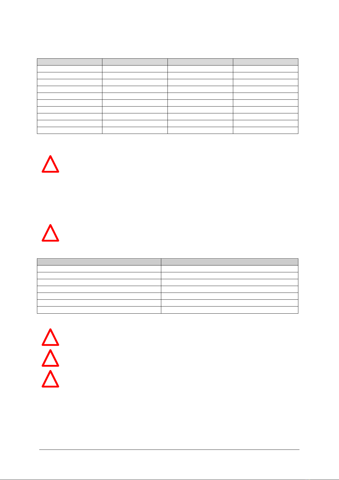
3.1 « MHF-22 ER8/60 COD » and « MHF-22 ER8/80 COD » spindles
010-21-00-COD / 010-22-00-COD
010-21-50-COD / 010-22-50-COD
Version: 18/10/2016
Filename: NA-MHF-22-COD-E_version3.doc
© Meyrat SA 2017 9 / 25
010-23-00-COD / 010-24-00-COD
010-23-50-COD / 010-24-50-COD

Version: 18/10/2016
Filename: NA-MHF-22-COD-E_version3.doc
© Meyrat SA 2017 10 / 25
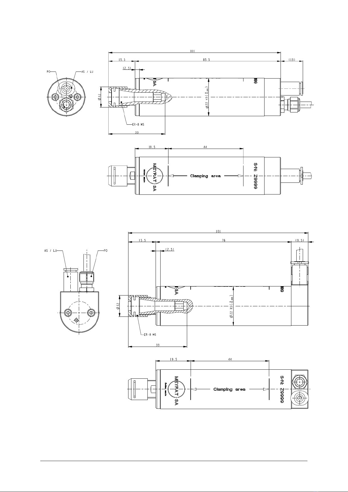
3.2 « MHF-22 ER8/60 COD » front connection
010-32-50-COD
010-36-50-COD
Version: 18/10/2016
Filename: NA-MHF-22-COD-E_version3.doc
© Meyrat SA 2017 11 / 25
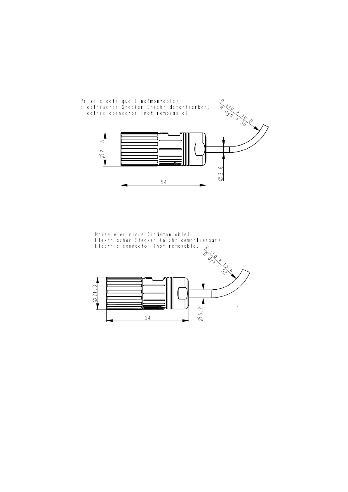
3.3 Electrical connector, pneumatic tube and radius of curvature
Electrical connector (rear connection)
Items : 010-21-00-COD, 010-21-50-COD, 010-22-00-COD, 010-22-50-COD, 010-23-00-COD,
010-23-50-COD, 010-24-00-COD, 010-24-50-COD
Electrical connector (front connection)
Items: 010-32-50-COD, 010-36-50-COD
Pneumatic tube
The radius of curvature of the pneumatic tube which is delivered with the spindle is at least 20 mm at
20°C.

Version: 18/10/2016
Filename: NA-MHF-22-COD-E_version3.doc
© Meyrat SA 2017 12 / 25
4 Safety notice
4.1 General
These assembly instructions contain basic instructions to follow during incorporation, starting and
maintenance. It is therefore essential to follow the detailed instructions in this chapter, but also the
special measures and recommendations which are given.
4.2 Appropriate field of application
The electric spindle is manufactured according to the most advanced technology and its use offers
total safety. It can, however, cause danger if it is not used in conformity with the precautions for use. It
has been constructed for high frequency machining in materials such as aluminium, cast iron, steel,
brass, titanium, synthetic materials, composite materials, graphite and wood. The following indications
for machining with high speed of rotation must absolutely be respected.
!
ATTENTION! To attain a long service life of the spindle the following indications must be
observed and respected. Non-compliance will shorten the service life of the spindle.
Basic indications
- Take into account the dynamic balancing of the cutting tools.
- Take into account the 0.01 mm maximum eccentricity, measured at the end of the tool.
- Assure a minimum resonance frequency for each tool by optimising the machining processes.
- Use cutting tools specifically designed for high speed machining.
- Use the shortest cutting tools possible.
- Make certain that the tools are well secured in the clamp.
- Make certain that the kind of tool holder corresponds to the spindle.
- Take into consideration the machining parameters for high speed machining, i.e. low-level
pass, rapid traverse and angling in two simultaneous axes.
- The permissible operating temperature is between 5°C and 40°C.
Any other use, as well as uses extending outside the cited cases is not authorised. MEYRAT SA
declines all responsibility for damages caused in these cases. The user alone takes responsibility for
the risk.

Version: 18/10/2016
Filename: NA-MHF-22-COD-E_version3.doc
© Meyrat SA 2017 13 / 25
Use in conformity with the precautions includes the following points;
- Compliance with the indications, precautions and notices in these assembly instructions on
this spindle.
- Compliance with the inspection and maintenance intervals.
- Maintaining the spindle in good condition.
- Use of the spindle observing the conditions prescribed regarding the environment and service.
!
DANGER! The spindle should not be used in the following circumstances:
- As a drive for a centrifuge or a fan.
- As a drive in general.
- Under water.
In case of use for the applications or in the circumstances listed above, it is to be expected that the
spindle will be destroyed or, due to the great centrifugal forces emanating from the high speed
rotations, that parts of the driven objects will become projectiles.
4.3 Safety analysis for incorporation of spindle
Before considering the assembly of the spindle, it is necessary to study the following points:
- Consider safety strategies that reduce the risk to an acceptable level.
- Define the required tasks for the foreseeable applications and assess the need for access and / or
approach.
-Identify sources of risks, including failures and failure modes associated with each task. Risks can
come from:
-The machine in which the spindle is integrated,
- Its association with other equipment,
-The interaction of people with the machine.
- Evaluate and assess the risks associated with the operation of the spindle:
-Risks of programming,
-Operational risks,
-Risks of use,
-Risks of maintenance.
-Choose methods of protection:
- The use of protective devices,
-The establishment of means of signalling,
-Compliance with safe working procedures.

Version: 18/10/2016
Filename: NA-MHF-22-COD-E_version3.doc
© Meyrat SA 2017 14 / 25
4.4 Organisational issues
The spindle can only be installed, activated, maintained and if necessary repaired by persons familiar
with this product and having the required qualifications. It is the responsibility of the client to make
certain that the assembly instructions are supplemented with internal directives concerning
supervision, obligation to report events, organisation of work, personnel qualifications, etc.
Competences for the various activities relating to installation and activation of the spindle must be
clearly defined and respected in order to prevent any lack of precision in these matters.
This is particularly applicable for work on the electrical and pneumatic equipment. This work must be
executed only by persons particularly trained for these tasks.
All persons responsible for work on the spindle must have read and understood these assembly
instructions.
In addition to the assembly instructions please observe the following:
- The safety and danger notices in the separate documentation for the peripheral devices.
- All local and generally applicable precautions relating to work safety, the prevention of
accidents and the environment.
Without written authorisation from MEYRAT SA, no additions or modifications can be undertaken on
the spindle or the peripheral devices.
To replace spindle components, use only original replacement parts and parts from MEYRAT SA.
4.5 Specific product dangers
!
DANGER! In spite of correct use of the spindle, there is still a risk of bodily harm or death
of the user or a third party, as well as a risk of damage to the spindle or other equipment.
Thus, the following precautions regarding safety and danger warnings must be respected
and observed when the electric spindle operates at very high speeds.
Under these conditions, it is possible that chips or parts of tools, in case of tool breakage,
will be ejected at high speeds. The following measures must be taken on machines where
the spindle is installed.
- The work area must be able to be enclosed in a cabin.
- The cabin door must be equipped with a control such that the start-up of the
spindle rotation is only possible if the door is closed.
- The cabin itself must be designed so that neither chips nor parts of tools can go
through the walls or windows/glass panels.
!
DANGER! Non-compliance with this precaution can lead to personal injury or death.

Version: 18/10/2016
Filename: NA-MHF-22-COD-E_version3.doc
© Meyrat SA 2017 15 / 25
4.6 Additional dangers
Electrical system
Work on the electrical system can be undertaken only by persons trained for this task and aware of
potential dangers. If work must be done on the devices while the electric power is on, additional
personnel must be present and prepared to take adequate measures in case of emergency.
Before undertaking work on the electrical system:
- The electric power should be cut off, thus rendering impossible an unpredictable re-
engagement of the machine or the peripheral devices.
- A waiting period to allow the necessary time for the discharge of the frequency converter must
be respected (see the assembly instructions for the frequency converter).
Pneumatic system
Work on the pneumatic system can be undertaken only by persons qualified and trained for this task.
Before undertaking work on the pneumatic system, it is necessary to disengage the machine and
render impossible an unpredictable re-engagement of the machine and, if need be, to do the same for
the pneumatic peripheral (close the valves). Next, it is necessary to de-pressurise the pneumatic
system (see the assembly instructions for the pneumatic peripheral).
Consumables
Consumables (oil and liquid coolant) can be dangerous to persons in several ways (allergic reactions,
danger of slipping on spilled or leaked product). Please handle these products with precaution and
observe the work safety procedures relating to them.
4.7 Environmental protection
The oils used in connection with the spindle can harm the environment if used incorrectly. Please treat
these substances with care and strictly obey all local rules and laws in effect.
Gather the used consumables in appropriate containers (for example the original containers) and
dispose of properly.

Version: 18/10/2016
Filename: NA-MHF-22-COD-E_version3.doc
© Meyrat SA 2017 16 / 25
5 Description of the product
5.1 Operation
The electric spindle is constructed as follows:
The synchronous motor drives the shaft of the spindle. The rotation speed is continuously regulated by
the frequency converter.
The shaft of the spindle is guided in the sleeve by two bearings stages. The bearings are lubricated
with grease or air-oil, according to the construction of the spindle.
The hybrid bearings of an air-oil spindle are lubricated with oil and compressed air. The lubricant is
directed at the surface of the ball bearings.
The oil reflux system expels the excess oil from the inside of the spindle. This reflux does not exist on
spindles lubricated with grease.
The air screen and special labyrinth system prevents the infiltration of impurities into the bearings.
!
ATTENTION! Without overpressure, the protection of spindle against the intrusion of
foreign bodies is not guaranteed. The intrusion of foreign bodies can destroy the spindle.
The tool clamping system is integrated in the shaft and is equipped with an ER8-UP tool attachment
clamp. The tools are secured with an ER8MS clamping nut.
5.2 Field of application
The electric spindle is used for:
High speed machining of materials such as: aluminium, cast iron, steel, brass, titanium, plastic
materials, composites, graphite and wood.
5.3 Scope of standard delivery
The scope of standard delivery includes:
- The spindle
- The assembly instructions
- The frequency converter
5.4 Dangerous parts and safety features
List of dangerous parts
The spindle contains the following dangerous parts:
- The rotating part of the spindle and the tool
- The interface between the spindle and the securing clamp.
- Electrical connections.
- Pneumatic connections.

Version: 18/10/2016
Filename: NA-MHF-22-COD-E_version3.doc
© Meyrat SA 2017 17 / 25
List of safety features
The peripheral devices and systems are ideally equipped with the following monitoring features:
In the air-oil lubrication system:
- Pressure monitoring
- Level monitoring.
In the frequency converter:
- See the instructions in the converter assembly instructions.
5.5 Clamps and tools
The following points must be observed regarding the clamps and tools used in conjunction with the
electric spindle:
Clamps
The attachment of the tool with the clamp and the clamping nut must be performed using the two
wrenches delivered with the electric spindle. The recommended torque is 5 Nm.
!
DANGER! The electric spindle must not be set in rotation without a tool in the clamp and
the clamp must be held in place by the clamp nut.
!
ATTENTION! Use only securing clamps designed for machining.
Tools
Maximum eccentricity of the tool: 0.01 mm.
!
DANGER! The clamps and tools which do not meet the above minimum requirements
must not be used:
- The clamps and tools must be individually submitted to centrifugal force
resistance tests according to DIN 8085.
- The maximum rotation speed must not be exceeded in any case.
Note
NOTE! When there is doubt regarding critical rotation speeds, MEYRAT SA can perform
the calculation for the tool attached to its spindle.

Version: 18/10/2016
Filename: NA-MHF-22-COD-E_version3.doc
© Meyrat SA 2017 18 / 25
6 Installation and activation
6.1 Safety during installation and activation
!
DANGER! The following safety measures and warnings must be strictly observed and
respected. Non-compliance can put persons in danger and/or damage equipment.
- The spindle can only be installed or activated by persons who are trained and
sufficiently qualified for the tasks envisaged.
- It is the responsibility of the client to take care that the competencies and the
qualification verification of persons implicated in the various activities relating to
the installation and activation are clearly defined and respected.
- All persons involved in the installation and activation of the spindles must have
read and understood the instructions in this manual.
- No modification or addition to the spindle or the peripheral devices delivered by
MEYRAT SA can be undertaken without written authorisation from MEYRAT SA.
- All the safety features must be linked to the controls of the machine according to
their function and cannot be short-circuited or removed.
6.2 Preliminary work
Before beginning the installation work, please check:
Delivery
- If it is complete and correct in conformity with the delivery note.
- If it has been damaged in transport (all damages must be reported to the carrier and to the
supplier within 10 days of the reception of the merchandise).
Peripheral devices
Several peripheral devices are necessary for the operation of the spindle. Check that all the peripheral
devices are available and that they meet the minimum requirements according to section 2 “Technical
characteristics”
Note
NOTE! The installation of the peripheral devices is not described in this assembly
instructions. The corresponding directives are found in the separate documentation
supplied with each peripheral device.

Version: 18/10/2016
Filename: NA-MHF-22-COD-E_version3.doc
© Meyrat SA 2017 19 / 25
6.3 Spindle assembly
Safety
!
ATTENTION! During assembly (and disassembly) or moving of the spindle in the holder,
blows to the shaft or the sleeve of the spindle can destroy the spindle.
!
ATTENTION! During the clamping of the electric spindle into a holder or a frame, be
careful not to deform the body of the spindle. This will lead to a great decrease in the
service life of the electric spindle. Also observe the prescribed clamping area. This area is
engraved on the spindle sleeve, delimited by 2 arrows.
Mounting position
The electric spindle can be mounted horizontally or vertically.
Preparation for assembly
Take the spindle out of its packaging and place it on a soft surface (for example wood, cloth,
cardboard, etc.).
Remove the anti-rust protection paper and clean the sleeve.
Apply a small amount of oil or grease to the sleeve in order protect against corrosion (sleeve/hollow
part of the spindle holder).
Clean the hollow part of the spindle holder in the machine.

Version: 18/10/2016
Filename: NA-MHF-22-COD-E_version3.doc
© Meyrat SA 2017 20 / 25
6.4 Connection operation
Connections for overpressure of lifetime lubricated spindles
Definition
Value
P0
Main pressure
Max. 6 bar
P1
Gauge pressure
Depending on the cable length
P2
Pressure at the entrance of spindle
0.6-0.7 bar
Graph for the settings of the pressure P1 depending on the tube length and diameter.
The flow at the entrance of the spindle must be set between 30-35l/min.
P0
P1
Tube with a Ø6 or Ø4. The length is given
by the client. The smaller the diameter is
and the longer the length, the higher the
pression P1 is going to be.
Spindle with 10cm of a tube Ø4. Please
do not exceed this lenght.
P2
This manual suits for next models
10
Table of contents
Other Meyrat Industrial Equipment manuals


