Amit RRAM-MCT/E12 Series User manual

rram-mcte12-xx_g_en_100
RRAM-MCT/E12-xx
Train audio exchange unit
according to UIC 568
Operation manual
Version 1.00

RRAM-MCT/E12-XX
rram-mcte12-xx_g_en_100 2/40
AMiT, spol. s r.o. does not provide any warranty concerning the contents of this
publication and reserves the right to change the documentation without
obligation to inform anyone or any authority about it.
This document can be copied and redistributed under following conditions:
1. The whole text (all pages) must be copied without any changes.
2. All redistributed copies must retain the AMiT, spol. s r.o. copyright notice
and any other notices contained in the documentation.
3. This document must not be distributed for purpose of making profit.
The names of products and companies used herein can be trademarks or
registered trademarks of their respective owners.
AMiT is a registered trademark.
Copyright (c) 2016, AMiT, spol. s r. o.
Producer: AMiT, spol. s r. o.
Naskové 1100/3, 150 00 Praha
www.amit-transportation.com

RRAM-MCT/E12-XX
3/40 rram-mcte12-xx_g_en_100
Contents History of revisions.........................................................................................5
Related documentation...................................................................................5
Used symbols.................................................................................................5
1. Introduction..........................................................................................6
2. Technical parameters..........................................................................7
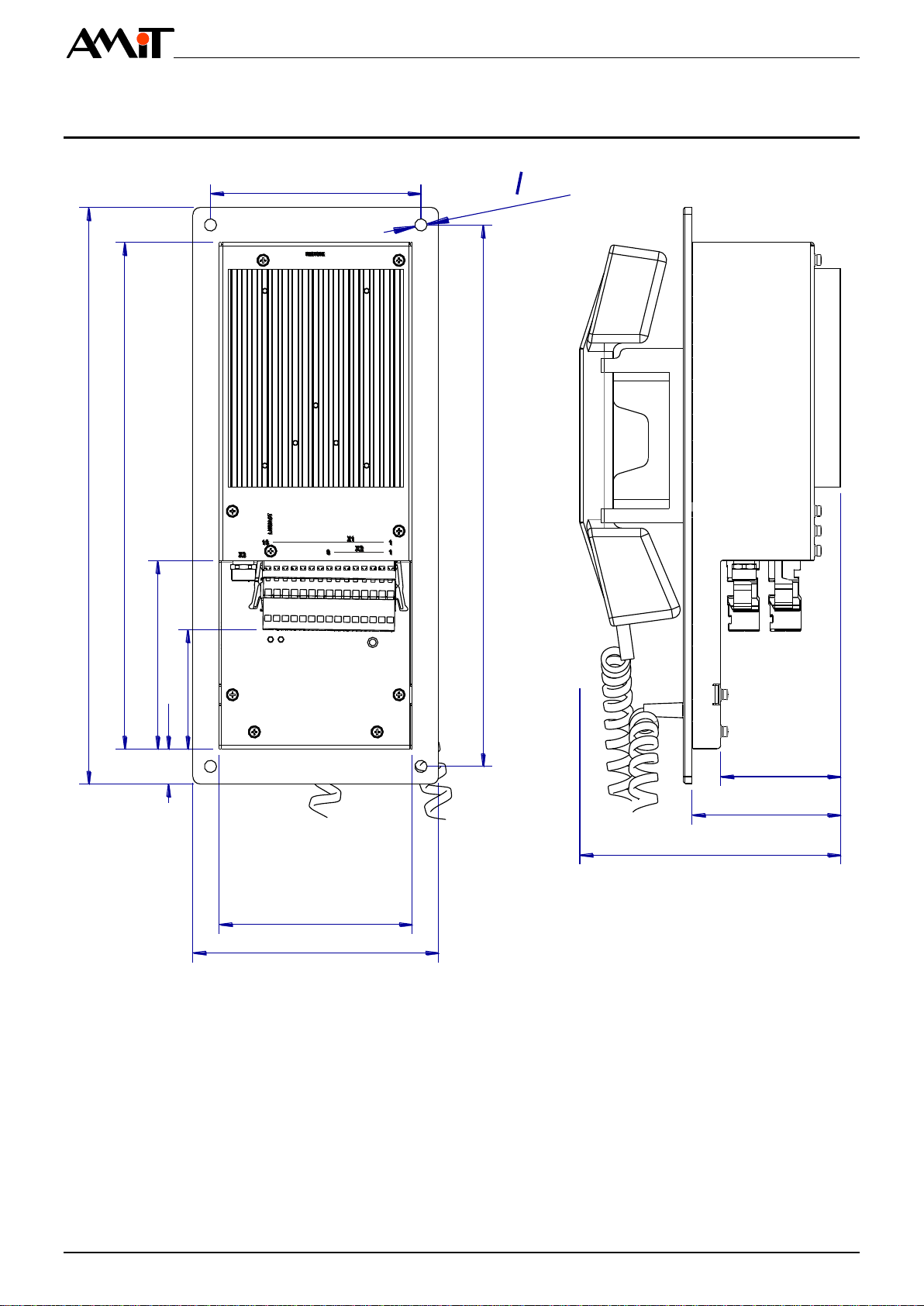
2.1. Dimensions...................................................................................................10
2.2. Design of front panel ....................................................................................11
2.3. Recommended drawing symbol ...................................................................12
3. Product marking ................................................................................13
4. Conformity assessment ....................................................................15
4.1. Other tests....................................................................................................16
5. Power supply......................................................................................17
6. Ethernet...............................................................................................18
6.1. Ethernet line state indication ........................................................................19
7. UIC interface.......................................................................................20
7.1. UIC line state indication................................................................................20
7.2. UIC interface functions.................................................................................21
7.2.1 UIC interface hardware functions .................................................................23
8. Inputs/outputs....................................................................................24
8.1. Digital input...................................................................................................24
8.2. Audio input ...................................................................................................24
8.2.1 Front audio input...........................................................................................24
8.2.2 Rear audio input...........................................................................................25
8.3. Power audio outputs.....................................................................................25
8.3.1 Rules for connecting loudspeakers...............................................................26
8.3.2 Wiring examples...........................................................................................26
8.4. Relay............................................................................................................29
9. Indications and settings....................................................................30
9.1. System LEDs................................................................................................30
9.2. Factory setting..............................................................................................31
10. Phone handset ...................................................................................32
11. Mounting and installation rules........................................................33
11.1. Mounting apertures.......................................................................................34
11.2. Installation rules............................................................................................35
12. Ordering information and completion .............................................36
12.1. Ordering Information.....................................................................................36
12.2. Completion ...................................................................................................36
12.3. Connectors...................................................................................................36
13.Packing ...............................................................................................37
14. Storing.................................................................................................38

RRAM-MCT/E12-XX
rram-mcte12-xx_g_en_100 4/40
15. Maintenance .......................................................................................39
16. Waste disposal...................................................................................40

RRAM-MCT/E12-XX
5/40 rram-mcte12-xx_g_en_100
History of revisions
Document name: rram-mcte12-xx_g_en_100.pdf
Revision
Date
Author of change
Changes
100
22.06.2016
Ondřej Moravec
New document
Related documentation
1. UIC 558 standard
2. UIC 568 standard
Used symbols
Check documentation mentioned above
Important note
Electronic equipment is intended for recycling at the collection point

RRAM-MCT/E12-XX
rram-mcte12-xx_g_en_100 6/40
1. Introduction
RRAM-MCT/E12-xx is a train audio exchange unit with UIC interface, audio
input, built-in power audio amplifier, one Ethernet interface, digital input, and
relay outputs. Hereinafter it will be referred to as exchange unit.
1 × UIC interface
2 × shared audio input
1 × Ethernet 100 Mbps interface
2 × power audio output
1 × digital input 24 V DC
2 × relay output 24 V DC
Power supply voltage 24 V DC
Mounting into panel
Handset with magnetic holder
8 × illuminated control button
Foil with texts
Button LED indication
Functionality according to UIC 568
Rolling stock electronic device
Design according to EN 50155:2007
Basic features

RRAM-MCT/E12-XX
7/40 rram-mcte12-xx_g_en_100
2. Technical parameters
Number of outputs
2 ×
Number of channels
2 ×
Permanent output sinus power
(THD=1 %) 1)
2 × 30 W
Peak music power output
2 × 48 W
Minimum load impedance
6 Ω / channel
Connection point
WAGO 769-675/003-000
Cable counterpart
WAGO 769-115/021-000
Wire cross section
0.5 mm2to 4 mm2
1) At 4 Ω load impedance, with power supply voltage VIN = 24 V DC and
ambient temperature +25 °C.
Quantity 2)
1 ×
Input range
0.707 Veff
Input impedance
20 kΩ
Connection point
Jack 3.5 mm stereo socket
Quantity 2)
1 ×
Input range
0.707 Veff
Input impedance
8.5 kΩ
Connection point 3)
WAGO 769-675/003-000
Cable counterpart
WAGO 769-115/021-000
Wire cross section
0.5 mm2to 4 mm2
Quantity
1 ×
Maximum input voltage
30 V
Maximum input level for Log. 0
7.0 V
Minimal input level for Log. 1
9.2 V
Galvanic isolation 4)
Yes, 1000 V AC / 1 minute
Connection point 3)
WAGO 769-675/003-000
Cable counterpart
WAGO 769-115/021-000
Wire cross section
0.5 mm2to 4 mm2
2) Front and rear audio input share one codec input channel.
3) Rear audio input and digital input share one connector outlet.
4) Galvanic isolation must not be used for dangerous voltage isolation.
Quantity
2 ×
Relay type
Switching, SPDT
Isolation strength
5000 V AC
Nominal switched voltage
250 V AC / 24 V DC
Maximum switched current
8 A
Switch-on time
10 ms
Switch-off time
5 ms
Contact lifetime
20 ×106 cycles
Outputs protection
External circuit-breaker
Connection point
WAGO 769-675/003-000
Cable counterpart
WAGO 769-115/021-000
Audio output
Note
Front audio
input
Rear audio
input
Digital input
Note
Relay outputs

RRAM-MCT/E12-XX
rram-mcte12-xx_g_en_100 8/40
Wire cross section
0.5 mm2to 4 mm2
Number of UIC interfaces
1 ×
UIC functionality
According to UIC 568
Galvanic isolation
No
Connection point
WAGO 769-668/003-000
Cable counterpart
WAGO 769-108/021-000
Wire cross section
0.5 mm2to 4 mm2
Max. number of devices on bus.
20
Cable maximum length
100 cm
Handset fixation
Magnetic holder
Handset detection
Magnetic contact
Button
1 ×
Number of button presses
106
Number of lines
1 ×
Data transmission rate
100 Mbps
Galvanic isolation
Yes
Isolation strength 4)
1000 V AC / 1 min
Connection point
M12 connector, socket, 4 pins D code
Recommended cabling
Min. STP CAT5
Maximum segment length
100 m
Nominal power supply voltage
24 V DC
Power supply voltage range
16.8 V to 30 V DC
Power consumption
Max. 6.2 A at 24 V DC
Inrush current
310 A / < 200 µs
Galvanic isolation
No
Connection point
WAGO 769-675/003-000
Cable counterpart
WAGO 769-115/021-000
Wire cross section
0.5 mm2to 4 mm2
Under-foil button
8 ×
Backlight
Yes, adjustable intensity
Number of operations
106
Acoustic indication
1 × Internal speaker
Mechanical design
To be built into panel
Surface finish cover, panel
Powder coating
Colour cover
RAL 9005
panel
RAL 9005
foil
RAL 7016
foil print
RAL 9010
Mounting
4 × hole 7 mm
Ingress protection rate –
front panel
back cover
IP40
IP20
Weight –netto
–brutto
2.46 kg ±5 %
2.94 kg ±5 %
Dimensions (w × h × d)
(140 × 330 × 149) mm
Package dimensions (w × h × d)
(160 × 360 × 170) mm
UIC interface
Phone
handset
Ethernet
Power supply
Controls
Mechanics

RRAM-MCT/E12-XX
9/40 rram-mcte12-xx_g_en_100
Unit overall mass of plastics
Max 463 g
Included mass of self-extinguishing
plastics
Max 463 g
Exchange unit does not contain
PUR, PVC, Asbestos
Exchange meets
2011/65/EU (ROHS)
1907/2006EU (REACH)
Under-foil buttons
106touches
Operating temperature range
-40 °C to 70 °C
Storage temperature range
-40 °C to 70 °C
Maximum ambient humidity
< 95 % non-condensing
Reliability (MTBF) min.
300 000 h, with 45 °C of ambient
temperature
Expected lifetime
15 years
Exchange unit is supplied with loader, which enables software uploading via Ethernet
line by service application provided for free.
Exchange unit is intended to operate up to 1 400 m above the sea level.
Exchange unit is designed to meet the Temperature Class TX.
According to EN 61373 standard, exchange unit is classified in terms of vibrations
into Category 1, Class B (mounting to vehicle body).
Permissible supplying voltage drop-out duration: max 10 ms (Class S2 according to
Chapter 3.1.1.2 of EN 50155:2007 standard).
For supply voltage switching are permissible conditions of C1 and C2 Class.
The device is not classified according to EN 50128:2011 Railway applications –
Communications, signalling and processing systems –Software for railway control
and protection systems.
The device is not classified according to EN 50129:2003 Railway applications –
Communication, signalling and processing systems –Safety related electronic
systems for signalling.
Dangerous
materials
Components
with reduced
lifetime
Temperatures
Others
Software
equipment
Claims of EN
50155:2007
Safety
classification

RRAM-MCT/E12-XX
rram-mcte12-xx_g_en_100 10/40
2.1. Dimensions
149
85
68
330
290
108
68
20
140
110
310
120
4× o 7
Fig. 1 - RRAM-MCT/E12-xx mechanical dimensions

RRAM-MCT/E12-XX
11/40 rram-mcte12-xx_g_en_100
2.2. Design of front panel
1
2
3
4
Fig. 2 - Design of RRAM-MCTE/E12-xx front panel
Number
Description
Colour
1
Panel
RAL 9005
2
Foil
RAL 9005
3
Foil print
RAL 9010
4
Illuminated elements of foil print
RAL 9010
Legend

RRAM-MCT/E12-XX
rram-mcte12-xx_g_en_100 12/40
2.3. Recommended drawing symbol
Following drawing symbol is recommended for RRAM-MCT/E12-xx.
RRAM-MCT/E12-xx
X3
ETH
M12
UIC7
UIC6
UIC5
UIC4
5
6
7
3
4
8 UIC8
X2
UIC3
UIC2
UIC11
2
GND
PE1
2
SPKA+
SPKA-
SPKB-
SPKB+
Vcc
5
6
7
3
4
9
8
NC1
NO1
C1
10
11 C2
NO2
12
13 NC2
X1
A/DGND
14
15 AIN/DIN
X4
LINE IN
Jack 3,5 mm
Fig. 3 - Recommended drawing symbol for RRAM-MCT/E12-xx

RRAM-MCT/E12-XX
13/40 rram-mcte12-xx_g_en_100
3. Product marking
Type label is located on the side of unit‘s mechanics. Included data are
summarized in the table:
Description
Data
Note
–
Logo AMiT
Producer logo
–
QR code
Product QR code
TYPE
RRAM-MCT/E12-xx
Product type designation
S/N
xxxxxxx
Serial number
MAC
00-09-54-0C-xx-xx
MAC address
FW
APP x.xx / LDR x.xx.x
Version of FW from production
POWER
24 V DC / 5.5 A
Power supply voltage
WEIGHT
2.56 kg
Weight netto
TEST
OK-xx
Routine testing result
HiPot
HiPot-OK
HiPot test result
DATE
dd.mm.yyyy
Production date in day/month/year
format
–
Logo CE
Unit was assessed and complies with
EU legislative requirements
–
Crossed out dustbin logo with
a full stripe
The disposal of electronic equipment is
subject to the regulations on handling
electrical waste.
TYPE
S/N
MAC
FW
POWER
WEIGHT
TEST
HiPot
DATE
RRAM-MCT/E12
AA00000
00-09-54-0C-FF-FF
APP 0.15 / LDR 1.10.0
24 V DC / 5.5A
2.56 kg
OK-AM
HiPot-OK
01.04.2015
Fig. 4 - Illustrative example of type label

RRAM-MCT/E12-XX
rram-mcte12-xx_g_en_100 14/40
TYPE
S/N
MAC
FW
POWER
WEIGHT
TEST
HiPot
DATE
RRAM-MCT/E12
AA00000
00-09-54-0C-FF-FF
APP 0.15 / LDR 1.10.0
24 V DC / 5.5 A
2.56 kg
OK-AM
HiPot-OK
01.04.2015
Fig. 5 - Location of type label (illustrative picture)

RRAM-MCT/E12-XX
15/40 rram-mcte12-xx_g_en_100
4. Conformity assessment
Providing, that device is correctly used, it complies the requirements of Czech
governmental decree NV616/2006. The compliance assessment with
NV616/2006 has been performed in accordance with harmonized standard
EN 50121-3-2:2006.
Tested in accordance
with standard
Type of test
Classificati
on
EN 55011:2009
Industrial, scientific and medical
equipment –Radio-frequency
disturbance characteristics –Limits and
methods of measurement
Complies
EN 61000-4-2:2009
Electromagnetic compatibility (EMC) –
Part 4-2: EMC –Testing and
measurement techniques –Indirect
electrostatic discharge immunity test,
contact discharge
±8 kV
EN 61000-4-2:2009
Electromagnetic compatibility (EMC) –
Part 4-2: EMC –Testing and
measurement techniques –Indirect
electrostatic discharge immunity test,
aerial discharge
16 kV
EN 61000-4-3:2006
Electromagnetic compatibility (EMC) –
Part 4-3: Testing and measurement
techniques –Radiated, radio-frequency,
electromagnetic field immunity test,
800 MHz to 1000 MHz
20 V/m
EN 61000-4-3:2006
Electromagnetic compatibility (EMC) –
Part 4-3: Testing and measurement
techniques –Radiated, radio-frequency,
electromagnetic field immunity test,
1000 MHz to 2100 MHz
10 V/m
EN 61000-4-3:2006
Electromagnetic compatibility (EMC) –
Part 4-3: Testing and measurement
techniques –Radiated, radio-frequency,
electromagnetic field immunity test,
2100 MHz to 2500 MHz
5 V/m
EN 61000-4-4:2012
Electromagnetic compatibility (EMC) –
Part 4-4: Testing and measurement
techniques –Electrical fast transient/burst
immunity test, power supply
4 kV
EN 61000-4-4:2012
Electromagnetic compatibility (EMC) –
Part 4-4: Testing and measurement
techniques - Electrical fast transient/burst
immunity test, inputs / outputs
2 kV
EN 61000-4-5:2006
Electromagnetic compatibility (EMC) –
Part 4-5: Testing and measurement
techniques –Surge immunity test
4 kV
EN 61000-4-6:2009
Electromagnetic compatibility (EMC) –
Part 4-6: Testing and measurement
techniques –Immunity to conducted
disturbances, induced by radio-frequency
fields
10 V

RRAM-MCT/E12-XX
rram-mcte12-xx_g_en_100 16/40
4.1. Other tests
Exchange unit has been assessed and approved for use in railway applications
according to standards:
Tested in accordance
with standard
Type of test
Result
EN 50155:2007
Railway applications –Electronic
equipment used on rolling stock
Complies
EN 50121-3-2:2006
Railway applications –
Electromagnetic compatibility –Part 3-
2: Rolling stock –Apparatus
Complies
EN 61373:2010
Railway applications –Rolling stock
equipment –Shock and vibration tests
Category 1,
Class B
EN 61000-4-29:2000
Electromagnetic compatibility (EMC) –
Part 4-29: Testing and measurement
techniques –Voltage dips, short
interruptions and voltage variations on
d.c. input power port immunity tests
S2, C1, C2
EN 60068-2-1:2007
Environmental testing –Part 2-1:
Tests –Test A: Cold
Complies
EN 60068-2-2:2007
Environmental testing - Part 2-2: Tests
–Test B: Dry heat
Complies
EN 45545-2:2013
Railway applications –Fire protection
on railway vehicles –Part 2:
Requirements for fire behaviour of
materials and components
HL3
UIC 558 ed. 1
Remote control and data cable –
Standard technical features for the
equipping of RIC coaches
Complies
UIC 568 ed. 3
Loudspeaker and telephone systems
in RIC coaches Standard technical
characteristics
Complies

RRAM-MCT/E12-XX
17/40 rram-mcte12-xx_g_en_100
5. Power supply
The RRAM-MCT/E12-xx unit can be powered only by DC power supply +24 V.
The power supply conductor’s cross-section must be at least 0.75 mm2.
X1
1
Fig. 6 - X1 connector location, designation of pin n. 1
The PE terminal is internally connected with exchange unit cover and panel as
well as with metal caps of all connectors.
Connector type WAGO 769-675/003-000
Connector
Pin
Signal
Description
X1
1
PE
Chassis, ground
2
GND
Power supply, ground
3
Vcc
Power supply input, +24 V DC
4
SPKB+
Output of channel B +
5
SPKB-
Output of channel B –
6
SPKA-
Output of channel A –
7
SPKA+
Output of channel A +
8
C1
Relay 1, common pole
9
NO1
Relay 1, switching pole, normal open
10
NC1
Relay 1, switching pole, normal connect
11
C2
Relay 2, common pole
12
NO2
Relay 2, switching pole, normal open
13
NC2
Relay 2, switching pole, normal connect
14
A/DGND
Ground for analogue-digital input
15
AIN/DIN
Analogue-digital input
Power supply voltage is connected to power supply terminals Vcc and GND of
X1 connector. PE terminal is used for connection of chassis.
When installing, it is recommended to connect the PE terminal in single point of
switchboard with chassis of equipment where the exchange unit is installed.
Connecting to
PE
Connector
wiring

RRAM-MCT/E12-XX
rram-mcte12-xx_g_en_100 18/40
6. Ethernet
Ethernet interface allows communication with 100 Mbps speed. Connector is
located on the rear side of the unit’s cover.
X3
1
Fig. 7 - Ethernet connector location, designation of pin n. 1
M12 connector type, socket 4 pins, D coding
Connector
Pin
Signal
Description
X3
1
Tx+
Data transmission positive signal
2
Rx+
Data reception positive signal
3
Tx-
Data transmission negative signal
4
Rx-
Data reception negative signal
5
SHLD
Cable shielding
1
4
3
2
4
1
3
2
5
Fig. 8 - Wiring of M12 Ethernet connector, front view
Connectors
wiring

RRAM-MCT/E12-XX
19/40 rram-mcte12-xx_g_en_100
6.1. Ethernet line state indication
Ethernet line status is indicated by one LED located on the unit cover rear side,
under connectors. Following table describes meaning of the individual LEDs:
LED
Colour
LNK/ACT
Green
LED
Status
Description
LNK/ACT
ON
Exchange unit connection to Ethernet network
Flashing
Data frame receiving or transmitting
LINK/ACT
Fig. 9 - Ethernet LED indication

RRAM-MCT/E12-XX
rram-mcte12-xx_g_en_100 20/40
7. UIC interface
Unit is equipped with UIC interface according to UIC 558 and UIC 568
standards.
X2
1
Fig. 10 - Location of connector X2 with UIC interface, designation of pin n. 1
Connector type WAGO 769-668/003-000
Connector
Pin
Signal
Description
X2
1
UIC1
Audio signal of announcement +
2
UIC2
Audio signal of announcement –
3
UIC3
Phone line +
4
UIC4
Phone line –
5
UIC5
Indication of program announcement +
6
UIC6
Indication of program announcement –
7
UIC7
Indication of priority announcement +
8
UIC8
Indication of priority announcement –
7.1. UIC line state indication
State of UIC line is indicated by three LEDs on front panel. Following table
describes meaning of individual LEDs.
LED
Colour
Description when on
AOC
Yellow
Priority announcement in progress
TOC
Yellow
Phone call in progress
POC
Yellow
Program announcement in progress
AOC
TOC
POC
Fig. 11 - UIC line state indication
Connector
wiring
Table of contents
Popular Industrial Equipment manuals by other brands

schmalenberger
schmalenberger FLUVO xanas 1,5 Operator's manual

FMS
FMS FMS-cradleGUARD Operating Manual and Installation Instructions

ABB
ABB RELION Series Product guide

Elecro Engineering
Elecro Engineering G2 Installation & operating manual

BVA Hydraulics
BVA Hydraulics CB1438 instruction manual

IMET
IMET VTF 500 INSTRUCTION MANUAL, MAINTENANCE AND SPARE PARTS