TROUBLESHOOTING
86073955-R3
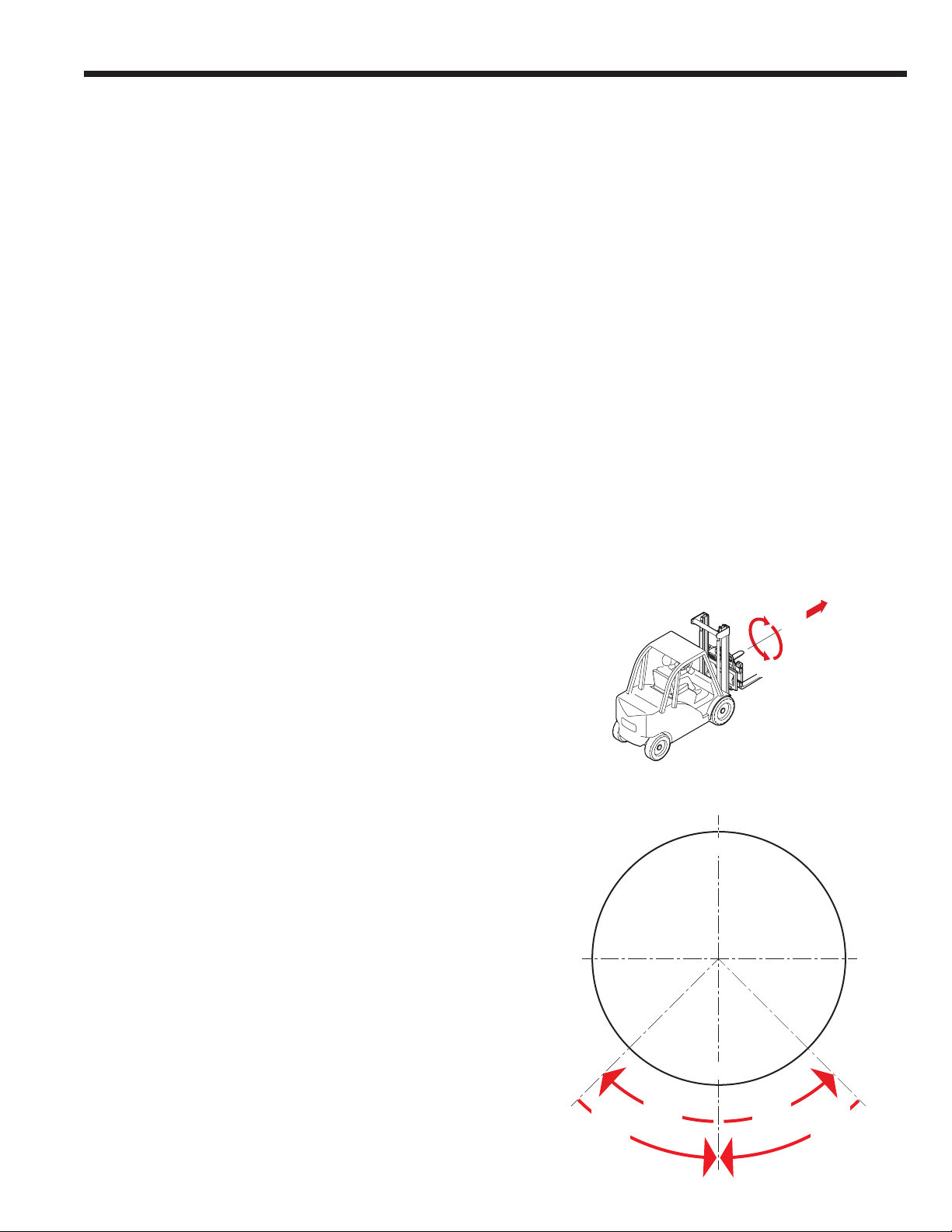
3.3-3 Rotation With Load
1 Attachments with Single Drive –Rotate a load
requiring approximately 3/4 of attachment maximum
torque capacity. Note gauge readings during rotation:
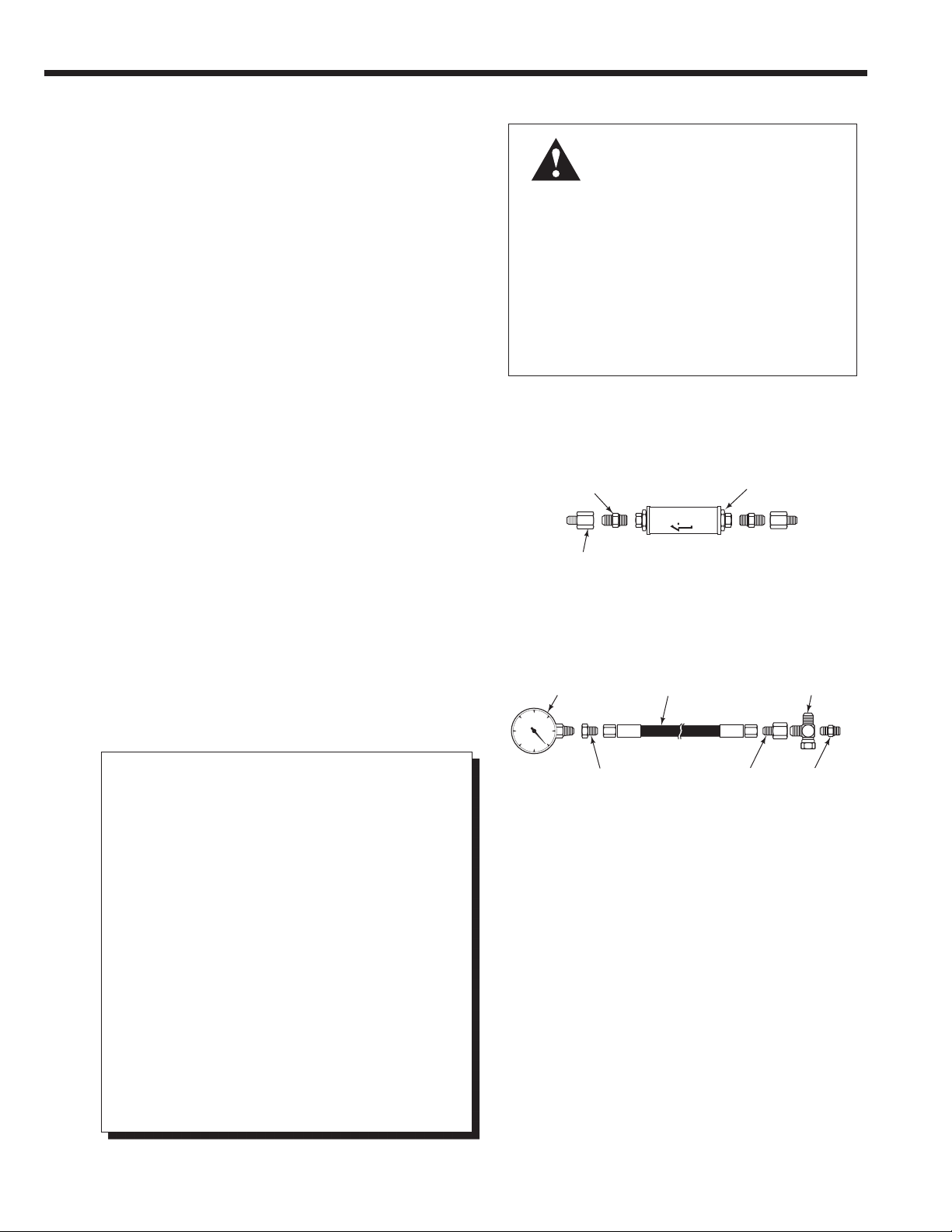
• If the higher gauge reading is substantially less than
the truck pressure as measured at the carriage hose
terminal, the rotator motor gerotor/geroler set may
need repair. Refer to Section 4.3.
• If the higher gauge reading is close to truck pressure
as measured at the carriage hose terminal and no
rotation occurs, the rotator motor output shaft or drive
box may need repair. Continue troubleshooting.
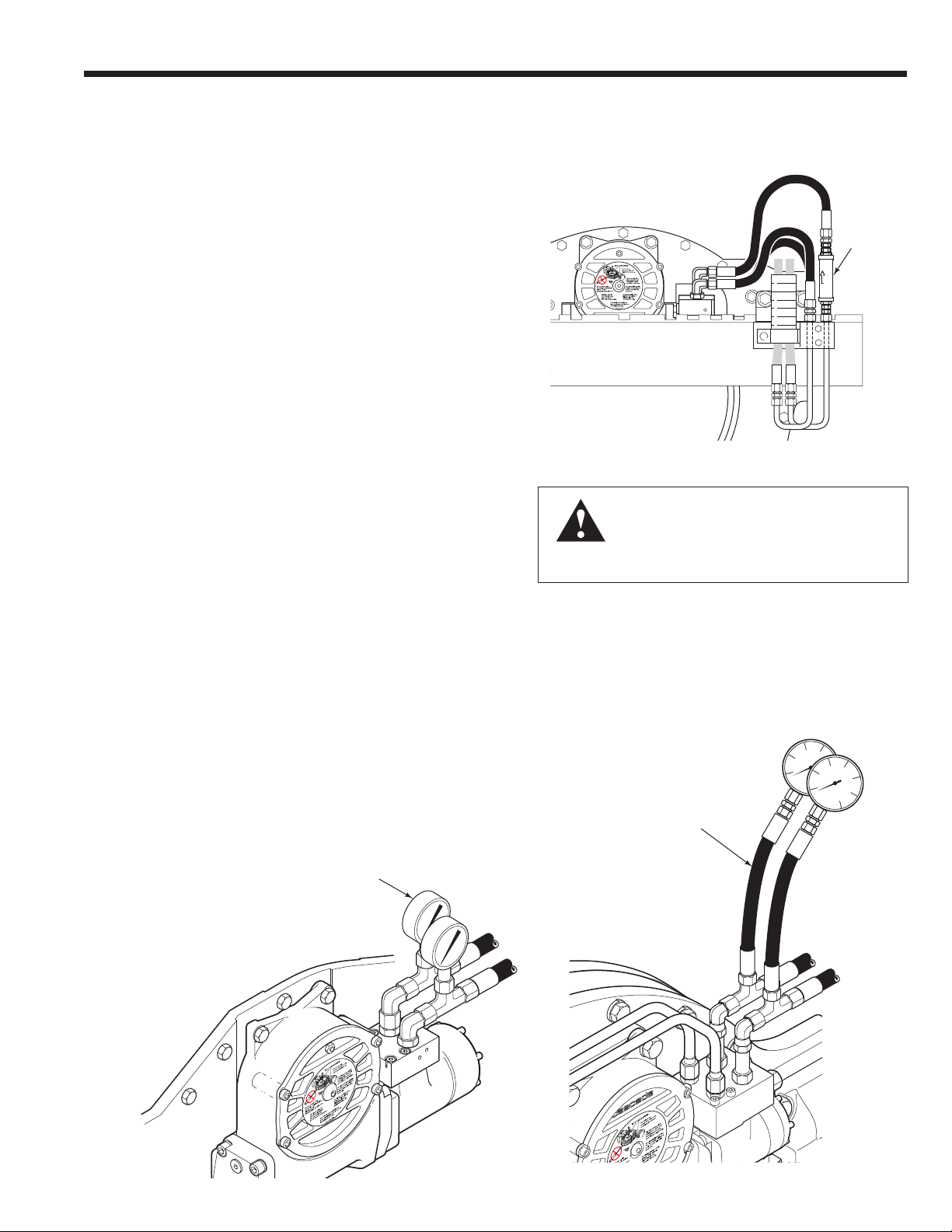
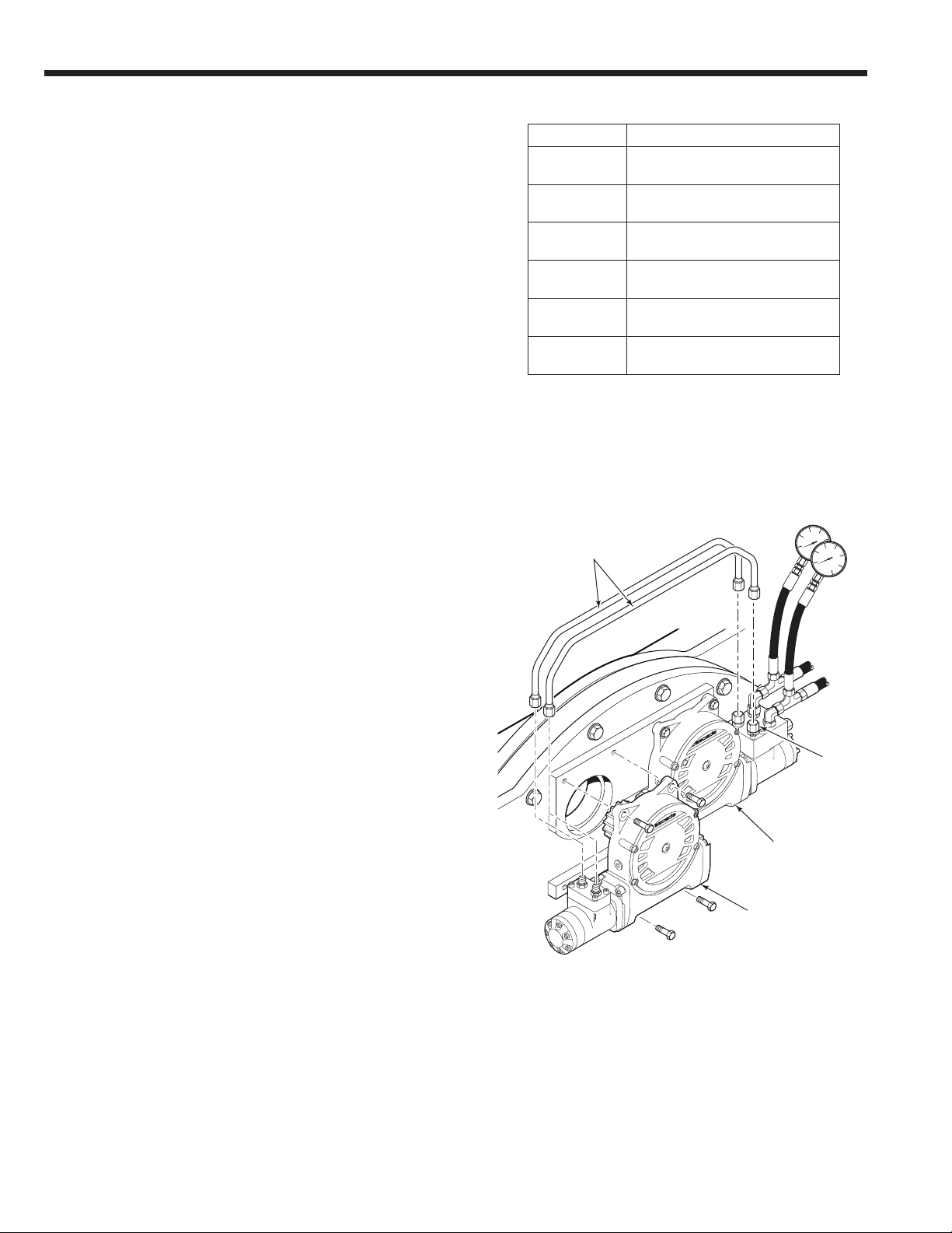
Attachments with Dual Drive – Remove the left drive
group from the attachments as described in Section
4.2-1. Cap the connector fittings on the right hand drive
group. Rotate a load requiring approximately 1/3 of
attachment maximum torque. Note gauge readings
during rotation:
• If the higher gauge reading is substantially less than
truck pressure measured at the junction block/hose
terminal, the RH motor may need repair.
• If the higher gauge reading is close to truck pressure
measured at the junction block/hose terminal, and
no rotation occurs, the RH motor output shaft or drive
may need repair. Continue troubleshooting.
• If the higher gauge is close to truck pressure,
measured at the junction block/hose terminal, and
rotation occurs, the LH motor output shaft or drive
may need repair. Continue troubleshooting.
2 Remove the motor from the drive box assembly as
described in Section 4.3-1.
3 Reinstall the hoses to the rotator fittings. Actuate the
ROTATE circuit.
• If the rotator motor shows rotational output, the drive
box may require service. See Section 4.2.
• If the rotator motor shows little or no rotational output,
the rotator motor requires service. See Section 4.3.
Disconnect the
crossover tubes
Cap fittings
Right hand
drive group
Left hand
drive group
Model Maximum Torque Capacity
45G, 55G 63,000 in.–lbs. @ 2300 psi
(7,118 Nm @ 160 bar)
65G 80,000 in.–lbs. @ 2300 psi
(9,039 Nm @ 160 bar)
80G 73,000 in.–lbs. @ 2,300 psi
(8,248 Nm @ 160 bar)
100G 98,000 in.–lbs. @ 2,300 psi
(11,037 Nm @ 160 bar)
130G ★128,000 in.–lbs. @ 2,300 psi
(14,462 Nm @ 160 bar)
160G ■145,000 in.–lbs. @ 2,300 psi
(16,383 Nm @ 160 bar)
★Rated at 15 GPM (56L/min.) flow.
■Rated at 20 GPM (75L/min.) flow.