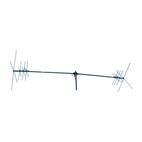
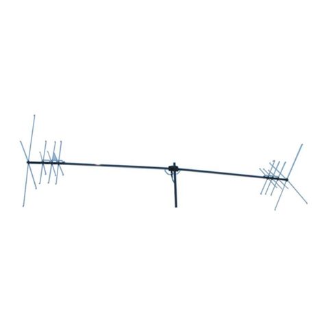
MFJ MFJ-1768 User manual

144/440 MHz Dual Band Yagi
Model MFJ-1768
INSTRUCTION MANDAL
READ ALL INSTRUCTIONS BEFORE OPERATING EQUIPMENT
MFJ ENTERPRISES, INC.
P.O. BOX 494, MISSISSIPPI STATE, MS 39762, USA

Red Cap
MEI-1768
Dual Band Yagi
36 3/8" (A)
11
3/8" (D)
Red
Block
11
Red
3/8" (D)
Boom
11
1/2" (E)
Yellow
1 1
Block
7/8"
(F)
37" (B)
White
11
White
5/8" (G)
6 3/8" x 1/4"
Tube
_
13 3/4" (H)
19 1/4"x 1/4"
/-1
Tube
L-Bracket
with Coax Connector
Green
Capacitor
Thin Plates
Ferrite Balun Beads
Green
U-Bolt and
Saddle Clamp
Red Cap
1/4 - 20 Nuts
and Split Wahers
NOTE:
This drawing is not to scale

U-Bolt and
Sacicle Clamp
MFJ-1768
Dual Band Yogi
Red Cap
11
3/8" (D)
36
3/8" (A)
_--
11
3/8" (D)
Boom
11
1 /2" (E)
11
7/8" (F)
3T (B)
11
5/8" (G)
Red
Red
Yellow
Block
White
} Block
White
1
6 3/8" x 1/4"
Tube
13 3/4" (H)
19 1/4" x 1/4
Tube
Green
Capacitor
Thin Plates
L-Bracket
with Coax Connector
Ferrite Balun Beads
39 3/4" (C)
Green
1/4 - 20 Nuts
and Split Wahers
NOTE:
This drawing is not to scale

MEI-1768 Dual Band Yagi
Instruction Manual
MFJ-1768
Instruction Manuil
Table of Contents
Introduction
2
Choosing a Location for the Antenna
2
Tools and Time Requiretnents
3
MFj-1768 Parts List
3
Safety Precautions
Assembly and Installation
4
Timing
7
Grounding Considerations
7
Maintenance
8
Technical Assistance
8
1

ME1-1768 Duval Band Yagi
hist
-
niet
-
ion Manna'
MFJ-1768
Instruction Manual
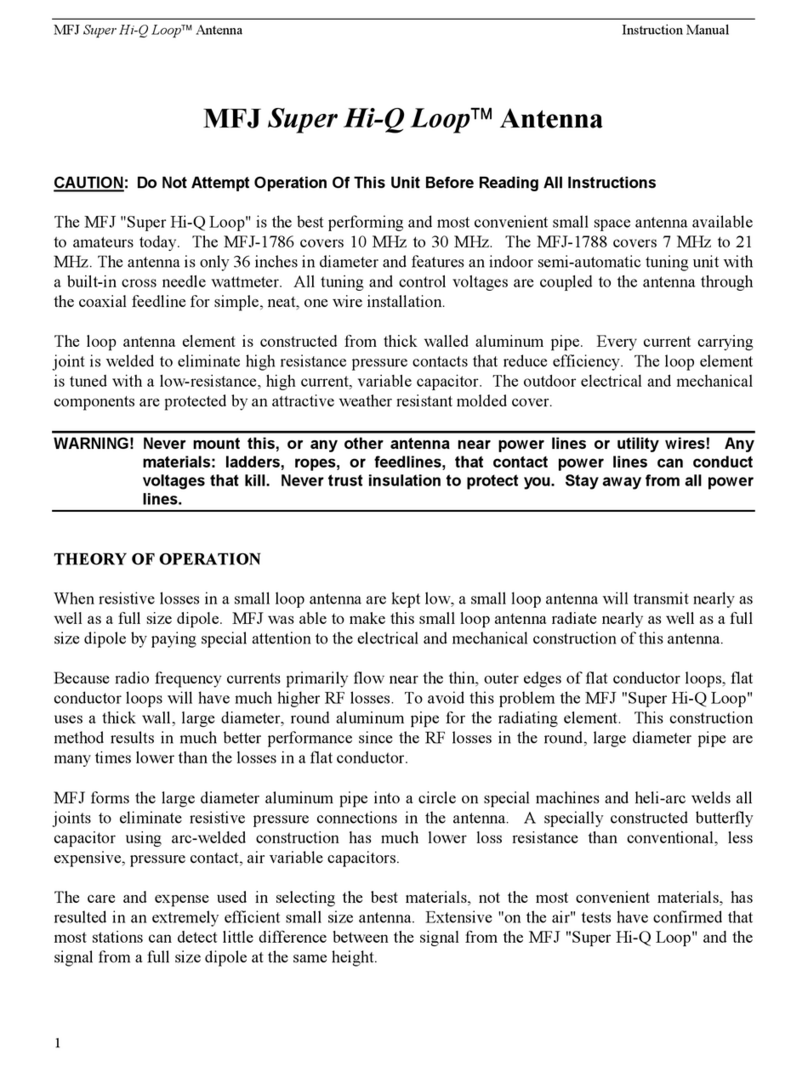
1NTRODECTION
The MO-1768 is a National Bureau of Standards (NBS) style yagi that provides optimum gain and
front to back ratio on both the 2 meter and the 70 centimeter bands. On the 2 meter band the MFJ-1768
is a 4 element antenna, on the 70 centimeter band the MR1-1768 is a 7 element antenna. It is constructed
using lightweight and strong 6061-T6 aluminum material for both the elements and the boom. The MFJ
1768 elements are insulated from the boom to eliminate the problem of poor electrical contact to the
boom. This antenna uses a dual balante driven element that provides a clean pattern with minimal
skewing. The antenna's 1/4" diameter driven elements provide wille bandwidth that covers both bands
with a low SWR. This antenna uses a single feedline with a ferrite decoupled current balup for both
hands. This technique eliminates the need for extra coax tables, and stops all the parallel RF current. on
the coax shield. This prevents unwanted radiation.
The MH-1768 is an excellent antenna for use with dual band transceivers. Since the MD-1768 is a dual
band antenna there is no need to switch antennas when changing bands. With the use of a duplexer
(such as the MD-016) you can connect two different radios (two different bands) to the ML1-1768 at
the same time.
CHOOSING A 1,OCA1 ION FOR THE ANTENNA
The NIFJ-1768can be mounted on any 1" to 1 1/2" mast
(conduclive or non-conduclive)
capable of
supporting the weiglit of the antenna and the torque developed by the boom. The MFT-1768 can he
mounted vertically (generally used for FM transmission), or horizontally (commonly used for SSB
transmission).
The best performance on receiving and transmitting will be obtained by mounting the antenna as high as
possible in a clear location above or away from buildings, feed biles, utility wires, and other antennas.
Your ingenttity and particular circumstances will determine the final mounting method.
The MD-1768 is a directional antenna with a major high gain forward lobe and fewer lover gain side
and back lobes. The operating frequency of this antenna is used only in line of site communication. For
that reason it is best to molmt the MD-1768 on a rotor and be able to orient its major lobe toward the
desired location and obtain maximum performance. Also since the side and the back lobe exist but with
low gain, it is possible to use these lobcs for local area communication without rotating the antenna

N1FJ-1768 I)ual Band Vagi
Instruction Mantra!
TOOLS AND TIME REQUIREMENTS
The estimated time of assembly for this antenna (including reading time) is 1 hour.
Tools required for this antenna are as follows:
-
#1 Phillips screwdriver
-
1/4" nut driver
-
7/16" open end wrench
-
Push nut assembly tool (supplied)
Eye protection
-
Temporary mast and a table, or flat ground
MFJ
-
1768 PARTS LIST
The MH-1768 parts and hardware are stainless steel, aluminum, or non-corrosive material.
As you unpack your antenna you should Eind the following list:
[ ] One bundle of long elements for the two meter band
[ J One bundle of short elements for the 440 Mhz band
()ne bag containing the following, hardware:
-
Twenty 3/16" ID insulators
-
30 push nuts 3/16" ID
-
Two 1 1/8" red end caps
-
One U-bolt and saddle damp assembly
-
Push nut assembly tool
-
-
Vwo capacitor thin plates for 2 m elements
-
Two 4-40 x 1/2" SST screws
-
Ten 4-40 SST nuts
One 1 1/8" diameter (6061-T6) aluminum tubing boom
SAFETY PRECAUTIONS
.
WARN NG
This antenna is an electrical conductor.
(.:ontact with power lines can .result in de th, ot serious injuries.
-
Do
:not
this antenna- witere there is any possibilitv OI contact witli power rables Or.
serNiee drop to buildings.
The: antenná stippOrting mast andlor tower should not be
-
elose to any power lines
-
during
installation Or
re
tiloval in theevent the system stronk! accident:Lily rail.
- Fellow the guidelines for antenna in.stallation recommerided hy the
consumer
product safety
.
commission.
3

MEI-1768
Dual Band Yagi
Instruction Manual
hee f;:this: antenna out; o f ~cach of ~ dults, ~ildi en, and a
itm~ls cnv: co tact iti~i h this ;;
'
... .
goiiithe•
a
otie.1)0:.:•••:s.,4ifiiy:
•
:•••
••••••••
:
-..:N.é.vé'.ópiertte11 is
n rt t
•
en tt
•
n e:tr• R seusit t
v
.
n
•
e
.
(1Cal
.•
C
.
VM 7.
•
tS
.
.Sle
.
l'As.pac
.
e
tint‘ers..
Keel) the feedline
of th is
a.ntettptt...tway.:.trolit
'Be
.... . :.•
•••••••••;•:•....:••:
••
• •••
•••:. .. . ... :.•
:••:..•
•
.
u
til
it
•
.•••••:..
••
•• ••
.. • ...
:.:•••••
.. • ••-...
••.::••
. bc
a
.. : . • ..e
n
oug
h
. : ..
.
.
.
.
.....
.. .......
•• • :•••:
••
• -:"
•
• •
-• :
-•"• ".
. .
.eiti
. . ••:..-
•••:..
•••:•••• •• • • •
..•:: • :
• ". •• •
"•••• •••••
.• •
•
....
.
.
•
•
•-• •
.
..
.:•
•
• •
• •
sertous
-•••
s
rt
r
e
,tiie
:
:.•
•
.• ••...:•
:
t
....
. .
•
• ..
"
•:•:.
.. . .
••
•••••"
.
. . .
.
•
•••:::•:•••.• v
olli
::v
•
ctittseottAti•
.
ASSEMBLY AND 1NSTALLATION
During assembly of this antenna refer to figures in this manual and the picture on the front cover. The
assembly instructions tell you, step by step, how to install the insulators, the drives and parasitic
elements, and the U-bolt assembly.
All parasitic elements, for 2 meter and 70 cm band, are colon coded at their ends and alphabetically
labeled on ligure-1 and on ligure inside tiont cover to facilitate the antenna assembly_ Pay extreme case
while assembling the antenna and ahvays refer to the mentioned figures.
Step by Step Procedure
1-
Prepare a strong mounting mast that can withstand a wind load of at least 2 square Peet and permit
easy installation. Set up a table or other stable support.
2-
Sort out party you have unpacked info groups of similar Aarts. These consist of
1 1
twenty 3/16" ID black insulators
[]30 push nuts 3/16" ID
[1 One U-bolt assembly
[ 1 Two capacitor thin platen for 2 in elements
Two 4-40 x 1/2" SST serews and ten 4-40 SST nuts
1
-
1
0119 1 1 /8
" diameter (60(>1-
-
V) aluminum tubing boom \ ith matching network and SO-239
connector on an "1," bracket
(pw-ctss
-
embled)
[
One bundle of long elements ffir the two meter band
GROUP
-
Two 19 1/4" x 1/1" long tubes
-
One 3() 3/8"
_Block
-
One 37" long
13
....... _White
-
One 39 3/4" long....
C
.Green
4

MFJ-1768 Dual Band Yagi
Instruction Manaal
[ ] One bundle of short elements for the 440 MHz band (eiglit of them)
GROUP 2
-
Two 6 3/8" x 1/4" short tubes
-
Two 11 3/8" long
D
Red
-
One 11 1/2" long
E
Yellow
-
One 11 7/8" long
F
Black
-
One 11 5/8" long
G
White
-
One 13 3/4" long
H
Green
Group 1
Group 2
J
6-3/8" (2)
1
19-1/4"(2)
F3lock
__
36-3/8'
I
D
i
Red
11-3/8"
A ,---
-,
37''
B '
White ---1
E
■
Yellow--
i
11-1/2"
Cr
39-3/4''
F
I
-
11
-
5/8
"
11-7/8"
Green
1
C-2.----
H
r
Block
---1
Whtle
i 13-3/4"
Green '
3- Insert eighteen of the 3/16" ID black insulators using your thumb into the designated holes on the sides
of the 1-1/8" boom.
F1G URE
11
kek"
.
to ligare on inside front cover and ligure 2 to loeide the designated holes and the installatimij
example
I,ay the antenna boom on a flat stal
-
ace, a table perhaps, with the feed plate faeing up.
5- Refer to Figure 3 and start the assembly of the driven elements as follows:
/1
-
The 2 meter driven element:
Align the holes drillecl on the end of a 19 1/4" x 1/4" tube with the 1-10 screws located on the
rear end of the feed plate (
3for
exacl localion ).
Insert the 4-40 screws into these
holes. Thread 4-40 mits over the two screws and tighten to ensure goud connections. Repeat
the same procedure for the remaining 19 1/4" x 1/4" driven element.
1 1 /8 '
B
-
The 441) :1111.: drive', element:
Align the holes drtiled on the end of a 6 3/8"" x 1/4" tube
with the 4-40 screws located on the front end of the feed
plate
see
fiKure
3 ffir exact location )
Insert the 1-10
screws Mto these !mies
T hread 4-40 nuts over the two
screws and tighten to ensure Bood connections Repeat the
same procedure Hu the lemainimi h 1'8" x 1,i4" driven
element,
tik,C1hr
Ir
tof
IFIGURE 2

63/8" x 1/4
70 Centimeter
Driven
Element
Instruction Nianual
MFJ-1768 Dual Band Yagi
4-40
nut
19 1/4" Y. 1/4"
Tube
Feed Plato
4-401ockinQ riuls
j
19 1/4" x 1/4"
2 Met et
Driven Element
FIGURE
•
11
4
—
4
-
40 scres,w
(.apaciter
11)in plats
6 3/8' x 1/4'
Tube
Refer to figure 4 and figure 5 and start the assemhly of the parasitic elements
6- Assemble one push nut on each of the parasitic elements of both groups (fabeled
A-11)
using the
provided Jool.
Slide the push nut until it reaches the first mark en the element (see figure 4
_
)
WARN ING:
1f 3,ou pasled the mark, do not ny to slide the push nut haekward Sliding the
push nut baekward wilt tend to losrage it
,
instead slide the push nut all tie
way
out
titen
reinstall it. Nole: Extra push nuts are providedfor replacement of damaged ones.
Note : for section 7
and 8 refer to figure 1, figure 4 and figure 5 while assembling
7-
Insert element "A" ( black end ) from GROUP 1 into its
designated hole in the boom, as shows in the ligure en the
inside front cover. Assemble another push nut from the other
side ( see ligure 4 and figure 5 ), and slide it until it reaches the
3/16" black insulator. Make sure that the element is secured
in
place with minimum free play .
8-
Repeat the previous procedure for the remaining elements
from GROUP 1 and GROUP 2. See inside front cover and
figure 1 for 'bil detail en hole positions, elements locations,
colon code, and alphabetical label
.
9-
After installing all the parasitic elements
.
insert
the lj-bolt in
its designated holes keeping in mind the polarization of the
antenna (see figure 6).
Push Nut Push Nut Tool
Do not slide
push nut backwards
FIGURE 4
6

1/4 - 20 Nuts
and
Split Washers
Boom
Mast
Saddle Clamp
1111111111111111111111111.
1111iIII111
1
■
111111!1111
MEI-1768 Dual Band Yagi
list ruct ion Manna!
Insuiator
Push Nut
Element -
FIGURE
61
FIGURE 5 1
10-
Lay the antenna on a flat surface to install the thin capacitor plates for the 2 meter driven elements.
Insert. a 4-40 x 1/2" scrcw through the hole located in the middlc of the element, pass it through a thin
capacitor plate. Thread a 1-10 nut on the screw and tighten. Repeat this procedure for the second
driven element (sec Figure 3).
IMPORTANT: Make sure the capacitor thin piate font] a 90 degrees angle with the 2 meter
driven elements
11-
The antenna is ready now to be mounted on the permanent mast and ready to be used ()n the air.
Note:
Make sure to dress the feed coax eable along the boom and run it along the permanent
mast. llold it. in biace using either electric tape or black cabie ties
TUNING
The ME1-1768 is pre-tuned on both bands, additional tuning is not required. The antenna bandwidth is
verg wide, it covers the entire 2 meter and 70 centimeter band with an SWR less than 2.0:1.0.
GROUNDING (1):11)EIZ.V1 (ONS
Althou2h this antenna is designed to operate efficiently without the requirement of an carth ground,

SAFETY GROENDING MUST STIL!, 13E PROVIDED to proleet equipment, property and persons
from the hazards of lightning strikes and other weather related electrical discharges. In addition the.
coaxial cable feeding the officium should ha\e the shield
esotincled to eliminate the risk of any
Indom
equipment failure trom allowing hatardous voltages 1rolll appearing indoors and creating a shock
hazard.
7

MEI-1768 Dual Band Yagi
Instruction Mam
►
al
Adequate protection can be accomplished by grounding the shield of the coax where it enters the
building to a good earth ground or directly burying the cable in the earth for several feet before it enters
the building_ The coaxial cable should be totally disconnected from the station during threatening
weather conditions for maximum lightning protection.
A less effective method of protecting station equipment is to install an in-line coaxial lightning arrestor
with a heavy duty ground wire to a suitable earth ground, or a safety switching system as part of the
basic ham station equipment.
MAINTENANCE
Your antenna is constn
►
cted of heavy duty non corrosive materials and should withstand normal
climates for many years. The use of some type of coaxial connector moisture protection is
recommended at the bottom coax connection and also around the center-feed connections, especially in
coastal areas where salty mist is commonplace.
GE makes a pure silicone grease called "SILICONE DIELECTRIC COMPOUND" that can be
applied SPARINGLY to the threaded area of the female connector. This compound, or even a clear
silicone heat sink compound, will prevent moisture from entering the connector through the threads and
protect the connectors from corrosion. THIS IS THE SAME TYPE OF SEALER THAT
COMMERCIAL ANTENNA INSTALLERS AND CATV COMPANIES USE WITH GREAT
SUCCESS.
A less desirable, but stil) adequate sealer is the automobile seam sealer commonly sold as "coax seal".
This is a seini-pliable black sealing compound.
When installing any "coax seal", NEVER completely cover the barrel of the coax connector. The sealer
should ONLY be placed near the junction of the threaded part of the chassis connector and the knurled
area of the male connector. This will leave the bottom of the male outer sleeve open and permit the
connector to "breathe" so it does NOT collect moisture!
TECEINICAL ASSISTANCIt
If you have any problem with this unit first check the appropriate section of this manual. 1f the
manual does not reference your problem or your problem is not solved by following the manual you
may call MEJ
.
toll-free at 1-800-647-TECH (8324) or FAX to 601-323-6551, or
. Outside of the continental 14 S.A. 601-323-5869. You
will be best served if you have your unit, manual, and all information on your station handy so you
can answer any questions the technicians may asL
You can also send questions to MF.1 Enterprises, INC., P.O. I3ox 49:1, Mississippi State, MS 39762.
Send a complete description of your problem, an explanation of exactly how you are using your unit
and a complete description of your station
8
Other manuals for MFJ-1768
1
Table of contents
Other MFJ Antenna manuals
Popular Antenna manuals by other brands

TERK Technologies
TERK Technologies TV44 owner's manual

l-com
l-com HyperGain HG2424G Installation instruction

RCA
RCA ANT1268E quick start guide

Taoglas
Taoglas TGX45 Series installation instructions

INAC
INAC AH-521 Instructions for fitting and use

ESCO Technologies
ESCO Technologies ETS Lindgren 3147 user manual