MFJ MFJ-1762 User manual

MFJ-1762 Instruction Manual
Introduction: Thank you for purchasing the MFJ-1762 three-element six-meter Yagi.
The MFJ-1762 is a light-weight directional antenna especially designed for installation
with readily-available TV-type masts, mounts, and hardware. The driven element employs
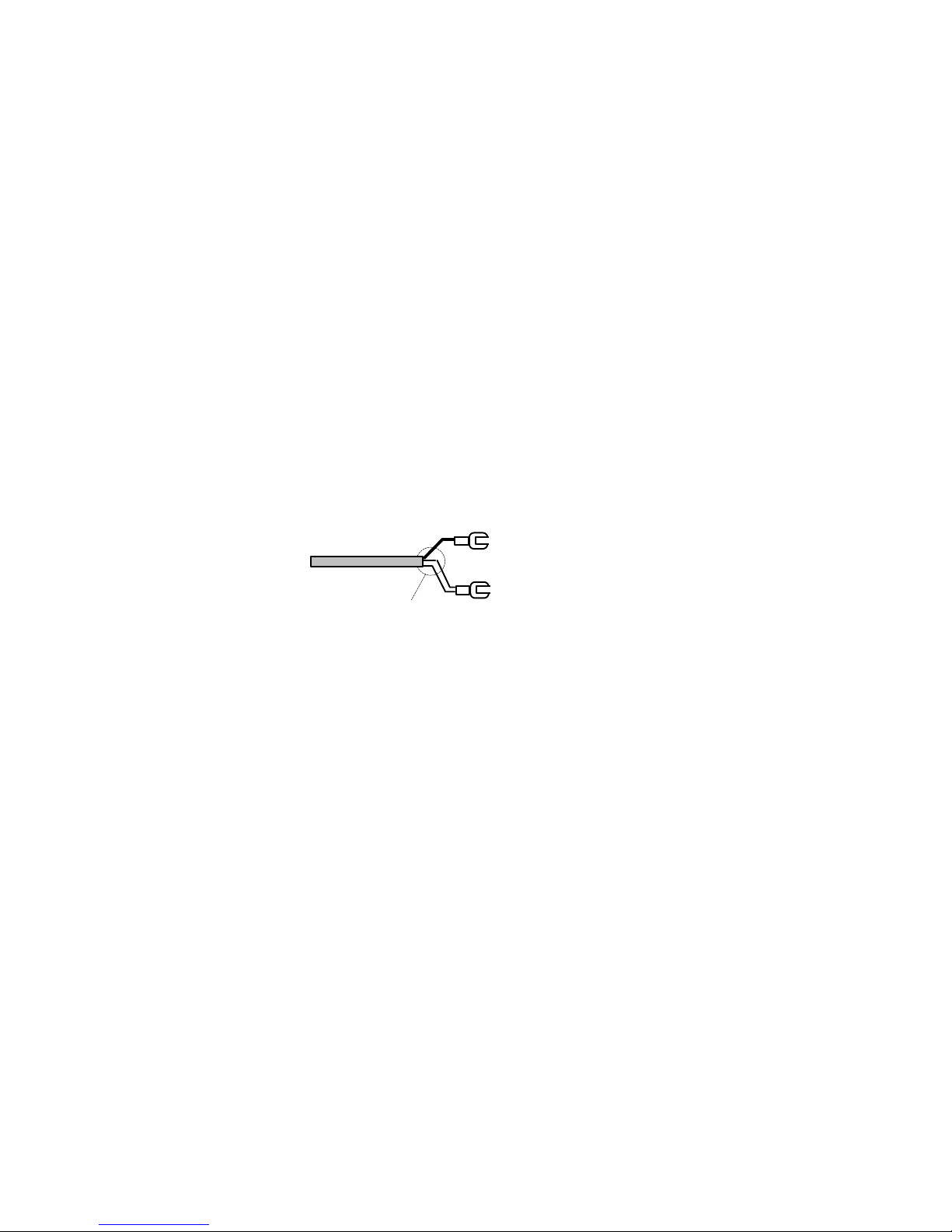
a "no-tune" hairpin impedance matching system, and all elements are cut to exact length at
the factory. No adjustment should be needed for coverage of the 50-MHz SSB band (see
page 8 for FM-segment tuning instructions). Because of its compact size, light weight,
and unique construction, the MFJ-1762 is also a excellent choice for six-meter portable or
"rover" operation. In weak-signal DX applications, two MFJ-1762s may be stacked for
increased capture area and 3-dB additional gain. The MFJ-1762 has been computer
modeled on both ELNECand YAto confirm design integrity, and has been thoroughly
field tested in northern climates for winter survivability.
Typical Specifications:
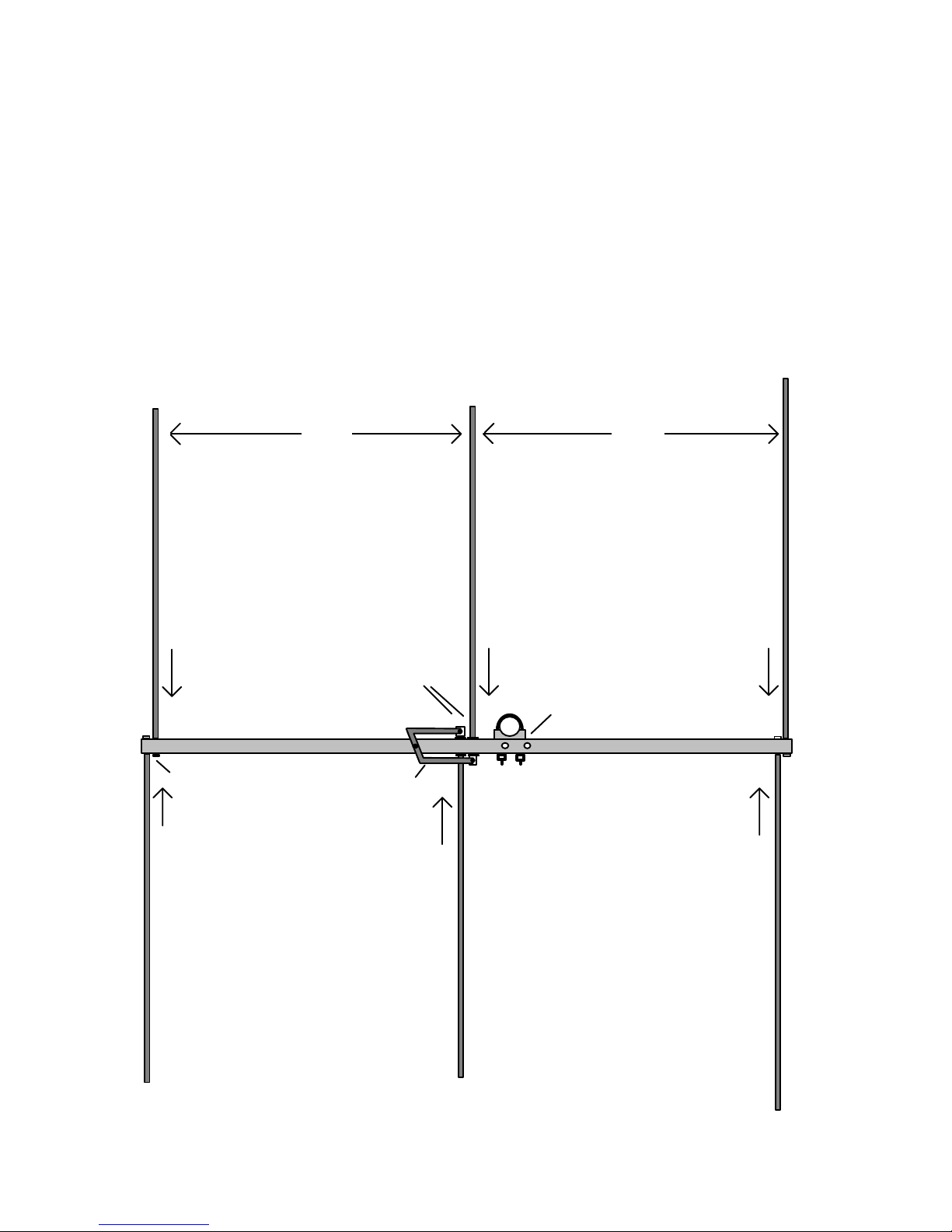
Boom length......................6'
Turning Radius..................5' 8"
Longest Element...............117-1/2"
Weight..............................2.5 Lbs.
Feed Impedance...............50Ω
Resonant Frequency..........50.3 MHz
1.5:1 VSWR Bandwidth...1.7 MHz
Forward Gain....................6.0 dBd (8.2 dBi)
Front-to-Rear Ratio........>18 dB measured
Maximum Power...............150 Watts
Safety Precautions: Before assembling, please read the following safety notice:
This antenna is an electrical conductor--do not handle or mount near power lines, service
entrances, or other dangerous power sources. Mount out of the reach of adults, children,
and animals. Antenna elements develop lethal voltages and may cause severe RF burns
during transmitter operation. For lightning protection, always ground your supporting
mast to two or more outdoor ground rods. Disconnect the feedline from your radio when
not in use. Do not expose pacemakers or other bio-medical equipment to strong RF
radiation. To avoid personal injury or damage to the antenna, plan all mechanical aspects
of your installation carefully. Avoid handling heavy or unwieldy masts by yourself, and
make sure a second person is available to assist you in an emergency. Never work on a
roof or climb a tower alone!

MFJ-1762 Parts List: To begin, confirm that all necessary parts have been supplied with
your antenna package:
[ ] 1 - 6' x 1-1/8" OD boom
[ ] 2 - 54" x 1/4" OD element section (director)
[ ] 2 - 54-1/2" x 1/4" OD element section (driven element)
[ ] 2 - 59-1/4" x 1/4" OD element section (reflector)
[ ] 1 - 5/16" x 1/4" OD spacer
[ ] 1 - hairpin inductor
[ ] 2 - "L" bracket
[ ] 1 - #8 x 1/2" sheet-metal screw
[ ] 6 - 1/2" x 10-32 screw
[ ] 2 - 1/2" x 6-32 screw
[ ] 2 - 6-32 nut
[ ] 2 - 6-32 flat washer
[ ] 2 - 6-32 lock washer
[ ] 4 - Insulated polyethylene element-mounting grommets
[ ] 2 - #6 solder lug
[ ] 1 - 1 - U-bolt mounting hardware kit (U-bolt, mast clamp, nuts)
[ ] Tube of Locktite
If any parts are damaged or omitted, please contact MFJ at (601) 323-0549 to arrange for
replacement.
Tools: You'll need a selection of common household tools to construct your antenna:
Phillips-head screw driver (#2)
Straight-blade screw driver
Pliers
Utility knife or Ex-actoknife with #11 blade
Soldering Set-up
Suggested Antenna Materials:
RG8-M Coax (also RG59 if stacking antennas)
Sealant (Seal-All ) or equivalent
Plastic electrical tape
Suggested Test Equipment:
MFJ-259 RF Analyzer or VSWR bridge

Construction:
[ ] Begin by laying the boom on a flat surface. Find the driven-element holes and the two
sets of mast-mount holes (one for vertical and one for horizontal mounting). The mast-
mount holes are toward the reflector end of the antenna. Identify the director and
reflector ends of the boom before starting assembly.
[ ] Find two (2) 54" director element sections and identify the tapped end of each. Insert
the tapped ends into the 1/4" holes drilled at the director end of the boom. Secure each in
place with 10-32 screws. If you do not anticipate disassembling your beam, apply a drop
of Locktite to each screw. Grip the element section gently with pliers when tightening.
Director Driven Element Reflector
Hairpin Inductor
35-1/4" 35-1/4"
Boom
Mounting Clamp
#10 Screw
107" tip-to-tip 108-1/4" tip-to-tip 117-1/2" tip-to-tip
Driven Element
Mounting Holes Mast

[ ] Find two (2) 59-1/4" reflector element sections and repeat the same mounting
procedure at the back end of the antenna.
Element
#10 screw
Boom Boom
Element
"L" Bracket
#10 Screw
Insulating Grommet
Driven Element Mounting Detail
Director, Reflector Mounting Detail
[ ] Find four (4) black polyethylene insulating grommets and snap one into each driven-
element mounting hole (do not confuse these holes with the U-bolt mounting holes).
[ ] Locate the two remaining element sections (54-1/2" each) and slip the tapped end of
each through the driven-element insulating grommets.
[ ] Using 10-32 screws, install a "L" bracket on each driven element section as shown in
the construction detail. Apply Locktite to the screws and secure firmly in place, using
pliers to gently grip the element.
[ ] Locate the aluminum hairpin inductor and install as shown below, using a #8 sheet
metal screw and the 5/16" x 1/4" OD spacer. Note that the end mounting holes on the
hairpin should align with the driven element "L" brackets.
Hairpin Inductor
Element
#6-32 Mounting Screw
"L" Bracket
Boom
Insulating Grommet
#8 x 1/2" SM Screw
5/16" spacer
Hairpin Mounting Detail
Boom
Hairpin
5/16" Spacer
Element
#6-32 Mounting Screw
#8 x 1/2" SM Screw

[ ] Temporarily fasten each "L" bracket to an end of the hairpin inductor with #6
hardware. The coaxial feedline will be connected to these points later on.
[ ] Temporarily install the mast-mounting hardware (U-bolt can go on either way).
This completes initial mechanical assembly. Check all fasteners for tightness.
Feedline Installation:
For coax runs up to 70 feet, we recommend using RG8M (or mini-8) 1/4" diameter foam
coax. This light-weight cable is available through most amateur radio dealers and is
available in Radio Shack stores nationwide. RG8M performs well at 50-MHz and will
handle 150 Watts with a reasonable margin of safely. Use the following steps to prepare
your feedline:
[ ] Strip back the outer insulation 1" and prepare the two conductors as pigtails--as
shown in the diagram below.
RG8M Lugs
Sealant
[ ] Install a lug on each pigtail (crimp-type lugs should be crimped and soldered). Pigtail
length should not exceed 1-1/4"--including the lug. Excessively-long pigtails will
detune the matching system.
[ ] Apply 2-3 thin coats of Seal-Allto the exposed braid to retard water migration into
the cable. If Seal-All is not available, use a rubberized contact cement or a silicon sealer.
Allow sealant to dry thoroughly before handling the feedline.
[ ] Connect each coax pig-tail to a feedpoint stud using the #6 hardware provided (do not
use Locktite on these connections). Note that the hairpin is installed on the bottom (or
earthward) side of the boom. When installing the MFJ-1762, the hairpin should be on the
ground side and your coax should drop directly below the hairpin.
Balun: The MFJ-1762 driven element is balanced. In order to prevent unwanted
radiation from the feedline, we suggest installing a balun at the feedpoint. This need not
be an elaborate or expensive addition--you can make a simple and effective choke-type
balun using the feedline itself. To do this, form a 5-turn coil of RG8M just below the
feedpoint using about 6' cable. Tape the coils together tightly with electrical tape and
secure them to the mast. As an alternative, install three (3) FB43-5621 ferrite cores on the
feedline at the feedpoint. Be sure to secure your feedline to the mast with electrical tape
to provide stress relief at the feedpoint.

Horizontal Mounting: The MFJ-1762 presents about the same mast-loading as a small
TV antenna. This means you can erect it high and in the clear using standard TV mast,
roof or chimney-mounting hardware, and a light-duty rotator. To avoid property damage
or injury, plan your installation carefully and follow the same safety guidelines that apply
to any TV-antenna installation. Be especially careful not to bend or mis-align elements
when raising the mast. If you stack-mount the MFJ-1762 with other antennas, allow 5'
vertical spacing between higher-frequency Yagis and 10' spacing between lower-frequency
Yagis. Mounting the MFJ-1762 (or any Yagi) too close to existing antennas may distort
the pattern--or raise the launch angle of your signal and compromise performance.
Vertical Mounting: The MFJ-1762 may also be mounted vertically for FM (or for West
Coast SSB) operation. When mounting a single antenna vertically, precautions are needed
to ensure that the mast and feedline do not upset the antenna's VSWR and radiation
pattern. In order to prevent the mast from detuning the driven element, we recommend
using a 8' fiberglass "painter's pole" as a mast. This will provide a strong RF-insulated
support. Fiberglass poles are available at most large home-care centers. A wooden closet
pole will also work--if weather-proofed with a uV-resistant finish. To prevent the feedline
from detuning the driven element, run your coax down the boom to the reflector end, then
let it drop down behind the reflector and below the rotor. If needed, use a short length of
wooden dowel to extend the boom--this will keep the coax from hitting (and detuning) the
reflector. Note that these precautions are not needed if you use a stacked pair of vertical
beams. In this case, the vertical mast will be located mid-way between the antennas and
will not interfere. A stacked pair is always preferable for vertical installations.
Single Vertical Mount Stacked Vertical Mount
Fiberglass Pole
Stacking Two MFJ-1762s: For best stacking performance, use 5/8-wave antenna
separation. In most installations, a single 12' x 1-1/4" length of thin-wall 6061 aluminum
mast may be used to support both antennas. For horizontal stacks, the first antenna
should be mounted as close as possible to the rotor, and the second mounted at the top of
the mast. This will provide approximately 11' 6" of spacing. In vertical installations, a 10'
mast may be substituted with only a minor loss in gain with both antennas mounted at the
extreme ends of the pipe.

In order to feed two antennas with 50Ωline, you'll need to make a simple phasing and
matching harness. The harness is made from readily-available 75Ωline. Either solid or
foam-dielectric RG59 is suitable for this purpose. Prepare your harness as follows:
[ ] Cut one (1) electrical-wavelength of RG59. Be sure to use the correct velocity factor
for your particular cable (155-5/16" for 0.66 VF solid dielectric and 186" for 0.79 VF
foam cable). If your cable has a different VF (velocity Factor), use the formula:
Length in Inches
=
11800
x VF
/
Freq
.
in MHz
[ ] Install three (3) FB43-5621 ferrite sleeves at each end of the cable.
[ ] Prepare pigtails with lugs at each end (see previous instructions for RG8M).
[ ] Cut the RG59 1/4-way down its total length and install PL-259's (at 38'3/4" for 0.66
VF solid or at 46-1/2" for 0.79 VF foam).
[ ] Splice the RG59 back together using a coaxial type "T" adapter--this becomes the
antenna array's 50-Ohm feedpoint.
[ ] Connect pigtail ends to the antennas. Note that this "off-center fed" harness shifts
signals 180-degrees out of phase. To correct for this, be sure to transpose pigtail
connections at the second antenna. If you don't do this, the yagis will be fed out-of-
phase and signals will cancel rather than add! You must install the harness as
shown below:
50-Ohm Feed
RG59
RG8X
Top Antenna
Bottom Antenna
Harness
Portable Operation with the MFJ-1762: Although designed for permanent roof-top
installations, your MFJ-1762 makes an ideal portable antenna. Its unique construction
permits you to remove the elements in less than a minute for easy storage or travel. To
prepare for transport, simply remove the six #10-32 element mounting screws and detach
each element sections from the boom. The feedline and hairpin assembly may remain
attached. If you remove the U-bolt assembly, elements may be stowed inside the boom.

Tuning the MFJ-1762 for FM Sub-band Operation:
The MFJ-1762 is easily retuned for operation in the FM portion of the six-meter band. To
do this, simply re-cut the element sections as shown below using a hacksaw or tubing
cutter. Be careful not to cut the threaded ends when shortening elements!
[ ] Reflector sections, cut for 56-3/4" each.
[ ] Driven element sections, cut for 52-3/8" each.
[ ] Director sections, cut for 51-3/4" each.
This will provide minimum VSWR near the 52.525-MHz FM-simplex calling frequency,
and should provide low VSWR on most 6-Meter FM-repeater input frequencies.
In Case of Difficulty: If you experience difficulty with your MFJ-1762, please check out
the following possibilities before contacting the factory:
High VSWR or Intermittent operation:
[ ] Inspect all connectors for a broken lead, water, ice, severe corrosion, or dirt.
[ ] Inspect coax for kinks, chaffing, crushed areas, breaks in jacket, water infusion, etc.
[ ] Inspect the antenna for loose or broken elements, broken coax pigtail, or debris.
[ ] Check in-line devices such as amplifiers, coax switches, VSWR meters, etc.
[ ] Check balun sleeves for damage from excessive RF heating.
No Sensitivity, Poor directivity:
[ ] Improper phasing (stacked beams only).
[ ] Extreme build up of ice and snow.
IMPORTANT NOTE: Rain, snow, or ice accumulating on antenna elements normally
increases VSWR by lowering the antenna's resonant frequency. Precipitation detuning is
normal for all VHF Yagis, and the MFJ-1762 is cut approximately 200 kHz high in
frequency to help compensate for this effect in wet weather.
The MFJ-1762 is covered by MFJ's exclusive "no matter what" 1 year warranty. If your
antenna does not work properly and a thorough inspection fails to identify the problem,
please contact the factory for further assistance. To contact MFJ's Tech Hotline, call
(601) 323-0549. Be sure to have the manual and a complete description of the difficulty
handy so that you can answer any questions.
Table of contents
Other MFJ Antenna manuals

MFJ
MFJ MFJ-1756 User manual

MFJ
MFJ Legal Limit IntelliTuner MFJ-998RT User manual

MFJ
MFJ MFJ-1903 User manual

MFJ
MFJ MFJ-1742 User manual

MFJ
MFJ 1777 User manual

MFJ
MFJ MFJ-918BP User manual

MFJ
MFJ MFJ-1625 User manual

MFJ
MFJ 1779B User manual

MFJ
MFJ Octopus Antenna MFJ-2100 User manual

MFJ
MFJ MFJ-1770 User manual