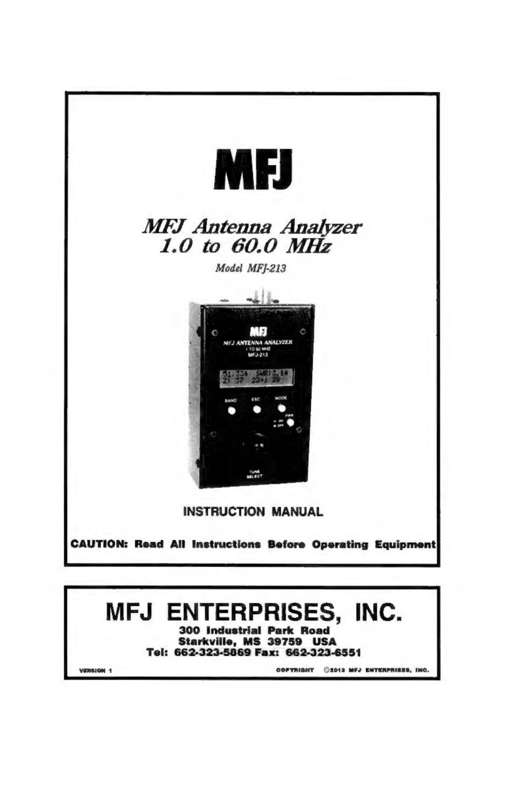
MFJ MFJ-213 User manual

ME)
MEFJ
Antenna
Analyzer
1.0
to
60.0
MHz
Model
MFJ-213
INSTRUCTION
MANUAL
CAUTION:
Read
All
Instructions
Before
Operating
Equipment
MFJ
ENTERPRISES,
INC.
300
Industrial
Park
Road
Starkville,
MS
39759
USA
)2-323-5869
Fax:
662-323.
Tel:
66:
6551
CopymianT
2013
MS
ENTERPRIBES,
INC.

MFJ-213
HF/VHF/UHF
Antenna
Analyzer
Instruction
Manual
DISCLAIMER
Information
in
this
manual
is
designed
for
user
purposes
only
and
is
nof|
intended
to
supersede
information
contained
in
customer
regulations,
technical
manuals/documents,
positional
handbooks,
or
other
official
publications.
The
copy
of
this
manual
provided
to
the
customer
will
not
be
updated
to
reflect
current
data.
Customers
using
this
manual
should
report
errors
or
omissions,
recommendations
for
improvements,
or
other
comments
to
MFJ
Enterprises,
300
Industrial
Park
Road,
Starkville,
MS
39759. Phone:
(662)
323-5869;
FAX:
(662)
323-6551.
Business
hours:
M-F
8-4:30
CST.
Version
1
ii
©
2012
MFI
Enterprises,
Inc

MFJ-213
HF/VHF/UHF
Antenna
Analyzer
Instruction
Manual
Contents
1.0
Introduction
me
2.0
Power
Sources
..
2.1
Internal
Batteries.
2.2
External
Power
Supply..
3.0
Operating
Mode...
3.1
Main
Menu
Screen...
3.1.1
Antenna
Analyzer
Mode
(1.Antenna)
3.1.2
Return
Loss
(2.Loss)
3.1.3
L/C
Measurement
Mode
(3.LC-meter)
3.1.4
Li-ion
Battery
Charge
(4.Chr)
3.1.5
Bluetooth
link
(6.BTIk
4.0
Frequency
Selection.
4.1
Variable
Tuning.
4.2
HF-Band
Selection
5.0
Accuracy
Limit
5.1
SWR
Measurements
and
Local
Interference
5.2
Checking
for
Local
Interference.
5.3
Detector
Linearity
and
Accuracy
5.4
Calibration-Plane
Error
5.5
Sign
Ambiguity
(+
j)
6.0
Antenna
Measurement:
6.1
Antenna
Connector:
6.2
SWR
6.3
Measuring
SWR
6.4
SWR,
Bandwidth,
and
Resonanci
6.5
Antenna
Tuning.
6.6
Antenna
matching
6.7
Matching
antennas
through
a
tuner
(.
6.8
Antenna
Impedance
Readings
.
6.9
Unpredictable
SWR.
7.0
Advanced
Functions.
7.1
Stimulus
Generator
as
a
Signal
Sourc
7.2
Measuring
Unknown
Capacitance.
7.3
Measuring
Unknown
Inductance.
7.4
Determining
Cable
Velocity
Factor
7.5
Tuning
a
%4-Wave
or
'4-Wave
Coaxial
Stub..
7.6
Checking
Coax
Cable.
7.7
Testing
RF
Transformers
..
7.8
Checking
HF
Baluns
..
NOTES:
8.0
Quick
Guide
to
Analyzer
Controls
and
Functions
.
Powe
Power
Up:
Main
Menu
Screen:
Set
Up
Stimulus
Frequency:
Return
Loss
Function
(2.Loss):
LIC
Function
(3,LC-mets
Charging
Function
(4.Chr
Technical
Assistance
..
12
MONTH
LIMITED
WARRANT"
2
Version
1
iii
©
2012
MFI
Enterprises,
Inc

—
MFJ-213
HF/VHF/UHF
Antenna
Analyzer
Instruction
Manual
1.0
INTRODUCTION
Important:
Read
Section-2
before
attempting
to
use
your
analyzer
--
applying
incorrect
operating
voltages
could
result
in
permanent
damage!
Also,
never
apply
a
DC
voltage
to
the
antenna
connector.
General
Description:
The
MFJ-213
is
a
self-contained
handheld
RF
analyzer
that
performs
the
following
diagnostic
functions:
SWR
(1:1
to
9.9:1)
Complex
Impedance
(Z
=
R
+
jX)
Impedance
Magnitude
(Z
in
Q)
Return
Loss
(in
dB)
Cable
Loss
(in
dB)
Capacitance
(in
pF)
Inductance
(in
uH)
The
MFJ-213
also
generates
a
0-dBm
RF
signal
that
may
be
used
to
check
receivers,
networks,
amplifiers,
and
antenna
patterns.
Operating
range
is:
HF:
1.00
—
60.00
MHz
The
MFJ-213
uses
a
DDS
signal
generator
giving
a
stable
0dBm
signal
tuned
by
a
rotary
encoder.
Measurements
are
displayed
on an
easy-to-read
LCD
screen
with
optional
backlighting.
Power
is
supplied
by
internal
AA
cells,
an
18650
Li-ion
cell
or
by
a
regulated
12-VDC
external
power
source
(not
included).
Weighing
just
over
1.3
pounds,
the
MFJ-213
package
fits
comfortably
in
one
hand
for
convenient
bench
work
or
on-the-fly
testing
in
the
field.
Operation
is
simple,
but
you
will
need
to
read
the
manual
to
learn
all
of
the
unit's
features
and
functions.
The
more
you
know
the
more
valuable
it
will
become
as
a
diagnostic
tool.
Version
1
1
©
2012
MFI
Enterprises,
Inc

MFJ-213
HF/VHF/UHF
Antenna
Analyzer
Instruction
Manual
2.0
POWER
SOURCES
The
MFJ-213
may
be
powered
with
internal
AA
batteries,
18650
Li-ion
cell
or
with
an
external
DC
supply.
To
avoid
needless
damage
and
ensure
top
performance,
please
follow
the
guidelines
below
when
choosing
a
voltage
source.
2.1
Internal
Batteries
To
access
the
jumpers
and
battery
compartments,
remove
all
four
screws
securing
the
analyzer's
back
cover
and
carefully
open
the
case.
To
operate
the
MFJ-213
on
batteries
put
the
EXT
PWR-BAT
jumper
on
the
PC
board
in
the
BAT
position
and
install
the
batteries.
The
MFJ-213
can use
either
AA
cells
or
a
18650
LI-ion
cell
to
power
it
on
batteries.
AA
Battery
power
requires
3
(three)
AA-size
1.5-volt
alkaline
cells.
Batteries
are
installed
in
a
fully
encased
3-cell
plastic
tray
mounted
inside
the
analyzer
enclosure.
Slide
the
battery
box
covers
sideways
to
unlatch,
and
then
lift
vertically
to
expose
the
cells.
When
replacing
old
batteries,
be
sure
to
follow
the
manufacturer's
environmental
guidelines
for
safe
disposal.
For
longest
battery
life,
always
replace
with
a
matched
set
of
factory-fresh
cells.
The
MFJ-213
will
not
charge
batteries
in
the
AA
cell
pack.
Do
not
use
rechargeable
AA
cells
in
the
pack.
The
battery
pack
plugs
into
the
socket
on
the
bottom
of
the
PC
Board.
The
MFJ-213
can
also
hold
an
optional
rechargeable
18650
battery
and
charger
board.
This
battery
is
inserted
into
a
holder
that
is
placed
at
the
bottom
of
the
case.
Disassemble
the
case
as
listed
above
and
insert
the
battery
into
the
holder
making
sure
the
polarity
is
correct.
This
battery
is
recharged
from
the
external
supply
through
a
special
charging
circuit
(optional)
that
plugs
into
the
MFJ-213.
Charging
time
is
about
10
hours
using
the
MFJ-1312B.
See
the
section
on
the
charging
function
below
for
charging
the
battery.
The
battery
holder
has
a
circuit
built
in
to
prevent
the
battery
from
discharging
below
the
minimum
safe
voltage.
If
the
battery
has
discharged
to
that
point
or
a
new
battery
has
been
put
in
the
battery
must
Version
|
2
©
2012
MFJ
Enterprises,
Inc

MFJ-213
HF/VHF/UHF
Antenna
Analyzer
Instruction
Manual
be
charged
above
that
point
resetting
the
circuit
before
a
Li-ion
battery
will
function
in
the
MFJ-213.
2.2
External
Power
Supply
To
operate
the
MFJ-213
on
an
external
power
supply
plug
in
an
external
power
supply
onto
the
EXT
PWR
jack
on
the
top
of
the
unit..
Powering
the
MFJ-213
externally
requires
a
well-filtered
12V
DC
supply
such
as
the
MFJ-1312D
capable
of
delivering
12
to
15
VDC
under
varying
load
conditions.
Current
drain
ranges
from
30
mA
to
180
mA,
depending
on
operating
mode,
frequency
range,
and
whether
or
not
the
display
backlight
is
on.
The
unit's
external
power
jack
is
located
on
the
front
panel
and
accepts
a
standard
2.1-mm
power
plug.
Positive
voltage
(+)
must
be
applied
to
the
connector's
center
pin.
Important Warnings:
Reverse
polarity
or
excessive
voltage
could
permanently
damage
the
MFJ-213!
To
avoid
damage:
1.
Never
connect
an
AC
transformer
or
positive-ground
power
source
2.
Never
install
or
remove
batteries
with
external
power
connected
3.0
OPERATING
MODE
Once
you
have
suitable
power
(battery
or
external),
you're
ready
to
explore
the
analyzer's
basic
operating
features.
Begin
by
pressing
the
red
PWR
button
on.
BAND
ESC
MODE
PWR
ON
morF
3.1
Main
Menu
Screen
The
individual
functions
are
listed
on
the
main
screen
and
are
selected
by
rotating
the
TUNE/SELECT
knob
then
pushing
the
TUNE/SELECT
knob
to
select
the
function.
To
exit
from
any
of
the
functions
press
the
ESC
button
to
return
to
the
Main
Menu
Screen.
»BT1k
1
ard
Fr
Version
1
3
©
2012
MFI
Enterprises,
Inc

MFJ-213
HF/VHF/UHF
Antenna
Analyzer
Instruction
Manual
3.1.1
Antenna
Analyzer
Mode
(1.Antenna)
The
MFJ-213
may
be
used
to
measure
the
impedance,
complex
impedance
and
SWR
of
an
antenna
connected
to
the
antenna
connector
in
this
function.
There
are
3 sub-modes
selected
with
the
MODE
button.
Default
is
the
impedance
measurements.
The
next
mode
reads
the
external
power
supply
voltage
(Pv)
when
connected
to
an
external
charger
and
the
battery
voltage
(Bv)
when
batteries
are
installed.
When
the
external
supply
or
internal
batteries
are
not
installed
then
those
numbers
are
not
valid.
The
third
mode
is
a
measurement
of
external
noise
that
can
cause
erroneous
readings.
Stimulus
Frequency
=A
\plex
Taianee
3.1.2
Return
Loss
(2.Loss)
Impedance
Com
This
function
on
the
MFJ-213
reads
the
return
loss
and
SWR
of
an
antenna
connected
to
the
antenna
connector.
There
are
two
modes
in
this
function.
The
default
is
return
loss
and
the
next
mode
selected
by
pressing
the
MODE
button
is
cable
loss.
The
cable
loss
is
measured
by
connecting
the
cable
to
the
antenna
connector
and
leaving
the
other
end
open
or
unterminated.
This
mode
is
for
50
ohm
cables.
Stimulus
Frequency
Stimulus
Frequency
Return
Loss
SWR
3.1.3
LIC
Return
Loss
SWR
Measurement
Mode
(3.LC-meter)
The
MFJ-213
may
be
used
to
measure
the
value
of
unknown
capacitors
and
inductors.
To
measure
L/C
values,
select
this
function,
connect
the
device
to
be
tested
to
the
antenna
jack
and
follow
the
procedure
outlined
below:
Measure
Capacitance
If
the
display
does
not
indicate
Xc
in
the
top
line
and
C=
in
the
second
line
press
the
MODE
button
till
this
mode
is
selected.
The
capacitance
at
that
frequency
is
displayed
and
the
capacitive
reactance
is
displayed
to
the
far
right.
Stimulus
Frequency
Mb
C
FF
13
Capacitance
Reactance
Measure
Inductance
Version
|
4
©
2012
MFJ
Enterprises,
Inc

MFJ-213
HF/VHF/UHF
Antenna
Analyzer
Instruction
Manual
Press
the
MODE
button
till
the
display
indicates
XL
in
the
top
line
and
L=
in
the
second
line
this
mode
is
selected.
The
inductance
at
that
frequency
is
displayed
and
the
inductive
reactance
is
displayed
to
the
far
right.
Stimulus
Frequency
18,
oi
MHz
L=
WH
Inductance
SWR
3.1.4
Li-ion
Battery
Charge
(4.Chr)
Charging
the
Li-ion
battery
is
done
using
a
special
charger
(optional)
plugged
into
the
MFJ-213.
The
external
power
supply
must
first
be
plugged
into
the
unit
for
the
charger
to
function.
Note
just
plugging
the
external
supply
will
not
charge
the
battery.
To
charge
the
Li-ion
battery
if
installed
you
rotate
the
TUNE/SELECT
knob
to
this
function
then
press
the
TUNE/SELECT
knob
in.
The
charging
circuit
will
come
on
displaying
CHARGING
and
will
run
till
fully
charged.
3.1.5
Bluetooth
link
(6.BTIk)
This
is
an
option
that
is
plugged
into
the
MFJ-213
allowing
you
to
link
the
MFJ-213
to
an
android
device.
See
the
installation
instructions
with
this
option
on
installation
and
use.
4.0
FREQUENCY
SELECTION
The
MFJ-213
covers
the
HF
region
(1.5-60
MHz)
4.1
Variable
Tuning
The
MFJ-213
tunes
continuously
from
1.500
to
60.000
MHz
by
turning
the
TUNE/SELECT
knob.
The
tuning
speed
can
be
selected
by
pushing
in
the
TUNE/SELECT
knob
to
select
which
digit
to
increment.
The
frequency
displayed
on
the
LCD
display
will
have
a
bar
under
the
digit
that
will
be
incremented
and
pushing
in
the
knob
advances
the
bar
to
the
next
digit
between
1
KHz
and
|
MHz
in
the
Analyzer
mode
and
10Hz
and
1
MHz
in
the
other
modes.
Stimulus
Frequency
a
You
can
select
each
of
the
amateur
bands
instead
of
turning
the
tuning
knob
by
pressing
the
BAND
button.
-
88
Frequency
Step
Marker
4.2
HF-Band
Selection
Version
1
5
©
2012
MFI
Enterprises,
Inc

MF/J-213
HF/VHF/UHF
Antenna
Analyzer
Instruction
Manual
Before
moving
on
to
the
next
section,
take
time
to
review
the
MFJ-213’s
basic
set-up
procedures.
Operation
becomes
second
nature
quickly,
but
should
you
need
it,
there’s
a
supplemental
"quick
guide"
in
the
back
for
reference
(Section
8.0).
The
remainder
of
the
manual
will
focus
on
general
instructions
and
helpful
tips
for
making
accurate
measurements.
5.0
ACCURACY
LIMITS
The
MFJ-213
will
serve
as
your
“eyes
and
ears”
when
working
with
RF
systems,
and
it
can
deliver
results
that
rival
units
costing
thousands
of
dollars.
However,
all
handheld
analyzers
share
certain
limitations,
and
being
aware
of
them
will
help
you
to
achieve
more
meaningful
results.
5.1
SWR
Measurements
and
Local
Interference
The
MFJ-213
(and
other
hand-helds)
uses
a
broadband
diode
detector
that
is
open
to
receiving
signals
across
the
entire
radio
spectrum.
Most
of
the
time,
the
unit's
built-in
stimulus
generator
is
powerful
enough
to
overcome
any
lack
of
front-end
selectivity
and
override
stray
pickup.
However,
a
powerful
transmitter
located
nearby
could
inject
enough
RF
energy
into
the
detector
to
disrupt
readings.
If
this
condition
occurs,
performance
will
become
erratic
and
SWR
readings
may
appear
higher
than
they
really
are.
5.2
Checking
for
Local
Interference
Unlike
many
analyzers,
the
MFJ-213
has
an
onboard
function
for
identifying
local
interference.
In
the
1.Antenna
function
simply
switch
to
the
third
mode
and
note
the
readings
you
obtain
with
the
antenna
connected.
If
a
strong
signal
(>100)
registers
on
the
display,
then
suspect
interference.
If
the
interfering
source
can't
be
turned
off
or
your
antenna
can't
be
moved
to
a
different
location,
you
may
need
to
use
a
station
transceiver
and
a
thru-line
directional
Wattmeter
to
complete
the
adjustments.
Stimulus
Frequency
Noise
level
Noise
indicator
5.3
Detector
Linearity
and
Accuracy
Diode
detectors
typically
become
non-linear
at
very
low
voltages.
Because
of
diode
non-linearity,
it's
not
uncommon
for
two
identical
analyzers
to
show
slightly
different
readings
when
checking
a
load
with very
low
SWR
(or
low
RF-return
voltage).
For
example,
one
analyzer
may
read
1.2:1
while
another
reads
1.1:1
when
checking
the
same
antenna.
The
MFJ-213
is
electronically
compensated
to
minimize
detector
error,
but
be
aware
of
the
potential
for
minor
differences.
Version
|
6
©
2012
MFI
Enterprises,
Inc

MFJ-213
HF/VHF/UHF
Antenna
Analyzer
Instruction
Manual
5.4
Calibration-Plane
Error
The
analyzer’s
calibration
plane
is
the
point
of
reference
where
all
measurements
have
the
greatest
accuracy
(gain
reference=0
dB,
phase
shift
=
0-degrees).
For
basic
hand-held
units
like
the
MFJ-213,
the
calibration
plane
is
fixed
at
the
antenna
connector.
As
such,
any
measurement
made
through
a
cable
will
displace
the
load
from
the
calibration
plane
and
introduce
some
amount
of
error.
For
SWR
readings,
error
is
mainly
caused
by
losses
in
the
cable.
Specifically,
SWR
will
read
somewhat
lower
through
a
length
of
cable
than with
the
analyzer
connected
directly
to
the
direct
load
because
the
forward
and
reflected
stimulus
signals
are
attenuated
in
the
feedline.
The
more
loss
there
is
in
the
cable,
the
greater
the
error.
Most
of
the
time,
this
inaccuracy
isn’t
a
problem
because
the
SWR
you
measure
with
the
analyzer
is
the
same
SWR
the
radio
will
encounter
when
connected.
However,
if
you
wish
to
know
the
antenna’s
actual
feedpoint
SWR
for
documentation
purposes,
the
analyzer
should
be
connected
directly
to
the
feed
point
through
a
short
pigtail.
Calibration-plane
error
has
a
much
more
significant
impact
when
attempting
to
measure
impedance
values
because
of
phase
rotation
in
the
cable.
In
fact,
impedance
readings
can
swing
dramatically,
depending
on
the
cable’s
electrical
length
and
the
severity
of
the
load’s
mismatch
with
reference
to
50
Ohms.
For
accurate
impedance
data,
always
connect
the
analyzer
directly
to
the
antenna
or
device
you're
testing
using
the
shortest
lead
possible.
5.5
Sign
Ambiguity
(+
j)
Most
hand-held
analyzers
(including
the
MFJ-213)
lack
the
processing
capability
to
calculate
the
reactance
sign
for
complex
impedance
(Z
=
R
+
j).
By
default,
the
MFJ-213
displays
a
plus
sign
(+
j)
between
the
resistive
and
reactive
values,
but
this
sign
is
merely
a
placeholder
and
not
a
calculated
data
point.
Although
the
analyzer’s
processor
can’t
calculate
sign,
it
can
often
be
determined
with
a
small
adjustment
of
the
TUNE
control.
To
determine
sign,
TUNE
the
analyzer
up-frequency
slightly
--
(1.)
If
reactance
decreases,
the
sign
is
likely
to
be
(
-
)
and
the
reactance
capacitive
(Xc).
(2.)
If
reactance
increases,
the
sign
is
likely
to
be
(
+
)
and
the
reactance
inductive
(X:).
Version
|
7
©
2012
MFI
Enterprises,
Inc

MFJ-213
HF/VHF/UHF
Antenna
Analyzer
Instruction
Manual
6.0
ANTENNA
MEASUREMENTS
Excellent
tutorials
are
available
in
ARRL
Handbooks
and
other
League
antenna
publications
to
help
you
master
the
art
and
science
of
constructing
and
adjusting
effective
antenna
systems.
Informative
introductory
material
may
also
be
found
on
line,
but
choose
carefully.
Not
all
web
material
is
well
edited
or
accurate
(especially
items
discussed
in
chat
rooms
and
forums).
Here
are
some
general
guidelines
to
help
you
get
started.
6.1
Antenna
Connectors
The
MFJ-213
uses
a
SO-239-female
(or
UHF)
connector.
Stacking
multiple
adapters
together
places
unnecessary
stress
the
analyzer’s
connector
and
increases
the
possibility
of
measurement
error.
6.2SWR
Standing
Wave
Ratio
(SWR),
sometimes
referred
to
as
VSWR,
is
the
most
widely
used
format
for
checking
tuning
error
and
impedance
mismatch
between
antennas
and
radios.
The
MFJ-213
is
calibrated
to
work
on
the
50-
ohm
impedance
standard
used
by
amateur
and
commercial
two-way
equipment
(Zo=50).
Unless
a
different
cable
impedance
is
specified
by
the
antenna
designer
for
matching
purposes,
always
use
50-Ohm
cable
of
known
quality
when
making
up
transmission
lines
and
patch
cables.
WARNING:
Never
apply
external
dc
voltages
or
strong
RF
signals
to
the
analyzer’s
antenna
connector
or
permanent
damage
will
result.
Also,
never
connect
the
output
of
a
transmitter
to
your
analyzer.
6.3
Measuring
SWR
Here
is
the
recommended
procedure
for
the
checking
antenna
SWR
with
the
MFJ-213:
(1.)
Turn
the
unit
ON
and
select
the
Antenna
function
(Section-3).
(2.)
Select
the
desired
Frequency
(Section-4).
(3.)
Connect
the
antenna
to
the
analyzer
(Antenna
connector)*.
(4.)
Rotate
the
Tune
knob
to
find
the
lowest
SWR
reading
and
write
it
down.
(5.)
Rotate
Tune
to
either
side
of
minimum
SWR
and
note
the
2:1
SWR
points.
*When
testing
large
ungrounded
antenna
systems
such
as
HF
dipoles,
momentarily
short
the
feedline
center
pin
to
ground
to
bleed
off
static
buildup
before
connecting
to
the
analyzer.
Version
1
8
©
2012
MFJ
Enterprises,
Inc

MFJ-213
HF/VHF/UHF
Antenna
Analyzer
Instruction
Manual
6.4
SWR,
Bandwidth,
and
Resonance
The
amateur-radio
industry's
standard
for
maximum
SWR
is
2:1.
Most
modern
transceivers
operate
safely
and
deliver
full
power
within
this
mismatch
range.
The
antenna
bandwidth
is
the
frequency
interval
between
its
two
2:1
SWR
points.
This
specification,
along
with
minimum
SWR
and
minimum
SWR
frequency,
is
often
included
on
antenna
specification
sheets.
Note
that
minimum
SWR
is
sometimes
wrongly
confused
with
resonant
Srequency.
The
technical
definition
for
resonance
is
the
frequency
where
inductive
and
capacitive
reactance
cancels,
leaving
a
purely
resistive
load
(4
=
0).
The
minimum
SWR
and
resonant
frequencies
may
be
close,
but
they
rarely
coincide.
6.5
Antenna
Tuning
Where
possible,
make
adjustments
to
your
antenna
that will
yield
SWR
readings
under
2:1
over
the
frequency
range
where
you
normally
operate.
If
the
minimum-SWR
frequency
measures
low
in
the
band
(or
below
the
band
edge),
your
antenna
is
probably
too
long
and
will
need
to
be
shortened.
If
the
Minimum
SWR
frequency
is
too
high,
it
should
be
lengthened.
To
calculate
the
required
change
in
length:
(1.)
Write
down
the
desired
minimum
SWR
frequency
(ex:
14.200
MHz)
(2.)
Use
the
analyzer
to
measure
the
present
minimum
SWR
frequency
(ex:
14.050
MHz)
(3.)
Divide
the
present
frequency
by
the
desired
frequency
(ex
14.050
+
14.200
=
.989)
(4.)
Multiply
the
present
length
by
the
result
(33.3
feet
x
.989
=
32.94
feet)
Note
that
this
formula
applies
to
full-sized
antennas,
but
not
to
elements
shortened
by
coils,
traps,
or
capacitive
hats.
Version
|
9
©
2012
MFI
Enterprises,
Ine

MFJ-213
HF/VHF/UHF
Antenna
Analyzer
Instruction
Manual
6.6
Antenna
matching
If
your
antenna
doesn’t
exhibit
1:1
SWR
at
the
minimum
SWR
frequency,
then
some
mismatch
is
present
relative
to
50-Ohms.
For
simple
dipoles
and
ground-independent
verticals,
mounting
height
above
ground
may
be
the
primary
cause.
Generally,
it’s
best
to
ignore
SWR
readings
under
2:1
and
mount
these
antennas
as
high
as
possible
where
they’ll
perform
best.
For
antennas
that
feature
adjustable
matching
networks
(Yagis
etc),
SWR
can
usually
be
improved
by
following
the
manufacturer’s
antenna
setup
instructions.
Note
that
matching
and
tuning
settings
may
interact,
so
readjustment
of
both
the
antenna’s
element
length
and
matching
network
may
be
needed
to
obtain
best
results.
6.7
Matching
antennas
through
a
tuner
(ATU)
If
your
antenna
can’t
be
tuned
or
matched
to
an
acceptable
SWR
level
by
making
physical
adjustments,
then
an
external
antenna
tuner
(ATU)
should
be
installed.
The
MFJ-213
may
be
used
in
conjunction
with
the
tuner
to
make
adjustments
without
the
need
to
transmit
test
signals
over
air.
Simply
connect
the
analyzer
to
the
tuner
input
(radio
side)
through
a
short
patch
cable.
Select
the
Analyzer
mode,
set
up
the
Band,
and
Tune
for
the
desired
frequency
of
operation.
Then,
adjust
the
antenna-tuner's
controls
following
the
manufacturer's
recommendations
until
SWR
approaches
1:1.
Remove
the
analyzer,
reconnect
the
radio,
and
the
load
will
be
pre-matched
to
the
radio's
50-Ohm
operating
impedance.
6.8
Antenna
Impedance
Readings
The
MFJ-213
displays
complex
impedance
and
impedance
magnitude
readings
on
the
same
screen
with
the
SWR
reading.
However,
when
measuring
through
coax,
remember
that
the
impedance
readings
are
phase-
shifted
values
appearing
at
your
end
of
the
cable
and
not
the
actual
feedpoint
impedance
of
the
antenna
itself
(Section-5.4).
As
a
“work-around”
strategy,
it’s
possible
to
measure
the
antenna’s
actual
impedance
remotely
if
the
feedline
is
cut
to
an
exact
electrical
half
wavelength.
In
a
half-wavelength
line,
the
phase
shift
is
a
full
360
degrees,
which
electrically
rotates
the
analyzer’s
calibration
plane
back
into
alignment
with
the
load.
However,
this
strategy
only
works
at
one
frequency
and
errors
compound
quickly
if
your
cable
is
multiple
half-wavelengths
long.
As
a
practical
matter,
unless
you
have
an
advanced
working
knowledge
of
transmission-lines,
Smith
charts,
and
impedance
matching
theory,
it’s
best
to
ignore
impedances
and
rely
on
SWR
for
routine
antenna-system
adjustments.
6.9
Unpredictable
SWR
A
change
in
feedline
length
shouldn't
shift
your
antenna's
minimum-SWR
frequency
or
have
much
impact
on
the
SWR
readings.
If
it
does,
suspect
a
significant
mismatch
between
the
antenna
and
coax,
or
more
likely,
poor
Version
1
10
©
2012
MFI
Enterprises,
Inc

$i
MFJ-213
HF/VHF/UHF
Antenna
Analyzer
Instruction
Manual
isolation
between
the
feedline
and
the
antenna.
Isolation
problems
typically
occur
when
unbalanced
coax
line
is
connected
directly
to
a
balanced
element
such
as
a
dipole
or
a
loop,
and
the
outer
surface
of
the
coax
shield
literally
becomes
a
part
of
the
antenna.
If
the
length
of
the
shield
happens
to
presents
a
low
impedance
path,
it
can
load
the
element
significantly
and
shift
the
minimum-SWR
frequency
unpredictably.
It
will
also
introduce
needless
mismatch,
divert
transmitted
RF
back
toward
the
operating
position,
causing
RFI
problems
in
the
residence,
and
increase
unwanted
noise
pickup
in
receive
mode.
The
best
way
to
decouple
the
outer
surface
of
the
shield
from
the
antenna
element
is
with
a
balun.
Current-type
baluns
work
best
because
they
have
higher
power-handling
capability
and
less loss
than
other
types.
An
effective
current
balun could
be
as
simple
as
a
few
loops
of
coax
taped
together
at
the
feedpoint,
but
for
best
common-mode
rejection,
a
Guanella-
style
balun
wound
on
a
ferrite
core
is
recommended.
7.0
ADVANCED
FUNCTIONS
Here
are
some
of
the
MFJ-213
advance
functions.
Note
that
some
of
these
procedures
involve
connecting
component
leads
to
the
unit's
Antenna
connector.
For
these
connections,
we
suggest
making
up
a
very
short
UHF-
male
coaxial
pigtail
or
obtaining
a
UHF
dual
binding
post
adapter
to
prevent
damage
the
center-contact
of
the
analyzer
connector.
7.1
Stimulus
Generator
as
a
Signal
Source
When
operated
in
Analyzer
mode,
the
MFJ-213
generates
a
0
dBm
CW
carrier
(1
mW).
See
section
3.1.1
for
setup
procedures.
Output
will
vary
slightly,
depending
on
frequency
and
operating
voltage,
but
typically
holds
to
within
1-2
dB
of
the
rated
power
level
over
the
analyzer's
frequency
range.
Harmonic
suppression averages
-20
dBc.
A
quarter-wave
stub
or
low-
pass
filter
may
be
installed
if
greater
harmonic
suppression
is
required
for
a
specific
application.
Frequency
stability
and
carrier
purity
are
sufficient
for
testing
filters,
mixers,
low-power
amplifier
stages,
and
for
checking
antenna
patterns
when
a
range
antenna
is
connected
to
the
analyzer
output.
The
stimulus
generator
may
also
be
used
for
producing
lower-level
signals
with
a
suitable
precision
RF
attenuator
installed
in
line.
When
connecting
the
generator
directly
to
active
circuitry,
always
insert
a
coupling
capacitor
to
prevent
DC
voltages
from
back-feeding
into
the
bridge
circuit
and
destroying
the
detector
diodes.
Also,
avoid
connecting
the
stimulus
signal
directly
to
sensitive
preamps
or
receiver
circuits
that
could
be
damaged
by
an
un-
attenuated
1-mW
signal.
Version
1
i
©
2012
MFJ
Enterprises,
Inc

MFJ-213
HF/VHF/UHF
Antenna
Analyzer
Instruction
Manual
7.2
Measuring
Unknown
Capacitance
To
measure
capacitance,
connect
the
unknown
component
to
the
Antenna
connector
(usable
range
is
from
approximately
15
pF
to
1200
pF).
To
enter
the
Capacitance
mode,
begin
with
the
analyzer
at
the
main
menu
and
select
the
LC-meter
function
(see
Section
3.1.3).
The
screen
will
display
the
approximate
value
of
the
unknown
capacitor
in
pF
along
with
the
stimulus
frequency
where
the
measurement
is
being
made.
The
best
accuracy
is
typically
obtained
in
the
4
to
9
MHz
range,
which
may
be
selected
using
the
BAND
button
and
the
TUNE
knob.
Note
that
any
capacitor
and
lead
combination
that
approaches
self-resonance
at
the
stimulus
frequency
will
trigger
the
C
=
Xc
>1.5KQ
message
and
will
be
un-measurable.
Attempt
to
re-measure
at
a
lower
frequency.
7.3
Measuring
Unknown
Inductance
To
measure
inductance,
connect
the
unknown
component
to
the
Antenna
connector.
To
enter
the
Inductance
mode,
begin
with
the
analyzer
at
the
main
menu
and
select
the
LC-meter
function
then
press
the
MODE
button
to
select
the
inductance
mode(see
Section
3.1.3).The
screen
will
display
the
approximate
value
of
the
unknown
inductor
in
uH
along
with
the
stimulus
frequency
where
the
measurement
is
being
made.
The
best
accuracy
is
typically
obtained
in
the
2
to
9
MHz
range,
which
may
be
selected
using
the
BAND
button
and
the
TUNE
knob.
Note
that
any
inductor
approaching
self-
resonance
at
the
stimulus
frequency
will
trigger
the
L
=
X,
>1.5KQ
message
and
will
be
un-measurable.
Try
to
re-measure
at
a
lower
frequency.
7.4
Determining
Cable
Velocity
Factor
If
you
have
coax
cable
with
an
unknown
velocity
factor,
you
can
determine
it
quickly
using
the
following
procedure:
(1.)
Set
the
MFJ-213
up
in
Analyzer
mode
(Section-3)
(2.)
Set the
frequency
to
around
20
MHz
(Section-4)
(3.)
Make
a
1/4-A
stub
from
9
feet
of
the
unknown
cable
and
connect
it
to
the
analyzer
(other
end
open)
(4.)
Rotate
Tune
for
minimum
impedance
magnitude
reading.
Write
down
the
frequency
(in
MHz)
(5.)
Divide
246
by
this
frequency
to
find
the
free-space
1/4-A
wavelength
in
feet
(L
=
246
+f
MHz)
(6.)
Divide
9
(the
actual
length)
by
free-space
1/4-
wavelength
to
get
the
Velocity
Factor
(VF
=9
+L)
Note
that
there
is
nothing
magical
about
the
9-foot
stub
length,
other
than
it
falls
conveniently
within
the
limits
the
tuning
range.
Other
lengths
could
be
Version
1
12
©
2012
MFI
Enterprises,
Inc

MFJ-213
HF/VHF/UHF
Antenna
Analyzer
Instruction
Manual
used.
Shorter
stubs
will
yield
poorer
accuracy
and
long
ones
may
needlessly
waste
useful
cable.
7.5
Tuning
a
'4-Wave
or
'2-Wave
Coaxial
Stub
To
accurately
tune
a
coaxial
stub,
begin
by
calculating
the
free-space
length
at
the
stub's
intended
operating
frequency:
For
1/4-A
in
inches
=
295]
+
MHz
For
1/4-A
in
feet
=
246
+
MHz
For
1/2-A
in
inches
=
5902
+
MHz
For
1/2-A
In
feet
=
492
+
MHz
Next,
multiply
the
free-space
length
times
your
cable's
velocity
factor.
Finally,
add
at
least
10%
to
this
length
for
a
margin
of
error
(better
too
long
than
too
short).
Cut
the
cable
to
this
initial
length.
Connect
one
end
of
the
cable
to
the
analyzer's
Antenna
connector.
For
a
1/4-A
stub,
leave
the
far
end
open.
For
a
1/2-A
stub,
short
the
far
end.
Next:
(1.)
Set
the
MFJ-213
to
Antenna
mode
(Section-3)
(2.)
Initially,
set
the
Band
and
Tune
for
the
desired
stub
frequency
(Section-
4)
(3.)
*Tune
down
in
frequency
to
find
lowest
impedance-magnitude
reading
(a
1/4-A
open
or
a
1/2-A
short
look
like
a
short
or
low
impedance
load).
(4.)
Write
your
measured
frequency
down.
(5.)
Divide
the
measured
frequency
by
the
desired
stub
frequency
to
obtain
a
correction
factor
(6.)
Multiply
the
present
stub
length
by
the
correction
factor
to
get
the
desired
stub
length.
(7.)
Re-cut
the
cable
to
that
length.
*Note
that
the
impedance
value
may
not
drop
to
zero,
but
it
will
begin
to
increase
again
as
you
continue
to
tune
past
the
null.
If
the
null
reading
is
broad,
choose
a
frequency
at
the
center.
(4.)
Rotate
Tune
for
minimum
impedance
magnitude
reading.
Write
down
the
frequency
(MHz)
(5.)
Divide
246
by
this
frequency
to
find
the
free-space
1/4-)
wavelength
in
feet
(L
=
246
+f
MHz)
(6.)
Divide
9
(actual
length)
by
free-space
1/4-2
wavelength
to
get
the
Velocity
Factor
(VF
=9
+L)
Note
that
there
is
nothing magical
about
the
9-foot
stub
length,
other
than
it
falls
conveniently
within
the
limits
of
Band
E’s
tuning
range.
Other
lengths
Version
1
13
©
2012
MFI
Enterprises,
Inc

MFJ-213
HF/VHF/UHF
Antenna
Analyzer
Instruction
Manual
could
be
used.
Shorter
stubs
will
yield
poorer
accuracy
and
long
ones
may
needlessly
waste
useful
cable.
7.6
Checking
Coax
Cable
Impedance
To
check
a
length
of
coax
cable
for
impedance
error,
connect
one
end
to
the
analyzer
and
terminate
the
far
end
with
a
precision
(non-inductive)
50-Ohm
resistive
load.
The
cable
will
need
to
be
at
least
1-4
long
at
30
MHz
for
this
test.
Set
the
MFJ-213
up
for
analyzer
mode
and
tune
to
30
MHz.
Rotate
the
Tune
between
15
and
60
MHz
while
watching
the
Jmpedance Magnitude
reading.
If
the
cable
is
50
Ohms
and
in
good
condition,
there
should
be
little
change
in
the
impedance
magnitude
readings.
If
there
are
significant
fluctuations,
the
cable
is
either
not
50
Ohms
or
is
badly
contaminated.
If
readings
cyclically
swing
between
25
Ohms
and
100
Ohms,
the
cable
is
75-
Ohm
coax.
7.7
Testing
RF
Transformers
Broadband
HF-matching
transformers
wound
for
the
12.5
to
200
Ohm
range
may
be
tested
using
the
MFJ-213.
Connect
the
50-Ohm
(primary)
side
to
the
analyzer
connector
using
a
short
pigtail
or
binding
post
adapter,
and
attach
the
appropriate
resistive
load
across
the
secondary
side
(always
use
a
non-
inductive
resistor).
Next:
(1.)
Set
the
MFJ-213
up
in
Analyzer
mode
(Section-3)
(2.)
Set
the
Band
to
the
desired
frequency
range
(Section-4)
(3.)
Rotate
Tune
across
the
frequency
range
and
note
SWR.
Change
bands,
as
needed.
At
the
low
and
high
ends
of
the
transformer's
frequency
response
range,
SWR
and
reactance
will
climb
to
unacceptable
levels
(<
1.2:1
is
ideal).
HF
tuned
transmission-line
transformers
may
be
tested
in
similar
fashion
by
connecting
one
end
directly
to
the
analyzer
and
terminating
the
far
end.
However,
only
precision
RF
terminations
with
known
impedance
characteristics
should
be
used
above
50
MHz.
Set
up
the
analyzer
for
the
desired
range
and
sweep
the
band
of
interest
using
the
Tune
control.
Transmission-line
transformers
are
“frequency
specific”
and
have
much
more
limited
frequency
response.
Version
I
14
©
2012
MFI
Enterprises,
Inc

MFJ-213
HF/VHF/UHF
Antenna
Analyzer
Instruction
Manual
7.8
Checking
HF
Baluns
A
well-designed
balun
will
have
low
SWR
and
good
balance
over
its
operating
range.
The
MFJ-213
can
test
both
of
these
qualities
using
the
setup
shown
below.
Configure
the
unit
to
operate
in
Analyzer
mode
in
the
HF
range.
Connect
the
input
(unbalanced)
side
of
the
balun
to
the
analyzer’s
antenna
connector.
Connect
a
center-tapped
resistive
load
to
the
balanced
side
(R1,R2
=
25Q
for
1:1
baluns,
R1,R2
=
100Q
for 4:1
baluns).
Using
the
Tune
and
Band
controls:
(1.)
Sweep
the
balun
for
SWR
with
the
test
lead
disconnected
from
the
load.
(2.)
Connect
the
test
lead
to
the
mid-point
(A)
and
re-sweep.
There
should
be
minimal
change.
(3.)
Connect
it
to
either
side
(B)
(C).
SWR
will
go
up,
but
should
go
up
equally
on
both
sides.
Short
Test
Lead
MF-213
Version
1
15
©
2012
MFI
Enterprises,
Inc

MFJ-213
HF/VHF/UHF
Antenna
Analyzer
Instruction
Manual
NOTES:
Version
|
16
©
2012
MFI
Enterprises,
Inc

MFJ-213
HF/VHF/UHF
Antenna
Analyzer
Instruction
Manual
8.0
QUICK
GUIDE
TO
ANALYZER
CONTROLS
AND
FUNCTIONS
Power:
Use
only
1.5-V
Alkaline
batteries
or
18650
Li-ion
battery.
External
power
must
be
10.8-12.5
Vdc,
well
regulated.
Power
plug:
2.1-mm,
positive
(+)
to
center
pin.
Power
Up:
Press
PWR,
wait
for
the
Main
Menu
to
come
up.
Main
Menu
Screen:
Rotate
the
Tune
knob
to
select
the
desired
Function
then
press
to
select
the
function.
S.BT1k
Scroll
and
Pres
Set
Up
Stimulus
Frequency:
In
any
function
press
the
TUNE/SELECT
knob
to
set
the
step
size.
Stimulus
Frequency
1H.6
a
2
Frequency
Step
Marker
221.68
Press
the
BAND
button
to
select
the
amateur
band
if
desired.
Turn
the
TUNE
knob
to
set
the
exact
frequency
desired.
Analyzer
Function
Screen
(1.Antenna):
Connect
the
antenna
to
the
Antenna
connector.
Set the
frequency
and
read
the
results.
Stimulus
Frequency
Impedance
Complex
Impedance
Version
1
17
©
2012
MFI
Enterprises,
Inc
Table of contents
Other MFJ Measuring Instrument manuals
Popular Measuring Instrument manuals by other brands

MICRO-EPSILON
MICRO-EPSILON MD6-22 operating instructions

Endress+Hauser
Endress+Hauser Levelflex FMP51 technical information

Hanna Instruments
Hanna Instruments LP 2000-11 instruction manual

wtw
wtw pH 7110 operating manual

Gossen MetraWatt
Gossen MetraWatt CLIMO FM operating instructions

HP
HP 3437A Operating and service manual

Wildlife Acoustics
Wildlife Acoustics Song Meter Mini user guide

Bosch
Bosch 0 986 610 511 Original instructions

Umarex
Umarex Laserliner ThermoCamera-Vision manual

Thermosense
Thermosense HT-625 instruction manual

Bacharach
Bacharach Portable Combustion Analyzer Instruction

MADDALENA
MADDALENA ElecTo SJ Instructions for installation, use and maintenance