MFJ MFJ-269D User manual


MFJ-269D Instruction Manual LF/HF/VHF/UHF SWR Analyz r
ii
TABLE OF CONTENTS
1.0 INTRODUCTION 2
1.1 TYPICAL USE 2
1.2 FREQUENCY RANGE 3
1.3 ACCURACY NOTES 3
2.0 POWER SOURCES 4
2.1 EXTERNAL POWER SUPPLY 4
2.2 INTERNAL BATTERIES 5
2.3 RECHARGEABLE BATTERIES 5
2.4 USING CONVENTIONAL “AA” DRY CELL BATTERIES 5
2.5 “VOLTAGE LOW” DISPLAY WARNING 6
2.6 SLEEP MODE “POWER SAVING” 6
3.0 MAIN MENU AND DISPLAY 6
3.1 GENERAL CONNECTIONS 6
3.2 POWER UP DISPLAY 7
3.3 MAIN MEASUREMENT MODES (LF/HF/VHF, 0.10 230 MHZ) 7
3.4 FREQUENCY CONTROL 8
4.0 MAIN (OR OPENING) MODE 9
4.1 GENERAL CONNECTIONS 9
4.2 ANTENNA SWR AND IMPEDANCE 9
4.3 COAX LOSS (FUNCTION 2) 11
4.4 CAPACITANCE (FUNCTION 3) 12
4.5 INDUCTANCE (FUNCTION 4) 13
4.6 FREQUENCY COUNTER (FUNCTION 5) 14
5.0 ADVANCED OPERATION 14
5.1 FORWARD 14
5.2 ACCESSING ADVANCED MODES 14
5.3 GENERAL CONNECTIONS 15
5.4 ADVANCED 1 MODES 16
5.5 ADVANCED 2 MODES 21
5.6 ADVANCED 3 (LF/HF/VHF ONLY) 26
6.0 ADJUSTING SIMPLE ANTENNAS 27
6.1 DIPOLES 27
6.2 VERTICALS 28
6.3 TUNING A SIMPLE ANTENNA 28

MFJ-269D Instruction Manual LF/HF/VHF/UHF SWR Analyz r
iii
7.0 TESTING AND TUNING STUBS AND TRANSMISSION LINES 28
7.1 TESTING STUBS 28
7.2 VELOCITY FACTOR OF TRANSMISSION LINES 29
7.3 IMPEDANCE OF TRANSMISSION LINES OR BEVERAGE ANTENNAS 30
7.4 ADJUSTING TUNERS 30
7.5 ADJUSTING AMPLIFIER MATCHING NETWORKS 31
7.6 TESTING RF TRANSFORMERS 31
7.7 TESTING BALUNS 31
7.8 TESTING RF CHOKES 32
8.0 TECHNICAL ASSISTANCE 33
FULL 12 MONTH WARRANTY 34
Attention: Read section 2.0 before attempting to use this product.
Incorrect power supply voltages or excessive external voltages
applied to the AN ENNA connector will damage this unit.

MFJ-269D Instruction Manual LF/HF/VHF/UHF SWR Analyz r
2
1.0 IN RODUC ION
The MFJ-269D is a compact battery powered RF impedance analyzer. It combines ive basic circuits; a
variable oscillator, requency counter, requency multiplier, 50-ohm RF bridge, twelve-bit A-D converter,
and a microcontroller. Together, these circuits per orm a wide variety o use ul antenna and RF
impedance measurements including coaxial cable loss and electrical distance to an open or short.
Although mainly designed or analyzing 50-ohm antenna and transmission line systems, the MFJ-269D
also measures RF impedance rom a ew ohms to several hundred ohms. An easy-to-access user-
controlled Zo setting in the Advanced unction menus acilitates changing SWR and other SWR
unctions (i.e. return loss, re lection coe icient, match e iciency, etc) to any normalized impedance
value between 5 and 600 ohms. The MFJ-269D also unctions as a non-precision signal source and
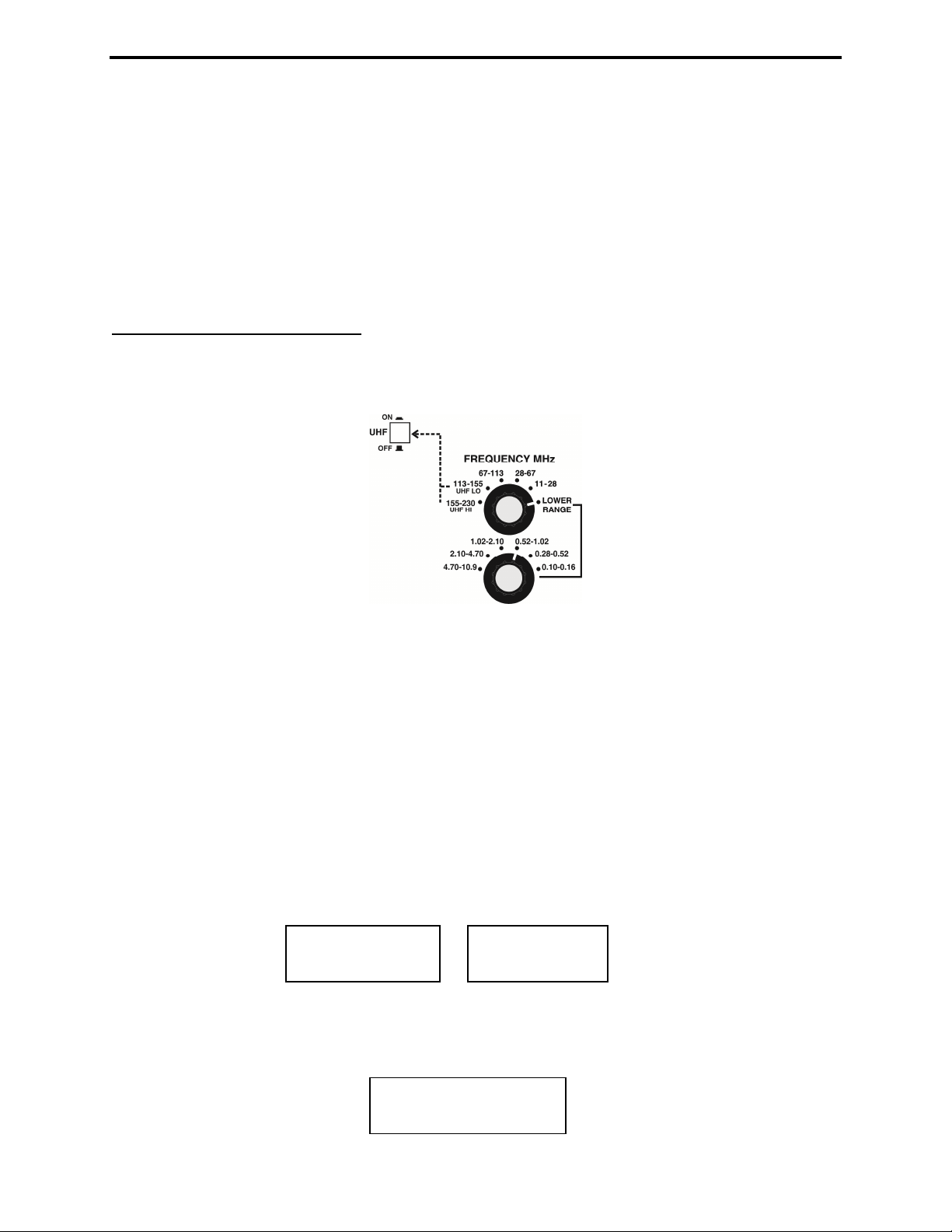
requency counter. Operating requency extends rom 0.10 to 230 MHz in nine overlapping bands with
extended SWR measurement rom 415 to 470 MHz.
1.1 Typical Use
The MFJ 269D may be used to adjust, test, or measure the following:
Antennas: ...................................SWR, impedance, reactance, resistance, resonant requency, and
bandwidth
Antenna tuners:..........................SWR, bandwidth, requency
Ampli iers:.................................Input and output matching networks, chokes, suppressors, traps, and
components
Coaxial transmission lines:........SWR, length, velocity actor, approximate Q and loss, resonant
requency, and impedance
Filters: ........................................SWR, attenuation, and requency range
Matching or tuning stubs: ..........SWR, approximate Q, resonant requency, bandwidth, impedance
Traps: .........................................Resonant requency and approximate Q
Tuned Circuits: ..........................Resonant requency and approximate Q
Small capacitors:........................Value and sel -resonant requency
RF chokes and inductors:...........Sel -resonant requency, series resonance, and value
Transmitters and oscillators:......Frequency
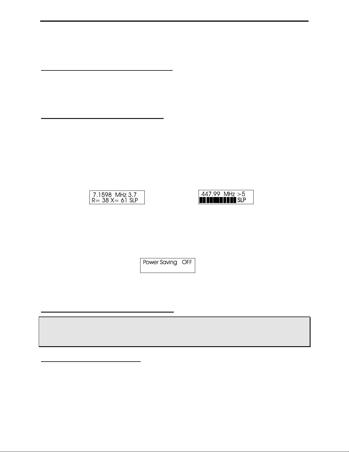
The MFJ 269D measures and directly displays the following:
Electrical length ( eet or deg) Impedance phase angle(degrees) Resonance (MHz)
Feedline Loss (dB) Inductance (µH) Return loss (dB)
Capacitance (pF) Reactance or X (ohms) Signal Frequency (MHz)
Impedance or Z magnitude (ohms) Resistance or R (ohms) SWR (Zo programmable)
The MFJ 269D is also useful as a non precision signal source. It provides a relatively pure
(harmonics better than -25 dBc) signal o approximately 3 Vpp (~20 mW) into a 50 ohm load. The
internal source impedance is 50 ohms. Although not "stabilized", it provides adequate stability or non-
critical applications such as alignment o broad-bandwidth ilters and circuits.

MFJ-269D Instruction Manual LF/HF/VHF/UHF SWR Analyz r
3
Note: For a more complete description o eatures and test methods, consult the table o contents to ind
the manual sections describing the particular measurement you wish to make.
1.2 Frequency Range
The unit's dual-range Frequency switches select the ollowing oscillator bands with a small overlap:
0.10-0.16 MHz 2.1-4.7 MHz 67-113 MHz
0.26-0.52 MHz 4.7-10.9 MHz 113-155 MHz/UHF LO*
0.52-1.02 MHz 10.9-28 MHz 155-230 MHz/UHF HI*
1.02-2.1 MHz 28-67 MHz
*A UHF pushbutton switch located above the LCD display activates 415-470 MHz SWR coverage. See
section 3.4 or VFO operating speci ics.
1.3 Accuracy No es
I measurement errors occur, they will likely be caused by one o the ollowing conditions:
1. Signal ingress rom external sources, usually rom a strong AM broadcast station.
2. Diode detector and A/D converter error.
3. Stray impedance errors contributed by connectors, cables, and adapters.
Broad band Voltage Detectors and External Interference: Laboratory grade network analyzers use
expensive high-selectivity gain-stabilized receivers to avoid o - requency inter erence and ensure
measurement accuracy. Building these sophisticated detectors into the MFJ-269D (or any small handheld
unit) would drive the price ar beyond the reach o most hobbyists. As an alternative, we use broadband
detectors that provide accurate measurements at a much lower cost. The only drawback is that broadband
detectors can be sensitive to power ul out-o -band signals. Most o the time, out-o -band inter erence isn't
an issue, but occasionally a particularly power ul signal may be picked up by the antenna under test and
routed into the analyzer bridge circuit where it con licts with the internally generated VFO signal. When
strong "signal ingress" such as this occurs, it may result in inaccurate readings.
The solution or out-o -band inter erence isn't simple. Increasing the analyzer's generator power would
help, but doing so causes the unit to draw signi icantly more power at the expense o reduced battery
operating time. Higher power may also cause on-air inter erence when testing antenna systems that
radiate e iciently or exhibit directivity gain. Using common low-pass or band-pass ilters similar to those
used in transceivers also wouldn't work because they behave like transmission lines o varying
impedance on di erent requencies. Using them would only introduce gross measurement inaccuracies.
MFJ 731: Fortunately, most analyzer inter erence problems occur on the lower requencies, with near-by
high power AM broadcast signals being the worst o ender. When testing physically large antenna arrays
such as 160-meter verticals, these power ul outside signals may couple very e iciently into the analyzer's
bridge circuit. Other strong local signals may "get in" as well. To correct the problem, we o er the MFJ-
731 tunable ilter, an accessory especially designed to attenuate o - requency signals. The MFJ-731
permits accurate impedance measurements between 1.8 and 30 MHz with virtually no impact on
measurement accuracy.
Detector Errors: At low voltages, detector diodes become non-linear. To address this issue, the MFJ-
269D uses special microwave zero-bias Schottky detectors with matched compensating diodes. Each unit

MFJ-269D Instruction Manual LF/HF/VHF/UHF SWR Analyz r
4
is individually compensated to provide the best detector linearity possible. Small errors may also occur
during A/D conversion due to practical limitations on bit resolution.
Connection lengths: Connection lengths both inside and outside the analyzer bridge can upset readings,
especially at higher requencies and when impedance is very high or very low. The MFJ-269D minimizes
internal problems by using sur ace mount low capacitance microwave components with nearly zero lead
length. It's important to remember that any external leads you add, even short leads, will modi y the
impedance o the load at radio requencies. To obtain highest accuracy, always use the shortest test
cables possible with the ewest connectors and adapters in the line.
Note: Some handheld analyzers display erroneous readings alling outside the reliable measurement
range, presenting that data numerically -- as i it were " actual". The MFJ-269D is designed to avoid such
errors by displaying an on-screen warning (Z > 1500) anytime data alls outside the unit's accurate
measurement range.
2.0 POWER SOURCES
This section describes power supply and battery selection.
READ THIS SECTION BEFORE CONNECTING THIS DEVICE TO ANY POWER SOURCE. IMPROPER
CONNECTIONS OR INCORRECT VOLTAGES MAY CAUSE DAMAGE TO THIS PRODUCT!
2.1 Ex ernal Power Supply
The MFJ-1312D satisfies all external voltage and current power source require ents and we highly
reco end using it with your MFJ-269D. External power require ents are as follows:
1. When the unit is ON, supply voltage must be over 11 volts but not exceeding 16 volts.
2. When in Sleep Mode or OFF (supply lightly loaded), voltage ust not exceed 18 volts.
3. The supply must be well filtered against hum and noise.
4. The MFJ 269D case (chassis ground) must be connected directly to the supply's negative terminal.
5. The supply ust not have a grounded positive lead (- center pin).
6. The "ideal" supply voltage is 13.8 volts dc.
7. When rechargeable batteries are used, 14 volts or higher is required for charger operation.
8. Current demand is 150 A (max) on HF and VHF, 250 A (max) on UHF.
WARNING: READ SECTION 2.2 THROUGH 2.4 (BATTERY INSTALLATION INSTRUCTIONS)
BEFORE INSTALLING BATTERIES.
The MFJ-269D has a recessed 2.1 mm power receptacle near the RF connectors. This receptacle is
labeled POWER 13.8 VDC. The outside conductor is negative, the center is positive. Inserting a
power plug in the POWER 13.8 VDC receptacle disables internal batteries as the analyzer's power
source. However, the internal batteries will still be trickle charged when the power supply plug is
inserted into the unit. Power plugs must be wired as shown below:
+
-
+
-
2.1 mm

MFJ-269D Instruction Manual LF/HF/VHF/UHF SWR Analyz r
5
WARNING: REVERSE POLARITY OR EXCESSIVE VOLTAGE CAN DAMAGE OR DESTROY THE
MFJ 269D. NEVER APPLY MORE THAN 18 VOLTS, NEVER USE AC OR POSITIVE
GROUND SUPPLIES! NEVER ADD OR REMOVE BATTERIES WITH AN EXTERNAL
POWER SUPPLY CONNECTED TO THIS UNIT, OR WITH THE POWER SWITCH ON.
2.2 In ernal Ba eries
When installing internal batteries, first check the position of a small black-plastic internal jumper plug
that controls charger operation. The jumper is located inside the unit at the top of the printed circuit
board near the area of the OFF-O switch and power connector. To access it, remove all eight screws
on the sides o the case and remove the back cover. The black plastic jumper its over two o three
adjacent pins (see detailed instructions below). The plug must be properly positioned or the type o cell
you plan to use (AA rechargeable or AA non-rechargeable).
2.3 Rechargeable Ba eries
I portant Note: When using rechargeable batteries, your external power source must deliver at least 14
volts. I supply voltage is too low, the charger can't unction and batteries will eventually discharge. I
batteries are depleted, charge with the analyzer power switch turned o -- it may take ten hours or more
to ully restore depleted cells.
I portant Warning: ever change batteries with the power switch "On" or with an external supply
plugged in -- permanent damage may result. Always remove batteries when shipping the analyzer or
storing it for an extended period (more than a month).
When using rechargeable batteries, the internal black plastic jumper must be set to the proper position.
Remove the analyzer cover and locate the jumper on the pc board (near the power jack). Con irm that it
is set correctly. I not, reposition as shown below:
Again, when the Charger Jumper is ON and a 13.8 to 18 volt source is applied, the charger will be
unctional. Typical charging current is 10-20 mA.
2.4 Using Conven ional “AA” Dry Cell Ba eries
When using non-reachable batteries, install only high quality alkaline cells in matched sets (same
manu acturer and date code). Conventional zinc-based cells have a shorter shel and service li e, and they
are also more prone to leakage. Also, to prevent leakage, remove weak alkaline batteries immediately.
WARNING: WHEN USING NON RECHARGEABLE BATTERIES, THE CHARGING SYSTEM MUST
BE DEFEATED! IF YOU FAIL TO FOLLOW THIS WARNING, THE BATTERIES WILL
LIKELY LEAK AND RUIN THE ANALYZER!
When using non-rechargeable batteries, set the internal jumper as shown below:

MFJ-269D Instruction Manual LF/HF/VHF/UHF SWR Analyz r
6
Never attempt to charge alkaline (or any other non-rechargeable cells) using the MFJ-269D's internal
charger circuit!
2.5 “Vol age Low” display warning
When the analyzer's supply or battery voltage drops below 11 volts, a blinking Voltage Low warning
will be displayed. Pressing Mode during a low-voltage warning will disable the on-screen alert and allow
you to continue operating. However, measurements may not be reliable when operating the analyzer with
insu icient supply voltage!
2.6 Sleep Mode “Power Saving”
Typical current drain or the MFJ-269D is around 150 mA or HF operation (250 mA or UHF). Battery
operating time is (by de ault) extended signi icantly through the use o Sleep Mode. Sleep mode reduces
current drain to less than 15 mA when it is engaged during periods o non-activity. Power-saving is a
de ault setting or the MFJ-269D unless you defeat it when you turn on the analyzer (instructions below).
Normally, the analyzer's processor looks or manual activation o the Mode switch or or any change in
Frequency greater than 50 kHz. I neither event occurs during any given three-minute interval, Sleep
mode automatically kicks in and places the analyzer in standby. A blinking SLP message in the display
screen lower-right corner indicates power-saving mode (see below):
To pull the unit out o SLP, momentarily press either the Mode or Gate button to resume operation.
To disable Sleep, irst turn the unit Off and then press and hold the Mode button when reapplying
power. Continue holding Mode until a ter the copyright message appears on the LCD screen, then
release. I the “Power Saving” mode has been is success ully disabled, the message shown below will
appear as soon as Mode is released.
Sleep Mode is a de ault unction and will reset automatically each time the analyzer is turned OFF. To
restore Sleep, simply turn the analyzer Off and then On again.
3.0 MAIN MENU AND DISPLAY
WARNING: NEVER APPLY RF OR ANY OTHER EXTERNAL VOLTAGE TO THE ANTENNA PORT.
THE MFJ 269D USES ZERO BIAS DETECTOR DIODES THAT MAY BE DAMAGED BY
EXTERNAL VOLTAGES. ALSO, READ SECTION 2.0 BEFORE APPLYING POWER.
INCORRECT SUPPLY VOLTAGE OR REVERSED POLARITY CAN CAUSE DAMAGE.
3.1 General Connec ions
The N- emale Antenna connector on top o the unit is the primary RF-measurement connection. It is
used or all unctions except requency counter measurements.
The Power connector (2.1 mm) is described in section 2.0. Please read the power-source section
care ully be ore attempting to operate the analyzer! Improper voltage application, the wrong battery
charger setting, or reversed polarity could permanently damage your unit.

MFJ-269D Instruction Manual LF/HF/VHF/UHF SWR Analyz r
7
The BNC Frequency Counter Input is or requency counter measurements only. See section 4.5 or
the counter's operating instructions.
3.2 Power-up Display
I portant Note: Be ore powering up the analyzer, check the status o the UHF switch located above the
LCD window on the le t. This switch must be in the "up" or in the Off position unless UHF operation is
intended.
Note: The ollowing is a description o the basic opening (or de ault) menu used by the MFJ-269D.
Your analyzer also has an advanced user section (5.0).
When applying Power, a sequence o message screens appear on the LCD display. The irst screen lists
the so tware version (Ver): Be sure to have this number handy when re erring technical questions about
your analyzer to MFJ Customer Service:
The second message shows the so tware copyright date:
The third message is a voltage check. It displays the operating voltage, indicating battery condition or
the voltage o your external power supply.
The ourth and inal screen is the irst "working display" (Complex Impedance). The two analog panel
meters also activate when the working display comes up.
3.3 Main Measuremen Modes (LF/HF/VHF, 0.10-230 MHz)
Momentarily pressing (or tapping) the Mode button a ter the irst working display appears allows you to
scroll through all ive basic measurement modes provided by the MFJ-269D. The opening mode is
Impedance R & X (resistance and reactance). As each new mode comes up, its title screen appears or
about two seconds, and then the companion data screen appears. Each o the ive Basic Modes are listed
below:
1. Impedance R&X: This is the analyzer's "de ault mode", and it is the unction most commonly used.
The top line o the data screen displays Frequency in MHz and SWR, while the bottom line shows
complex impedance where Rs equals the load's series resistive component and Xs shows the load's series
reactive component. In this unction, the analog SWR and Impedance Meters (Z) are also activeated.
2. Coax Loss: Pressing Mode once brings up the Coax Loss ollowed by the data screen. The top line
shows Frequency in MHz and the bottom line displays Coax Loss in dB.
3. Capacitance in pF: The third mode displays Frequency in MHZ on the top line, ollowed by Xc
(capacitive reactance) on the bottom line. The analog meter also shows reactance X.
MFJ Enterprises
(c) 2014
MFJ-269D
Ver 14.14

MFJ-269D Instruction Manual LF/HF/VHF/UHF SWR Analyz r
8
4. Inductance in µH: The ourth mode, Frequency appears on top and XL (inductive reactance) on the
bottom. Meter shows reactance (X).
5. Freq. Counter: The i th unction turns o the analyzer's internal oscillator and routes the input o the
counter to the BNC connector labeled Frequency Counter Input. In this mode, the top line o the LCD
display shows the measured Frequency in MHz and the counter's Gate Time in seconds.
I portant Note: Section-4 o this manual provides detailed instructions or using each o the ive basic
operating modes described above. To ensure accurate measurement and avoid the possibility o
inadvertent damage, please read through this section care ully be ore operating the analyzer!
3.4 Frequency Con rol
The MFJ-269D tunable RF-oscillator covers an exceptionally wide requency span, using two rotary
band switches or LF/HF/VHF coverage (0.10-230 MHz) -- plus an additional pushbutton switch to
activate UHF coverage (415-470 MHz) .
1. LF, HF and VHF Operation: The Lower Range rotary switch selects our LF and HF bands (0.10-
11.0 MHz). The Upper Range switch selects 5 HF and VHF bands or 11-230 MHz coverage. Note that
the Upper Range switch must be set fully clockwise to the Lower Range position or the lower-range
band selector to unction. The variable Tune control (VFO capacitor) provides a small overlap at each
band edge to ensure gap- ree tuning across the spectrum.
2. UHF Operation: UHF coverage is broken into two bands. To measure UHF SWR (415-490 MHz),
irst press in the UHF switch located just above the LCD display. Then, or 415 470 MHz coverage, set
the upper Frequency MHz switch to the 113 155 MHz band (UHF LO). For 470 490 MHz coverage,
set the upper Frequency MHz switch to 155 230 MHz. (UHF HI).
It is normal or the VFO's Tune range to exceed the analyzer's usable UHF measurement range. I the
VFO requency is out o range in UHF Mode, one o the error messages shown below will instruct you to
increase or decrease requency to bring it back in range:
Adjust Tune clockwise to increase frequency and counterclockwise to decrease frequency. When in
range, the operating Frequency will appear on the top line o the LCD display -- along with the SWR
reading. The bottom display line becomes an analog SWR bar graph (see below).
445.75 MHz 1.3
I CREASE
FREQUE CY
DECREASE
FREQUE CY

MFJ-269D Instruction Manual LF/HF/VHF/UHF SWR Analyz r
9
Remember to set the top Frequency MHz selector ully counterclockwise (155 230) when setting up or
UHF HI (470 490MHz) or set to the second to last switch position (113 155) when setting up or UHF
LO (415 470 MHz) measurements. The analyzer converts the analyzer's VHF oscillator up to the UHF
band or those measurements.
4.0 MAIN (OR OPENING) MODE
IMPORTANT WARNING: Never apply RF or DC voltages to the Antenna port of this unit. It uses
zero bias detector diodes that are easily da aged by any external voltages over a few volts. Also,
confir the power supply voltage and polarity are correct, as described in Section-2.0.
A basic understanding o antenna theory and transmission line behavior will prove help ul or making the
best use o the data provided by your MFJ-259C. The ARRL Handbook and ARRL Antenna Book
provide concise peer-reviewed explanations that should su ice or most applications. When it comes to
the iner points o antenna design, there is (un ortunately) a air amount o misin ormation circulating on
the web and over the airwaves. When it comes to RF networks and antenna systems, there's no black
magic. Stick with the undamentals as presented by credible pro essional sources.
4.1 General Connec ions
When conducting SWR and Impedance measurements, ollow these practical guidelines:
1. Connectors: I connector transitions (RF adapters) are needed, use only high-quality parts and check
them or wear, oxidation, dirt, and tight pin contact be ore proceeding.
2. Lead Length: Make all connection electrically secure and keep all leads as short as possible. This
precaution is especially important when measuring electrical components that are not part o a 50-ohm
coaxial system.
3. Coaxial Cable: Always use good quality 50-ohm cable and connectors when making SWR
measurements. Contaminated, mismatched, or damaged cable will introduce signi icant error.
4. Calibration Plane: When making Complex Impedance measurements, (R+X) or (Z), remember that
any length of trans ission line you install between the load and the analyzer will displace the load
fro the analyzer's calibration plane.
For simple handheld analyzers like the MFJ-269D, the calibration plane is always located at the
analyzer's RF connector. This is the point where Zo=50 Ohms and Phase shi t = 0 degrees. It is the only
test point where the analyzer will be calibrated for complex impedance measurements. Displacing the
load away rom the analyzer's calibration plane through random lengths o coax should have little or no
impact on SWR readings, but will introduce signi icant error through phase shi t and trans ormer action
to invalidate virtually any complex impedance measurement you might make.
When easuring Co plex I pedance, always connect the MFJ-269D as close (electrically) as
possible to the DUT (device under test)!
4.2 An enna SWR and Impedance
Use the N-Female Antenna connector located on top o the MFJ-269D or all RF measurements (except
those using the Frequency Counter mode). Follow the procedure outlined below or measuring SWR:

MFJ-269D Instruction Manual LF/HF/VHF/UHF SWR Analyz r
10
1. I your antenna doesn't have a dc-grounded eed system, momentarily short the cable's center
conductor to the shield immediately be ore connecting up to the analyzer. This simple procedure will
discharge any static buildup on the antenna and prevent damage to the analyzer's sensitive detector
diodes.
2. Connect the antenna lead to the analyzer's N-Female Antenna connector.
3. Set the VFO's two Frequency selector band switches or the appropriate range.
4. Turn on the Power switch while watching the display. Battery voltage should read OK (11-16 volts).
5. Following the boot screens, the de ault mode will come up with the working screen or Frequency,
SWR, Resistance (R), and Reactance (X). The SWR and Impedance analog meters will also
become active.
6. Adjust Tune (the VFO capacitor) as needed to ind your desired test requency -- or tune until you
obtain a minimum SWR reading.
Note that the MFJ-269D also has Advanced antenna-measurement modes that are described in detail in
Section-5.0. However, unless you have a strong working knowledge o RF systems, you may ind these
added modes o limited value. Most represent more technically sophisticated ways o expressing the
same data o ered by the basic modes.
An enna hin s:
1. Measuring Antenna Impedance: For complex impedance measurements, always install the analyzer
as close as possible to the element's eedpoint (within or 1-2 degrees o phase shi t). Alternatively, you
may use a precisely cut 1/2-wavelength o cable displace the calibration plane by a controlled amount
(360-degree phase rotation).
2. Electrical Half Wavelengths of Cable: Installing a hal -wavelength o cable between the load and
the analyzer will rotate phase a ull 360 degrees so that no apparent trans ormation takes place in the line.
However, the response will only be transparent on one discrete frequency. Even a small requency
change will begin to skew your impedance readings and may even shi t the antenna's resonant requency
as the cable begins to introduce its own reactance into the system. Phase errors compound with multiple
hal -wavelengths, so limit cable length to one or two phase rotations at most!
3. SWR, Resonance, and Impedance: It's always preferable to measure SWR rather than resonance or
impedance magnitude (Z) as the standard for adjusting your antenna.
By de inition, minimum SWR (1:1) and maximum power trans er occur when the source, transmission
line, and load impedance are all o equal value (conjugate match).
Resonance occurs when reactance fully cancels at the antenna's eedpoint, causing the load to become
purely resistive (Xc + XL = 0).
Although Minimum SWR and Resonance o ten coincide, they are not directly correlated and rarely will
occur on exactly the same requency. I your antenna doesn't happen to present a 50-ohm load at
resonance, there will still be resistive mismatch (and SWR) in the system. In act, slightly lower SWR
may actually occur on some other requency. By the same token, i you adjust your antenna or an
Impedance reading o 50 ohms, it may have a substantial reactive component ( or example R = 46, X =
17) that would elevate SWR and shi t the minimum-SWR point to a di erent requency.

MFJ-269D Instruction Manual LF/HF/VHF/UHF SWR Analyz r
11
SWR is always your best predictor of antenna perfor ance.
4. Tuning and Matching: Unlike simple wire dipoles, many antennas such as Yagis and verticals are
adjustable or both resonant frequency and impedance match. Begin by setting these antennas or the
element length prescribed in the instruction sheet. Then, adjust the matching network or minimum SWR.
The two adjustments are separate, but o ten interact. Be prepared to alternately readjust both the element
length and the matching network to achieve minimum SWR on your requency o interest.
5. Adding and Removing Feedline: You should be able to add or remove lengths o eedline (or to
measure SWR at any point along your eedline) without observing a signi icant change in SWR. It is
normal to see SWR drop slightly as cable is added, or see it increase slightly as cable is removed because
o a change in resistive loss. However, (a.) i your SWR measurements change a lot with relatively small
changes in cable length, or (b.) SWR changes as the cable is moved around, or (c.) SWR changes when
the coax shield is grounded at some point part way between the antenna and the radio, look or a eed
problem! Here are some possibilities to check:
6. Common Mode Current: Your coax may be carrying Common-Mode Current on its outer shield and
radiating RF. To eliminate this problem, install a Guanella current balun at the eedpoint. It will isolate
the outer coax shield rom the radiating portion o the antenna, stabilize your SWR, reduce receiver
noise, and suppress "RF in the shack". Installing a balun is good engineering practice and always worth
doing!
7. Defective Cable: Your coax may not really be 50 ohms. Kinks, water ingress, oxidation, corrosion,
bad connectors, improper manu acturing, or even mislabeling may be the cause. Check SWR with a
dummy load installed at the ar end o the cable. I the SWR is elevated or the Impedance (Z) luctuates
very much as you tune the analyzer's VFO, suspect a de ective cable.
8. Excessive Transmission Line Loss: Your cable may exhibit unusually high loss because o damage
or contamination. Or, it may simply have too much normal attenuation or the requency range where
you're using it (especially true at VHF and UHF). To measure loss, unterminate the cable at its ar end
and use the analyzer's Coax Loss mode to check it.
9. Reactance Sign: The MFJ-269D measures the antenna's reactance (X) and mathematically converts it
to a value. Un ortunately, the analyzer's processor can't determine i the reactance it measures is actually
inductive (+jX) or capacitive ( jX). However, you can o ten determine the reactance sign by installing a
small-value o capacitance across the antenna eedpoint. I the reactance increases, it is likely capacitive
because the two are the same sign and add. I the reactance reading decreases, it is likely inductive
because the reactance signs are opposite and subract. Note that the reactance o the added capacitor must
be quite small at the test requency to avoid potential ambiguity.
4.3 Coax Loss (Func ion-2)
Bring up the analyzer's coax loss mode by stepping the Mode switch to the Coax Loss identi ication
screen. The top line o the working screen displays Frequency in MHz and the lower line shows Coax
Loss in dB. Note that the Impedance meter is disabled in this mode. Coax Loss was designed to measure
losses in 50-ohm cables, but also e ectively measures di erential-mode loss in many types o 50-ohm
transmission-line trans ormers, choke baluns, and 50 ohm attenuator pads.
CAUTION: Only measure transformers or attenuators and coaxial cables that are 50-ohm devices. Also,
when making your measurement, confirm that the opposite end of the DUT (device under test) has an
open circuit, short circuit, or a purely reactive termination. Any resistive component added at the far-end
termination point will make attenuation (loss) appear worse than it actually is.
To measure loss:

MFJ-269D Instruction Manual LF/HF/VHF/UHF SWR Analyz r
12
1. Connect the 50-ohm cable, attenuator, transmission line type balun, or trans ormer under test to the
Antenna connector. Con irm the distant end o the DUT isn't terminated by a resistance.
2. Turn the analyzer On and toggle the Mode switch once to the Coax Loss screen.
3. Tune the analyzer's VFO (Tune) to the requency where you wish to measure loss. The loss in dB will
be displayed or any speci ic requency you select between 0.53 and 230 MHz.
4.4 Capaci ance (Func ion-3)
Access the capacitance mode by stepping to the Capacitance screen using the Mode switch. The top line
o the working display shows the Frequency in MHz and the Capacitive Reactance (Xc) o the DUT at
that speci ic requency. The lower line displays the computed Capacitance in pF. Normally, the
measurement range is rom a ew pF to a ew thousand pF.
I portant Note: Capacitance measurements tend to become inaccurate below 7 ohms and above 650
ohms. If reactance falls into the inaccuracy range, C(X<7), C(X=0), or C(Z>650) will be displayed on
the screen as error messages. The MFJ-269D will not display "data" when the measurement accuracy is
questionable (see examples below):
Reactance Sign: The MFJ-269D measures the DUT's reactance (X) and mathematically converts it to a
capacitance value (Xc). However, the analyzer's processor can't determine i the reactance it measures is
actually capacitive or inductive. You can usually con irm the sign by simply adjusting the VFO. I tuning
down in requency causes reactance to increase, the load is likely capacitive (-jX) because the reactance
o a capacitor normally increases with a decrease in requency.
To measure a capacitor:
1. Turn on the analyzer and toggle the Mode switch twice to bring up the Capacitance identi ication
screen.
2. Connect the capacitor across the Antenna connector with the shortest leads possible, or include the
lead length normally used in the actual circuit to include stray lead inductance in your measurement.
3. Adjust the VFO (Tune) to your requency o interest. I a range warning comes up, ind the closest
requency where no warning appears. Warnings are C(Z>650), C(X<7), and C(X=0) -- and the C(X=0)
warning indicates the capacitor appears as a near-per ect short.
When measuring a capacitor, it's displayed value in pF will typically change with the test requency. This
change occurs because stray inductance inside the capacitor and in the wires leading to the analyzer

MFJ-269D Instruction Manual LF/HF/VHF/UHF SWR Analyz r
13
calibration plane are in series with it. The actual value (in pF) or most capacitors does increase with
requency and may reach infinity when the capacitive element and its stray inductance become series-
resonant. This requency is called the device's Series Resonant Frequency (where X=0). Bypass
capacitors are sometimes intentionally operated at or near this requency, but or most applications, the
requencies will be ar below it. In addition to the display, the analyzer's Impedance meter displays the
reactance (X in ohms) o the capacitor.
4.5 Induc ance (Func ion-4)
Access the Inductance mode by stepping the Mode switch to the Inductance identi ication screen. The
top line o the working display shows the Frequency in MHz and the Inductive Reactance (XL) o the
DUT at that particular requency. The lower line shows the Inductance in uH. Inductance is calculated
using the measured Reactance (XL) and the VFO requency.
I portant Note: Measurements become inaccurate below 7 ohms or above 650 ohms. If component
reactance falls into an inaccurate range, the error messages L(X<7), L(X=0) or L(Z>650) will be
displayed.
Reactance Sign: The MFJ-269D measures reactance (X) and mathematically converts it to an inductance
value XL, but the processor can't actually determine i the reactance it measures is inductive or
capacitive. You can usually con irm the sign by adjusting the VFO. I tuning down in frequency
decreases reactance, the reactance is likely inductive (+jX) because inductors normally exhibit decreased
reactance with a decrease in requency.
To measure an Inductor:
1. Turn the analyzer on and step the Mode switch three times to bring up the Inductance identi ication
screen.
2. Connect the inductor (DUT) across the Antenna connector using the shortest leads possible, or with
the lead length normally used in your working circuit to include stray inductance in the measurement.
3. Adjust the VFO (Tune) to your requency o interest. I an error sign comes up, choose the closest
requency where no warning appears. The L(X=0) warning indicates the inductor looks like a near
per ect short to the analyzer's bridge and the requency is too low (or the inductor too small) to measure.
The digital display and the analog Impedance meter both present the DUT's reactance (X) in ohms.
When measuring an inductor, its displayed value will sometimes change with the test requency. This
happens because o stray capacitance between coil windings and in the leads going to the Antenna
connector. At RF, the value o an inductor (in uH) may appear substantially di erent rom its "rated"
value that was determined at a lower requency. With increasing frequency, measured inductance usually
increases and, at some high frequency, the coil may become self-resonant and appear as an open circuit
(or a trap) with infinite reactance. At some very low requency, it may look like a short.
Inductance
in uH

MFJ-269D Instruction Manual LF/HF/VHF/UHF SWR Analyz r
14
4.6 Frequency Coun er (Func ion-5)
The Frequency Counter mode is the inal Main Mode unction. To access the counter rom the opening
menu, press Mode our times (or i already in the Main menu, step through it until the Freq. Counter
screen appears.
I portant Note: ever apply dc or more than 5 volts peak-to-peak to the BNC Frequency Counter
Input jack. In this mode, the Gate button controls the counter's time base window. As a general rule the
longer the window, the more accurate the requency count. The accuracy o this counter is typically
better than 0.05 %. Note that sensitivity o the counter tends to decrease with higher requency signals.
5.0 ADVANCED OPERA ION
5.1 Forward
The advanced mode provides several special unctions. Some unctions are very use ul, such as distance
to ault (HF/VHF) or transmission line length in degrees.
Measure ent Notes: The Advanced menus present data in more "technical" or potentially un amiliar
terms. Advanced- 1 includes impedance descriptions such as Magnitude and Phase of Load Impedance,
Series and Parallel Equivalent Impedance, Reflection Coefficient, and Resonance. Most o these terms
are use ul in special applications, such as in adjusting matching stubs, but may not be use ul or making
simple antenna adjustments. The advanced menus also contain uncommon terms describing basic SWR,
such as Return Loss and Match Efficiency. These, also, represent engineering terms that may prove
misleading because "label" may not imply what is actually happening in the RF system. I a concept or
term is un amiliar to you, it's probably wiser to avoid using it to in luence your decision-making until you
understand its ull technical meaning.
Infor ation Sources: A basic understanding o transmission line and antenna behavior and terminology
is very important in understanding Advanced Mode in ormation provided by the MFJ-269D. Many
explanations are available in the ARRL Handbooks, and they probably su ice or most amateur
applications. Avoid unedited or sel -edited amateur handbooks or articles, or at least con irm their
accuracy by checking the in ormation against reliable pro essional sources. For complex questions or
critical in ormation, we recommend using textbooks written, reviewed, and edited by pro essional
engineers.
Accuracy Notes: The MFJ-269D contains a 50-ohm bridge, with voltage detectors across each bridge
leg. A twelve-bit microcontroller measures these voltages and, by applying the proper ormulas, displays
use ul in ormation. The basic calculations are resistance, reactance, SWR, and complex impedance. In
some modes, the system cross checks itsel and displays a weighted average o the most accurate
measurement methods, or searches or certain impedance conditions. System resolution is limited mostly
by diode linearity, calibration stability, and external noise or signals.
While we have attempted to make this unit as accurate as possible, most ormulas contain squares and
other complex unctions. A certain amount o error is unavoidable, especially at high or low impedance
values and especially at higher VHF or UHF requencies.
5.2 Accessing Advanced Modes
The advanced mode is reached by pressing and holding the Gate and Mode buttons at the same time or
several seconds. A ter a delay o a ew seconds, a series o Advanced messages numbered 1 through 3
appear. When you see the mode you want, quickly release the buttons. I you hold the buttons long
enough, the display will eventually loop back through the MAIN menu and repeat the cycle.

MFJ-269D Instruction Manual LF/HF/VHF/UHF SWR Analyz r
15
*LF/ HF/VHF operation: The ollowing modes are available rom each o these Advanced menus:
Advanced 1 Magnitude and phase o load impedance
(Section 5.4.1) Series and Parallel Equivalent Impedances
Return Loss and Re lection coe icient
Resonance
Match E iciency
Advanced 2 Velocity Factor setup
(Section 5.5) Distance to Fault measurement
Line length in degrees calculation
Advanced 3 Characteristic Impedance setup
(Section 5.6) Normalized SWR impedance (display only)
Coax loss
* UHF operation: The ollowing modes are available rom each o these Advanced menus:
Advanced 1 Return Loss and Re lection coe icient
(Section 5.4.2) Match E iciency
Advanced 2 Velocity Factor setup
(Section 5.5) Line length in degrees calculation
5.3 General Connec ions
The Antenna connector (Type “N” emale) on the top o the MFJ-269D provides the RF measurement
output connection. This port is used to measure SWR or per orm other RF impedance measurements,
with the exception o the Frequency Counter mode.
The Antenna connector supplies about +7 dBm output into 50 ohms (~ .5 volts RMS), and appears like a
50 ohm source resistance (open circuit voltage ~1 volt RMS). Harmonics are at least 25 dB down over
the operating range o the MFJ-269D. While the VFO is not stabilized, it is use ul as a crude signal
source.
The Antenna connector is not dc isolated rom the load, external voltages will couple directly into
internal detectors.
When testing antennas, especially those that do not have a dc path to ground, discharge any static
electricity that may have built up on the antenna be ore connecting the MFJ-269D. Because the Antenna
connector is not dc isolated static electricity can damage the internal detectors.
WARNING: NEVER APPLY EXTERNAL VOLTAGES OR RF SIGNALS TO THE ANTENNA
CONNECTOR. ALSO, PROTECT THIS PORT FROM ESD.
Use proper RF connections. Keep leads as short as possible when measuring components or non-matched
systems. Interconnecting transmission lines or wires can modi y readings, including impedance and
SWR. Use properly constructed coaxial cables o known quality matched to the analyzer impedance to
avoid introducing SWR errors.

MFJ-269D Instruction Manual LF/HF/VHF/UHF SWR Analyz r
16
5.4 Advanced -1 Modes
5.4.1 Advanced 1 (LF/HF/VHF)
Advanced 1 Mode measures impedance and SWR unctions. To enter Advanced 1, press and hold down
the Mode and Gate buttons simultaneously or approximately two seconds.
Advanced 1
There are six display unctions available within this mode (see list below):
Magnitude and phase o load impedance (5.4.1.1)
Series Equivalent impedance (5.4.1.2)
Parallel Equivalent impedance (5.4.1.3)
Return loss and Re lection coe icient (5.4.1.4)
Resonance (5.4.1.5)
Match e iciency (5.4.1.6)
To return to the Main (or Basic) menu, press and hold the Mode and Gate buttons to step through the
Advanced-2 and Advanced-3 screens.
5.4.1.1 Magni ude and Phase of Load Impedance
Magnitude and Phase of Impedance is the irst selection in the Advanced 1 menu, and it comes up
automatically upon entering Advanced 1 Mode. I already using one o the Advanced-1 unctions, you
may "step" or "scroll" to the Magnitude and Phase of Impedance mode by holding down Mode and Gate
switches. The opening display irst indicates:
and then lashes to:
In this mode, the LCD displays Frequency, Impedance Magnitude (Z) (in ohms), and Phase Angle of the
Impedance (θ). The meters indicate 50-ohm normalized SWR and the load Impedance (Z). The
maximum impedance limit is set at 1500 ohms. Exceeding this limit results in an impedance display o
(Z>1500).
Note: Stray connector capacitance will be lower than 1500 ohms at requencies higher than 30 MHz, and
lower as adapters and leads are added to the Antenna port. This small stray capacitance will not a ect
high requency measurements, and produces only minor errors in measurement o impedances under a
ew hundred ohms at VHF.
Phase angle of Impedance is another way o expressing R and X. Instead o providing R and X as
separate numerical quantities, it presents a vector-type description o measured impedance. Impedance
(Z) is still described as the length (magnitude) o a line representing the complex impedance (this is the
same Z as given in other unctions). Besides Z, an angle between zero and 90 degrees is shown. This
angle represents the phase di erence between current and voltage at the terminals o the analyzer.

MFJ-269D Instruction Manual LF/HF/VHF/UHF SWR Analyz r
17
When a reactance is present, voltage and current are no longer in phase (or exactly out-o -phase) and so
the phase angle increases rom 0 degrees to a maximum angle o 90 degrees. The angle becomes 90
degrees when the load is a pure reactance, and zero degrees when the load is a pure resistance.
This analyzer will determine the angle in degrees, but it will not describe the load reactance speci ically
as either capacitive or inductive. It is a simple matter to determine the direction by adding a small
amount o reactance in series with the load and watching the angle change. I the angle decreases, the
load reactance is opposite to the sign or type o test reactance. I the angle increases, the load reactance
is the same sign as the added reactance.
5.4.1.2 Series Equivalen Impedance
The Advanced 1 display sub-mode is reached by pressing the Gate button once while in the Magnitude
and Phase of Load Impedance mode. This mode displays the series-equivalent impedance o the load.
It is the most common orm used to describe antenna system impedance. In this mode, the load
impedance is described as a resistance in series with a reactance. In order to cancel the reactance
without changing the resistance, a reactance o the opposite type and value must be connected in series
with the load at the point o measurement.
The digital display shows SWR, resistive part o load impedance (Rs), and reactive part o load
impedance (Xs). The Impedance meter displays the Z in ohms while the SWR meter displays 50-ohm
re erenced SWR.
Series Equivalent I pedance display examples:
7.1598 MHz 3.2
Rs=50 Xs= 62
14.095 MHz >31
Rs(Z>1500)
s
W
R
s
W
R
In the le t-hand display (above), resistance would remain at 50 ohms, reactance would go to zero, and
SWR would become 1:1 i an opposite-sign reactance o 62 ohms was connected in series with the
eedline at the point where the measurement is made. The screen on the right illustrates a reactance value
out o measurement range.
Note: Every series impedance has a parallel equivalent counterpart. A Series Impedance o Rs=50,
Xs=62 is equal to the Parallel Equivalent Impedance o Rp=126, Xp=102 ohms. You can make the
conversion in this mode by pressing the Gate button (see section 5.4.1.3 below).
5.4.1.3 Parallel Equivalen Impedance
Pressing the Gate button twice rom the Magnitude and Phase of Load Impedance mode toggles the
analyzer into a parallel equivalent impedance sub-mode.
Parallel equivalent display examples:
7.1598 MHz 3.2
Rs=126 Xs=102
14.095 MHz >31
Rs(Z>1500)
s
W
R
s
W
R
In the le t hand display, the Equivalent Parallel Resistance is Rs=126 ohms. That resistance appears to
be in parallel with Xs=102 ohms. I we parallel connect an opposite-sign reactance o 102 ohms at the
measurement point, the parallel equivalent reactance is canceled, leaving only the Rs=126-ohm (pure)
resistance.
This is a power ul tool used in matching antennas, and the MFJ-269D places it at your ingertips. By
checking a load or both Rp and Rs, you can see i either one is close to the desired resistance. I one
resistance value is close to the desired value, adding only one component will match the load by
canceling reactance.

MFJ-269D Instruction Manual LF/HF/VHF/UHF SWR Analyz r
18
5.4.1.4 Re urn Loss and Reflec ion Coefficien
To access Return Loss and Reflection Coefficient, enter Advanced-1 and press the Mode button once.
You may also access it rom any other mode in Advance-1 by stepping through the menu using the Mode
button. The entry screen is shown below:
The Return Loss and Reflection Coeff mode measures and displays Return Loss in dB along with the
Voltage Reflection Coefficient. These measurements are alternative terms that describe SWR. In this
mode, the analog meters indicate SWR (normalized to 50 Ohms) and Impedance (Z). To use this mode,
connect the DUT to Antenna and adjust the VFO or Frequency. Sample display screens are shown
below:
5.4.1.5 Resonance
To access Resonance Mode, enter Advanced-1 and then press Mode twice. I already in Advanced-1,
scroll to it using the Mode switch. The entry screen is shown below:
Resonance Mode draws attention to reactance, displaying it on the Impedance meter as an analog tuning
aid or identi ying resonance. In this mode, the MFJ-269D measures and displays Frequency, SWR,
Resistance (Rs), and Reactance (Xs). When reactance equals zero in a system that has selectivity, the
system is said to be resonant.
Note: Because o transmission line e ects, zero-reactance (or resonance) can occur on requencies
where the antenna is not actually resonant. Conversely, an antenna may appear to contain reactance even
at its true resonant requency when it is measured through a eedline. A less-than-per ectly matched
antenna and eedline, when used with a eedline that is not an exact multiple o 1/4 wavelength (0, 1/4,
1/2, 3/4, etc.), will have reactance added by the eedline. Reactance added by a non-quarter wave
multiple mismatched eedline may coincidentally cancel a non-resonant antenna’s reactance, making the
system resonant.
The SWR o the system, i the eedline is a true 50-ohm eedline (or any impedance eedline that matches
the normalized (Zo) impedance setting o the instrument) with minimal loss and ree rom common mode
currents, will not change as the eedline length is changed. This is true even i the resonant requency or
reactance changes.
Table of contents
Other MFJ Measuring Instrument manuals