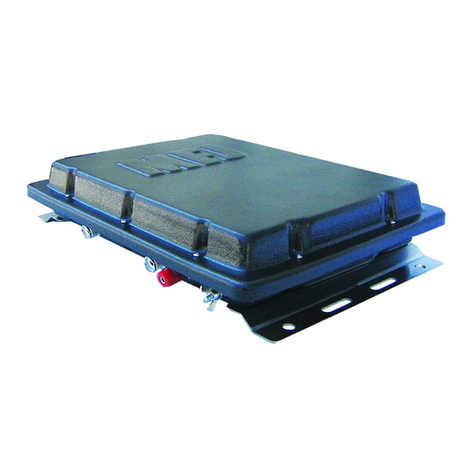
MFJ Plug&Play Intellituner -939 User manual


MFJ-939 Plug&Play IntelliTuner Automatic Antenna Tuner Instruction Manual
2006-2015 MFJ Enterprises, Inc.
ii
Contents
The Basics .....................................................................................................................................................................1
Introduction...........................................................................................................................................................1
Models ..................................................................................................................................................................2
Features .................................................................................................................................................................2
Speci ications ........................................................................................................................................................2
Fast Start........................................................................................................................................................................3
Front Panel.....................................................................................................................................................................4
Automatic/Semi-Automatic Tuning Mode............................................................................................................5
Back Panel .....................................................................................................................................................................6
Installation .....................................................................................................................................................................7
General Tuner Setup and Cabling .........................................................................................................................8
Modi ication to Change Radio Model ..........................................................................................................8
Operation .......................................................................................................................................................................9
MFJ-939I Icom ..................................................................................................................................................9
Operation......................................................................................................................................................9
Icom Radio Inter ace............................................................................................................................9
Connections.................................................................................................................................9
MFJ-939K Kenwood........................................................................................................................................11
Operation....................................................................................................................................................11
Kenwood Radio Inter ace ..................................................................................................................11
Connections...............................................................................................................................11
MFJ-939Y Yaesu .............................................................................................................................................13
Operation or FT-100 .................................................................................................................................13
Operation or FT-450 .................................................................................................................................13
Operation or FT-857 or FT-897 ................................................................................................................13
Operation or FT-950 .................................................................................................................................14
Yaesu Radio Inter ace MFJ-5114Y ...................................................................................................14
Connections...............................................................................................................................14
Connections or the FT-100 ......................................................................................................15
Connections or FT-450 ............................................................................................................15
Connections or FT-857 or FT-897 ...........................................................................................15
Connections or FT-950 ............................................................................................................16
MFJ-939Y3 FT-1000MP FT-2000 FT-9000.....................................................................................................18
Operation or FT-1000MP series o radios.................................................................................................18
Operation or FT-2000 series o radios ......................................................................................................18
Operation or FTDX-9000 series o radios.................................................................................................18
Yaesu Radio Inter ace MFJ-5114Y3 .................................................................................................18
Connections...............................................................................................................................18
Connections or FT-1000MP series o radios............................................................................19
Connections or FT-2000 series o radios .................................................................................19
Connections or FTDX-9000 series o radios............................................................................20
MFJ-939Y4 FT-2000 ........................................................................................................................................21
Operation or FT-2000 series o radios ......................................................................................................21
Yaesu Radio Inter ace MFJ-5114Y4 .................................................................................................21
Connections or FT-2000 series o radios .................................................................................21
Modi ication For Use With Alinco .....................................................................................................................22
Alinco Radio Inter ace .......................................................................................................................22
Connections...............................................................................................................................22
Operation...................................................................................................................................22
Miscellaneous ..............................................................................................................................................................23
ANTENNA MEMORY ......................................................................................................................................23
INTELLITUNETM ALGORITHM ......................................................................................................................23
LC Limits ............................................................................................................................................................23
MORSE CODE AND BEEPS ............................................................................................................................24
TRANSCEIVER FOLDBACK...........................................................................................................................24

MFJ-939 Plug&Play IntelliTuner Automatic Antenna Tuner Instruction Manual
2006-2015 MFJ Enterprises, Inc. iii
GROUNDING HINTS........................................................................................................................................25
ANTENNA SYSTEM HINTS............................................................................................................................25
Location......................................................................................................................................................25
Matching Problems.....................................................................................................................................25
Appendices ..................................................................................................................................................................27
Resetting the Tuner .............................................................................................................................................27
Factory De aults .........................................................................................................................................27
Delete Entire Antenna Memory..................................................................................................................28
Delete Antenna Memory Bank ...................................................................................................................28
Total Reset..................................................................................................................................................28
Sel Test ..............................................................................................................................................................28
Power-Down Circuit Test ...................................................................................................................................29
Relay Test ...........................................................................................................................................................30
Frequency Counter Calibration ...........................................................................................................................30
SWR Bridge Calibration .....................................................................................................................................31
Jumper Settings...................................................................................................................................................32
IN CASE OF DIFFICULTY...............................................................................................................................33
TECHNICAL ASSISTANCE.............................................................................................................................33
LIST OF ACCESSORIES ..................................................................................................................................33
FULL 12-MONTH WARRANTY ..............................................................................................................................35
Figures
Figure 1 General Setup ...............................................................................................................................................3
Figure 2 MFJ-939 Front Panel....................................................................................................................................4
Figure 3 Button Action ...............................................................................................................................................5
Figure 4 MFJ-939 Back Panel. ...................................................................................................................................6
Figure 6 General Setup ...............................................................................................................................................8
Figure 7 Icom Inter ace Cable. ...................................................................................................................................9
Figure 8 Kenwood Inter ace Cable...........................................................................................................................12
Figure 9 Yaesu Inter ace Cable (FT-100/-450/-857/-897/-950). ..............................................................................14
Figure 10 Yaesu Inter ace Cable (1000MP/2000/9000 series)...................................................................................19
Figure 11 Yaesu Inter ace Cable (FT-2000 series).....................................................................................................21
Figure 12 Alinco Inter ace Cable. ..............................................................................................................................22
Figure 13 Power-On Operations. ................................................................................................................................27
Figure 14 Block Diagram ...........................................................................................................................................34
Tables
Table 1 Icom...............................................................................................................................................................9
Table 2 Kenwood......................................................................................................................................................11
Table 3 Yaesu ...........................................................................................................................................................14
Table 4 Y3 Inter ace .................................................................................................................................................18
Table 5 Y4 Inter ace .................................................................................................................................................21
Table 6 Alinco ..........................................................................................................................................................22
Table 7 Memory Resolution .....................................................................................................................................23
Table 8 Tuner Beeps.................................................................................................................................................24
Table 9 Failure Messages. ........................................................................................................................................29
Table 10 Jumper JP1 Setting ......................................................................................................................................32
Table 11 Jumper JP2 Setting ......................................................................................................................................32
Table 12 Jumper JP4 Setting ......................................................................................................................................32

MFJ-939 Plug&Play IntelliTuner Automatic Antenna Tuner Instruction Manual
2006-2015 MFJ Enterprises, Inc.
iv
Notes:

MFJ-939 Plug&Play IntelliTuner Automatic Antenna Tuner Instruction Manual
2006-2015 MFJ Enterprises, Inc. 1
THE BASICS
Introduction
The MFJ-939 Plug&Play IntellitunerTM a simple to install and convenient antenna tuner for use with Icom,
Alinco, Kenwood, or aesu radios. The MFJ-939 comes complete with interface cable and programmed
for your particular radio.
The MFJ-939 Plug&Play IntelliTunerTM lets you rapidly tune any unbalanced or single-wire antenna
automatically. MFJ's exclusive InstantRecallTM, IntelliTuneTM and AdaptiveSearc TM algorithms give you
fast automatic tuning with more than 20,000 non-volatile VirtualAntennaTM memories. The antenna has
eight banks of memory; with over 2500 non-volatile memories for tuner settings.
The tuner includes a highly efficient switching L-network with wide matching capability, 1.8 to 30 MHz
coverage, a radio interface port, and heavy-duty 10 amp/1000 volt relays. It is rated at 200 watts
SSB/CW.
A maximum of 256 values of inductance and 256 values of capacitance are available. With the
capacitance switched between the input and output side, this provides a total of 131,072 L/C tuning
combinations. The nominal tuning ranges are 0 to 24 µH and 0 to 3900 pF.
The MFJ-939 Plug&Play IntelliTunerTM learns and remembers. When you transmit, it automatically
adjusts for minimum SWR and remembers the frequency and tuner settings, safely stored in non-volatile
memory. The next time you operate on that frequency (or close to it) and antenna, the tuner settings are
instantly restored and you’re ready to operate in milliseconds. The antenna has two sets of four banks of
memory, which can learn and remember more than 2500 frequencies and tuner settings. A total of 20000
settings.
When you key your transmitter, MFJ’s InstantRecallTM checks its memory to see if you have operated on
that frequency before. If so, tuning is instantaneous and you’re ready to operate. If not, MFJ’s
IntelliTuneTM algorithm (based on MFJ’s famous SWR Analyzer technology) kicks in. It measures the
complex impedance of your antenna. Next, it calculates the components it needs and instantly snaps them
in. Finally, it fine-tunes to minimize SWR, and you’re ready to operate – typically in a fraction of a
second.
If the antenna impedance is not within the tuner’s measurement range, MFJ’s AdaptiveSearc TM
algorithm goes into action. Frequency is measured and relevant components values are determined. Only
those values are searched for fast tuning. If it still cannot find a match, the search is performed again
using a different search pattern.
The minimum power to tune is approximately two watts, with maximum SWR tuning accuracy occurring
at tuning power levels of 10-20 watts.
Like all MFJ’s IntelliTunersTM, the MFJ-939 supports radio tuner interfaces that are compatible with
Alinco EDX-2 tuner, Icom AH-3 and AH-4 tuners, Kenwood AT-300 tuner, aesu FC-30 tuner, and
aesu FH-1 and FH-2 remote controls.
When your station radio is upgraded or changed the MFJ-939 can be changed from one radio model to
another with the optional interface cables MFJ-5114A (for Alinco), MFJ-5114I (for Icom), MFJ-5114K
(for Kenwood); and MFJ-5114 / 3/ 4 (for aesu) that are available from MFJ Enterprises, Inc. So as
the station changes the tuner can change with the station.
The MFJ-939 tuner enters a “sleep” mode when idle and when no transmit signal is present, turning off
the microprocessor clock to avoid the generation of spurious signals.

MFJ-939 Plug&Play IntelliTuner Automatic Antenna Tuner Instruction Manual
2006-2015 MFJ Enterprises, Inc.
2
Models
MFJ-939I Icom IC-706, IC-707, IC-718, IC-725, IC-728, IC-736, IC-738, IC-746, IC-756, IC-7000
and compatibles
MFJ-939K Kenwood TS-50S, TS-450S, TS-480HX, TS-570S, TS590, TS-690S, TS-850S, TS-870S,
TS-2000, and compatibles
MFJ-939 aesu FT-100, FT-450, FT-847, FT-857, FT-897, FT-950, and compatibles
MFJ-939 3 aesu FT-1000MP and FTdx-9000
MFJ-939 4 aesu FT-2000, and FT-5000
Features
• Automatically matches antennas from 6 to 1600 ohms impedance (SWR up to 32:1)
• Handles 200 watts SSB/CW
• Tunes in less than 15 seconds, usually less than 5 seconds
• Over 20,000 non-volatile memories for tuner settings
• Eight memory banks with over 2500 memories per bank
• Highly efficient switching L-network matching circuit
• 1.8 to 30 MHz continuous frequency coverage
• Audio SWR meter
• Built-in frequency counter for remembering frequency-specific matching values
• Built-in radio interface circuitry for compatible radios
• SO-239 coax fed antenna connector
• SO-239 coax to single wire adaptor
Specifications
• Impedance matching range : 6 to 1600 ohms
• SWR matching range : Up to 8:1 for < 50 ohms and up to 32:1 for > 50 ohms
• Minimum power for tuning : 2 watts
• Maximum power while tuning : 100 watts with fold back, 20 watts without fold back
• RF power limit : 200 watts SSB/CW
• Frequency range : 1.8 to 30 MHz continuous coverage
• Frequency counter accuracy : ±1 kHz across HF bands
• A/D conversion resolution : 8-bit
• Capacitance range : 0 to 3961 pF nominal (256 values)
• Inductance range : 0 to 24.86 µH nominal (256 values)
• Relay rating : 10 amp 1000 volts
• Relay electrical life : 100,000 operations
• Relay mechanical life : 10 million operations
• Memory endurance : 1 million erase/write cycles
• Memory data retention : > 200 years
• Power supply requirements : 12 - 15 volts DC
• Current consumption : 750 mA or less
• Dimensions : 6 1/2 × 2 1/8 × 8 1/4 in; 165 × 54 × 210 mm (w × h × d)
• Weight : Approx. 2.3 lb; 1.04 kg
† Specifications and design are subject to change without notice.

MFJ-939 Plug&Play IntelliTuner Automatic Antenna Tuner Instruction Manual
2006-2015 MFJ Enterprises, Inc. 3
FAST START
WARNING
● Never operate the tuner with its cover removed. Contact with the components inside the
tuner while transmitting will result in painful RF burns.
● Locate the tuner so that the rear terminals are not accessible during operation. The single
wire connection may have high voltage while transmitting.
● Disconnect all antennas from the tuner during lightning storms.
● Always tune with low power (2-2 watts). Apply maximum power only after tuning up.
● Never exceed tuner specifications.
1. Connect the MFJ-939 to the interface cable and connect the interface cable to the radio.
2. Check the radio instructions to verify that the radio can supply 750mA on the 12V line coming to the
interface cable. If the radio can not supply 750mA then connect a 12-15VDC power source capable of
supplying 750mA to the tuner.
3. Connect your transmitter to the TRANSMITTER connector using a 50-ohm coaxial cable.
4. Connect your coax-fed antenna to the ANTENNA connector using a 50-ohm coaxial cable, or
connect your random wire to the ANTENNA connector through the supplied adaptor.
5. Connect your ground connection to the GROUND post.
6. Press the [POWER] button to turn on the MFJ-939 tuner.
7. Press the [ALT] button momentarily until there is one beep. One beep indicates that memory 1 is
selected.
8. Key your transmitter to output a carrier of 2-20 watts CW, FM or AM.
9. Press and hold the [TUNE] button for one second to start the automatic tuning process. When
completed, check to ensure an SWR of 1.5 or less has been achieved before increasing RF power.
Note: If you ave a tuning solution on one band and you t en c ange bands and attempt to
transmit a tuning signal, t e previous tuning solution may be sufficiently severe suc t at
no power is detected by t e MFJ-939 (t e MFJ-939 will tell you to increase power).
W en t is occurs, simply bypass t e MFJ-939 and t en initiate a tune.
10. ou are ready to transmit with full power.
Note: During t e automatic tuning process, t e tuner will make some noise. T ese are t e
relays switc ing at a very ig rate and t is is normal. Do not be alarmed.
Note: W en t e tuner power is OFF, t e tuner is in bypass mode and RF from t e transmitter
goes directly to t e antenna wit no matc ing. T e tuner also powers up in t e bypass
mode. W en t e tuner power is ON, pressing [TUNE] quickly places t e tuner in bypass
mode if desired, w ic is indicated by one beep.
Figure 1 General Setup

MFJ-939 Plug&Play IntelliTuner Automatic Antenna Tuner Instruction Manual
2006-2015 MFJ Enterprises, Inc.
4
Front Panel
MODEL
MFJ-939
AUTOMATIC ANTENNA TUNER
200 Watts SSB / CW
MFJ Plug&Play IntelliTuner
TM
POWERALT
TUNE
SWR
TUNE
Figure 2 MFJ-939 Front Panel.
SWR LED: A green LED that illuminates when the SWR is 1.5 or less.
TUNE LED: A red LED that illuminates when the automatic tuning is in progress.
TUNE Button: Has three different functions based on the length of time you press and hold it before
releasing.
Press [TUNE] quickly (less than 0.5 second) to bypass the tuner. One beep indicates bypass
mode, where RF from the transmitter goes directly to the antenna with no matching. A second
quick press toggles the tuner back to its last L/C setting, and the tuner responds with two beeps.
Press [TUNE] for 0.5 to 2 seconds to start the automatic tuning process. Tuning starts when
[TUNE] is released after the 0.5-2 second hold-time. The transmitter must be keyed first with at
least two watts of power. When the SWR is already below the target SWR, pressing [TUNE] will
fine-tune the match for a lower SWR, if possible. When the automatic tuning is completed, a
series of beeps indicates the tuned SWR where one beep indicates SWR of 1.5 or less, two beeps
indicate SWR of 1.6 to 2.0, three beeps indicate SWR of 2.1 to 2.5, and four beeps indicate SWR
of 2.6 to 3.0. For SWR above 3.0, “SWR” (di-di-dit di-dah-dah di-dah-dit) will be sent on CW.
Note: You can reverse t e two functions above by pressing and olding t e [TUNE] button for
approximately 10 seconds. I.e., w en t e [TUNE] button is pressed and eld for 10 seconds.
You will ear two beeps. Now pressing [TUNE] momentarily starts t e tuning process, and
pressing and olding t e [TUNE] button for 0.5-2 seconds puts t e tuner into t e bypass mode.
“StickyTune” allows for one-handed tuning operation. Normal tuning requires keying the
transmitter with one hand and using the other hand to push the [TUNE] button to start the tuning
process unless a transceiver interface cable is installed. When StickyTune is enabled, the tuning
process starts automatically when the transmitter is keyed with at least two watts of power
regardless of the SWR. This works in both automatic and semi-automatic modes. To toggle the
StickyTune mode on and off, press and hold the [TUNE] button for two seconds. One beep
indicates on and two beeps indicate off. Default is off.
Note: StickyTune resets to OFF w en t e power is cycled or after tuning.

MFJ-939 Plug&Play IntelliTuner Automatic Antenna Tuner Instruction Manual
2006-2015 MFJ Enterprises, Inc. 5
ALT Button: Has two different functions based on the length of time you press and hold it before
releasing. Press [ALT] quickly (less than one second) to select the primary memory bank to use.
Press button to toggle between Memory 1 and Memory 2. One beep indicates Memory 1 and two
beeps indicate Memory 2.
Press and hold [ALT] for one second to cycle among the four secondary memory banks of the current
primary memory selected. The selected bank is indicated by a series of short beeps, where one beep
indicates bank A, two beeps indicate bank B, three beeps indicate bank C, four beeps indicate bank D, and
five beeps indicate antenna memory is OFF. See “Antenna Memory” on page 11.
Pressing the [ALT] button will switch the antenna or bank only when there is no RF power; also, the tuner
setting for the selected antenna and bank, if available, is instantly restored from memory when enabled.
POWER Button: Used to turn the power on and off. When the power is off, the tuner is bypassed
(straight through from TRANSMITTER to ANTENNA). When power is turned on, the tuner
powers up bypassed, but will revert to the last stored matching values or begin tuning on
application of RF power when the [TUNE] button is pressed – or if Automatic or StickyTune is
enabled.
WARNING: Do not turn the power on and off rapidly, otherwise the tuning setting memory can
be corrupted and the unit will have to be reset to factory defaults.
Note: W en t e tuner power is OFF, t e tuner is bypassed and RF from t e transmitter goes directly
to t e antenna wit no matc ing.
Automatic/Semi-Automatic Tuning Mode
Pressing [TUNE] and [ALT] simultaneously toggles between automatic and semi-automatic tuning mode.
One beep indicates automatic mode and two beeps indicate semi-automatic mode. In automatic mode, the
tuning routine is automatically started when at least two watts of power is applied and the SWR is greater
than 2.5. In semi-automatic mode, the tuning routine starts only when the [TUNE] button is pressed for
0.5 to 2 seconds.
Note: During t e automatic tuning process, t e tuner will make some noise. T ese are t e relays
switc ing at a very ig rate and t is is normal. Do not be alarmed.
BUTTON ACTION
Press + to toggle between automatic and semi-automatic mode.
ALT
TUNE
POWER
Press less than 0.5 second to toggle bypass mode; press and hold for 0.5 to 2 seconds to start the
tuning process; press and hold for more than two seconds to toggle the Sticky une on and off.
Press less than one second to toggle between memory 1 and memory 2; press and hold for more
than one second to cycle through the 2 antenna memory banks.
Press in to turn power on, out to turn power off.
TUNE ALT
Figure 3 Button Action

MFJ-939 Plug&Play IntelliTuner Automatic Antenna Tuner Instruction Manual
2006-2015 MFJ Enterprises, Inc.
6
BACK PANEL
RADIO
INTERFACE
+
POWER
12VDC
750mA
M FJ ENTERPR ISES, INC.
STAR KV ILLE, M S USA
GROUNDTRANSMITTER ANTENNA
Figure 4 MFJ-939 Back Panel.
• Power: This jack accepts a standard 2.1 × 5.5 mm coaxial plug with positive center and negative
sleeve. The tuner requires 12-15 volts DC at up to 750 mA. The use of a regulated supply is not
mandatory but is recommended for best performance. An optional 12 volts DC 1.5 amp power
supply, the MFJ-1316, is available from MFJ Enterprises, Inc. WARNING: Do not apply voltages
greater than 18 volts to this unit, or permanent damage may result.
Note: W en t e tuner power is OFF, t e tuner is bypassed and RF from t e transmitter goes
directly to t e antenna wit no matc ing. W en turned on, t e tuner powers up in bypass
mode.
• Radio Interface: An 8-pin modular (RJ-45)
connector for connecting to the tuner interface
connector of compatible radios. Most radios
provide +13.8 VDC power thought its tuner
interface connector. If separate power supplies
are used to power the MFJ-939, the MFJ-939
should be powered on first (both LEDs blink
once) and then turn on the radio, so the radio
knows an external tuner is attached. The radio
will disable its internal tuner, if it has one, and
use the external tuner.
The Radio Interface works with radios that are compatible with Alinco EDX-2, Icom AH-3 and AH-
4, Kenwood AT-300, and aesu FC-30, FH-1 and FH-2. When connected to a compatible radio,
simply press the [TUNER] or [AT] button on the radio; for FH-1 or FH-2 compatible aesu, press the
[TUNE] button on t e tuner to start the automatic tuning process. The radio will automatically switch
to CW mode, transmit a low power (typically 10-30 watts) carrier, and start the tuning process. Once
the automatic tuning is completed, the radio will return to its previous mode and power setting.
WARNING: Make sure the +13.8 volts connection on the radio’s tuner port is
capa le of supplying the 750 mA of current required y the MFJ-939.
• Transmitter: SO-239 connector for coax cable from transmitter or transceiver
• Ground: Wing-nut terminal for RF ground wire connection.
• Antenna: SO-239 connector for coax cable from antenna.
Note: To use a WIRE on t e Antenna connector, be sure to use t e enclosed adaptor.
+13.8 V DC input ( 50 mA)
Ground
Ground
Key/TT/TX
TX I H
Start/TS/RX
7
7
7
7
8
6
5
4
3
2
1
12345678
Rear Panel View
Figure 5 Inter ace Connector

MFJ-939 Plug&Play IntelliTuner Automatic Antenna Tuner Instruction Manual
2006-2015 MFJ Enterprises, Inc. 7
Installation
WARNING
● Never operate the tuner with its cover removed. Contact with the components inside
the tuner while transmitting will result in painful RF urns.
● Locate the tuner so that the rear terminals are not accessible during operation. A
single wire connection may have high voltage while transmitting.
● Disconnect the antenna from the tuner during lightning storms.
● Always tune with low power (2-20 watts). Apply maximum power only after tuning
up.
● Never exceed tuner specifications.
1. Place the tuner in a convenient location at the operating position. When using a random wire antenna
the feed through insulators may have high RF voltages. These voltages can cause serious RF burns if
the terminals are touched when transmitting. Be sure to locate the tuner so these terminals cannot
accidentally be contacted during operation.
2. Install the tuner between the transmitter and the antenna. Use a 50-ohm coaxial cable (such as RG-58)
to connect the transmitter to the connector marked TRANSMITTER on the rear of the tuner. See
Figure 1 on page 3.
3. Connect the antenna(s) to the tuner as follows:
• Coaxial feedlines to the SO-239 connectors labeled ANTENNA.
• Random wire to the ANTENNA connector on the back of the unit using the enclosed adaptor.
Note: Route all random wire antennas safely to prevent RF burn azard.
4. A GROUND post is provided for an RF ground connection. See “Grounding Hints” on page 25.
5. Connect a 12 to 15 VDC power source to the input jack labeled POWER if your radio is not capable
of supplying 750mA to the tuner. See your radio operations manual.

MFJ-939 Plug&Play IntelliTuner Automatic Antenna Tuner Instruction Manual
2006-2015 MFJ Enterprises, Inc.
8
General Tuner Setup and Cablin
The MFJ-939 comes with the interface cable and the jumpers preset to allow for a quick “Plug and Play”
setup.
1 With the radio off connect the interface cable to the radio and MFJ-939.
2 Connect the antenna to the Antenna coax connector as listed on page7.
3 Connect the RF line from the radio coax connector to the MFJ-939 Radio coax connector as
listed on page 7.
4 Ground the unit. See the Grounding Hints section on page 25.
5 Turn on the tuner first then the radio.
6 Follow the radio instruction manual for setting up the operation of an external tuner. See the
Operation, Radio Interface, and Connection information sections for additional details for the
radios listed below.
As the station changes the tuner can be reconfigured as listed in the Interface section of each model to
function with other radios by replacing the interconnect cable and changing jumpers in the tuner.
Figure 6 General Setup
Modification to Change Radio Model
Changing the MFJ-939 to use with another model of radio is not difficult to do. For the radio model you
are changing to obtain the proper interface cable and change the jumpers in the tuner to the positions
needed for the new radio. See the section Radio Interface and Connections under the new radio you are
changing to for interface model and jumper settings.

MFJ-939 Plug&Play IntelliTuner Automatic Antenna Tuner Instruction Manual
2006-2015 MFJ Enterprises, Inc. 9
OPERATION
MFJ-939I Icom
IC-7 6, IC-7 7, IC-718, IC-725, IC-728, IC-736, IC-738, IC-746, IC-756, IC-7
Operation
The operation of the MFJ-939I tuner is similar to the operation of the AH-3 or AH-4 described in the
Icom radio’s operating manual.
1. Push and hold the [TUNER] button on the radio for one or two seconds to initiate automatic
tuning process. The radio will automatically switch to CW mode, transmit a 10-watt carrier, and
start the tuning process. When the tuning process is completed, the radio will stop transmitting,
return to its previous mode and power setting.
2. Push the [TUNER] button on the radio quickly to bypass the tuner or to cancel tuning in progress.
Note the [TUNE] button on the tuner will also key the Icom radio interface.
Icom Radio Interface
The MFJ-5114I radio interface allows users of AH-3 or AH-4 compatible Icom transceivers to connect to
the MFJ-939 Plug&Play IntelliTuner™ Automatic Antenna Tuner. With this interface, control signals are
connected between the radio and the tuner. The operator can then control the tuner with a single push of
the [TUNER] button on the front panel of the radio. Supported Icom radios are IC-706, IC-707, IC-718,
IC-725, IC-728, IC-736, IC-738, IC-746, IC-756, IC-7000, and any Icom radio that supports the Icom
AH-3 or AH-4 tuner.
Connections
Jumper Setting
JP2 I
JP4 REMOVE
CABLE
MFJ-5114I
Table 1 Icom
The MFJ-5114I interface cable provides control signals between an Icom radio and the MFJ automatic
tuner. Supported Icom radios are IC-706, IC-707, IC-718, IC-725, IC-728, IC-736, IC-738, IC-746, IC-
756, IC-7000, and any Icom radio that supports the Icom AH-3 or AH-4 tuner. Push and hold the radio’s
[TUNER] button for two seconds to start the tuning process. Push [TUNER] quickly to bypass the tuner.
Make sure jumper JP4 is removed for IC-7
Pin (Key) connects to pin 6 of Radio Interface Plu
Pin (Start) connects to pin 8 of Radio Interface Plug.
Pin (Ground) connects to pins 4 and of Radio Interface Plug.
2
Pin 3 ( 13.8V) connects to pins 2 and 3 of Radio Interface Plug.
4 5
1 g.
1
2
3
4
Figure 7 Icom Inter ace Cable.

MFJ-939 Plug&Play IntelliTuner Automatic Antenna Tuner Instruction Manual
2006-2015 MFJ Enterprises, Inc.
10
1. Turn the tuner off. Set jumper JP2 to the “I” position.
2. For IC-7 , make sure jumper JP4 inside the MFJ-939 is removed.
3. Insert the 8-pin modular plug into the tuner’s RADIO INTERFACE jack.
4. Important: Make sure t e DC power to t e radio as been turned off. T e radio does not fuse t e
DC power to t e tuner, and damage to t e radio can occur if t e interface’s power connection
comes in contact wit ground.
5. Connect the 4-pin Molex connector to the mating 4-pin Molex connector, marked as TUNER, on
the back of the Icom radio.
6. Push the [POWER] button on the tuner to the in position and then power on the radio.
7. Some Icom radios, such as the IC-706, automatically check to see if an external antenna tuner is
connected during power on. For other Icom radios, such as the IC-718, the Tuner Type menu in
the radio menu system must be enabled. Refer to your radio operating manual for accessing the
menu system and preparing the AH-4 antenna tuner operation. Use IC-718 as an example:
a. Push [PWR] for 1 second to turn power off.
b. While pushing and holding [SET], push [PWR] to turn power on.
c. Push [UP] or [DN] one or more times to select TUNER.
d. Rotate the Main Dial to select “4” for AH-4 antenna tuner.
e. Push [PWR] for 1 second to turn power off.
f. Push [PWR] to turn power on again.

MFJ-939 Plug&Play IntelliTuner Automatic Antenna Tuner Instruction Manual
2006-2015 MFJ Enterprises, Inc. 11
MFJ-939K Kenwood
TS-5 S, TS-45 S, TS-48 HX, TS-57 S, TS-59 , TS-69 S, TS-85 S, TS-87 S, TS-2
Operation
The operation of the MFJ-939K radio interface is similar to the operation of the AT-300 described in the
Kenwood radio’s operating manual.
1. Press and hold the [AT TUNE] button on the radio for one second to initiate automatic tuning
process. The radio will automatically switch to CW mode, transmit a 10-watt carrier, and start the
tuning process. When the tuning process is completed, the radio will stop transmitting, return to
its previous mode and power setting.
2. Press the [AT TUNE] button on the radio quickly to bypass the tuner (some Kenwood radios,
such as the TS-690S, do not have this bypass function) or to cancel tuning in progress.
Note the [TUNE] button on the tuner will not operate the Kenwood radio interface.
Note: T e TS-480HX will automatically reduce its TX power to 100 watts maximum (25 watts AM)
w en t e radio interface is used.
Note: For t e TS-2000, use t e ANT 1 and AT connectors on t e radio to connect an external antenna
tuner. If t e external tuner is connected to t e ANT 2 connector on t e radio, t e external tuner
will not function wit t e radio interface.
Kenwood Radio Interface
The MFJ-5114K radio interface allows users of AT-300 compatible Kenwood transceivers to connect to
the MFJ-939 Plug&Play IntelliTuner™ Automatic Antenna Tuner. With this interface, control signals are
connected between the radio and the tuner. The operator can then control the tuner with a single push of
the [AT TUNE] button on the front panel of the radio. Supported Kenwood radios are TS-50S, TS-450S,
TS-480HX, TS-570S, TS-690S, TS-850S, TS-870S, TS-2000, and any Kenwood radio that supports the
Kenwood AT-300 tuner.
Connections
Jumper Setting
JP2 K
JP4 INSTALLED
CABLE MFJ-5114K
Table 2 Kenwood
Push and hold the radio’s [AT TUNE] button for one second to start the tuning process.
Push the [AT TUNE] quickly to bypass the tuner or to cancel tuning in progress. Make sure jumper JP4 is
installed.
Note: T e TS-480HX will automatically reduce its TX power to 100 watts maximum (25 watts AM)
w en t e radio interface is used.

MFJ-939 Plug&Play IntelliTuner Automatic Antenna Tuner Instruction Manual
2006-2015 MFJ Enterprises, Inc.
12
Pin 1 (Ground) connects to pin of Radio Interface Plug.
Pin 2 (TT) connects to pin 6 of Radio Interface Plu
Pin (Ground) connects to pin 5 of Radio Interface Plug.
Pin 5 (TS) connects to pin 8 of Radio Interface Plug.
g.
3
Pin is not connected.
Pin 6 (+13.8V) connects to pins 2 and 3 of Radio Interface Plug.
13
2
4 65
Kenwood
Rear Panel View
1
2
3
5
6
Figure 8 Kenwood Inter ace Cable
1. Turn the tuner off. Set jumper JP2 to the “K” position.
2. Make sure jumper JP4 inside the MFJ-939 is installed.
3. Insert the 8-pin modular plug into the tuner’s RADIO INTERFACE jack.
4. Important: Make sure t e DC power to t e radio as been turned off. T e radio does not fuse t e
DC power to t e tuner, and damage to t e radio can occur if t e interface’s power connection
comes in contact wit ground.
5. Connect the 6-pin Molex connector to the mating 6-pin Molex connector, marked as AT or ACC,
on the back of the Kenwood radio.
1. Push the [POWER] button on the tuner to the in position and then power on the radio.
2. Some Kenwood radios automatically check to see if an external antenna tuner is connected during
power on. For other Kenwood radios, such as the TS-450S and the TS-690S, the External
Antenna Tuner menu in the radio menu system must be enabled. Refer to your radio’s operating
manual for accessing the menu system and preparing the AT-300 external antenna tuner
operation. Use TS-450S and TS-690S as an example:
a. Press and hold the [ENT] key while turning the power on.
b. Rotate the [M.CH/VFO CH] control to select menu number 01 on the display.
c. Press the [UP] or [DOWN] key to change the setting to “ON.”
d. Press the [CLR] key to return to normal operation.

MFJ-939 Plug&Play IntelliTuner Automatic Antenna Tuner Instruction Manual
2006-2015 MFJ Enterprises, Inc. 13
MFJ-939Y Yaesu
Yaesu FT-1 , FT-45 , FT-847, FT-857, FT-897, FT-95
Operation for FT-100
The operation of the MFJ-939 radio interface is similar to the operation of the FC-20 described in the
aesu radio operating manual.
1. Press the [FUNC] key, as needed, to recall Operating Function Row 7 [MTR, TUN, PRO, VOX].
2. Press the [B](TUN) key on the radio for ½ second to turn the external tuner function on; the
“TUN” icon will appear bolded in the radio’s display.
3. Press and hold the [B](TUN) key on the radio to begin automatic tuning. The radio will
automatically transmit a low-power carrier and start the tuning process. Press the [B](TUN) key
again to cancel tuning in progress. When tuning is completed, the radio will stop transmitting and
you will be ready for operation on this frequency.
Note the [TUNE] button on the tuner will not operate the MFJ-5114 aesu radio interface.
Operation for FT-450
The operation of the MFJ-5114 radio interface is similar to the operation of the FC-30/-40 described in
the aesu radio operating manual.
1. Press the (TUNE) button on the radio briefly to enable the external tuner function. The “TUNER”
icon will appear in the radio’s display. If the radio frequency is out of the amateur band, the
“TUNER” icon will not appear.
2. Press and hold the (TUNE) button on the radio for one second to begin automatic tuning. The
radio will automatically transmit a low-power carrier and start the tuning process. The “TUNER”
icon will blink while tuning is in progress. Press and hold the (TUNE) button on the radio for one
second while tuning is in progress to cancel the automatic tuning.
3. When tuning is completed, the radio will stop transmitting and you will be ready for operation on
this frequency.
Note the [TUNE] button on the tuner will not operate the MFJ-5114 aesu radio interface.
Operation for FT-857 or FT-897
The operation of the MFJ-5114 radio interface is similar to the operation of the FC-30 described in the
aesu radio operating manual.
1. Press the [FUNC] or [F] key, then rotate the [SELECT] or [MEM/VFO CH] knob to recall Multi
Function Row “k” [TUNE, DOWN, UP].
2. Press the [A](TUNE) key on the radio to turn the external tuner function on; the “TUNE” or
“TUNR” icon will appear in the radio’s display.
3. Press and hold the [A](TUNE) key on the radio to begin automatic tuning. The radio will
automatically transmit a low-power carrier and start the tuning process. Press the [A](TUNE) key
again to cancel tuning in progress. When tuning is completed, the radio will stop transmitting and
you will be ready for operation on this frequency.
Note the [TUNE] button on the tuner will not operate the MFJ-5114 aesu radio interface.

MFJ-939 Plug&Play IntelliTuner Automatic Antenna Tuner Instruction Manual
2006-2015 MFJ Enterprises, Inc.
14
Operation for FT-950
The operation of the MFJ-5114 radio interface is similar to the operation of the FC-40 described in the
aesu radio operating manual.
1. Press the (TUNE) button on the radio briefly to enable the external tuner function. The “TUNER”
icon will appear in the radio’s display.
2. Press and hold the (TUNE) button on the radio for one second to begin automatic tuning. The
radio will automatically transmit a low-power carrier and start the tuning process. The “TUNER”
icon will blink while tuning is in progress. Press the (TUNE) button on the radio while tuning is
in progress to cancel the automatic tuning.
Note the [TUNE] button on the tuner will not operate the MFJ-5114 aesu radio interface.
Note: T e FT-950 will not start automatic tuning w en t e SWR is greater t an approximately 5:1,
indicated by bot “TUNER” and “HI-SWR” icons blinking once w en t e (TUNE) button on t e
radio is pressed and eld for one second.
For operation of compatible radios not listed above follow the instructions in the radio operations manual
on the external tuner use like the FC-20, FC-30, or FC-40. They are similar to the radios listed above.
Yaesu Radio Interface MFJ-5114Y
The MFJ-5114 radio interface allows users of FC-30 compatible aesu transceivers to connect to the
MFJ-939 Plug&Play IntelliTuner™ Automatic Antenna Tuners. With this interface, control signals are
connected between the radio and the tuner. The operator can then control the tuner with a single push of
the (TUNE) key on the front panel of the radio. Supported aesu radios are FT-100, FT-450, FT-857, FT-
897, FT-950, and any aesu radio that supports the aesu FC-30 tuner.
Connections
Jumper Setting
JP1
JP4 INSTALLED
CABLE MFJ-5114
Table 3 Yaesu
Push and hold the radio’s (TUN) or (TUNE) key to start the tuning process.
Make sure jumper JP4 is installed.
(TX INH) connects to pin 7 of Radio Interface Plug.
(SENSE) connects to pin 5 of Radio Interface Plug.
g.
RX
Pin 8 ( 13.8V) connects to pin 3 of Radio Interface Plug.
Pin 1
Pin 2 is not connected.
Pin 3
Pin 4 (TX) connects to pin 6 of Radio Interface Plu
Pin 5 ( ) connects to pin 8 of Radio Interface Plug.
Pin 6 (Ground) connects to pin 4 of Radio Interface Plug.
Pin 7 is not connected.
1 2 3
4 5 6
7 8
Yaesu
Rear Panel View
1
2
3
4
5
6
7
8
Figure 9 Yaesu Inter ace Cable (FT-100/-450/-857/-897/-950).

MFJ-939 Plug&Play IntelliTuner Automatic Antenna Tuner Instruction Manual
2006-2015 MFJ Enterprises, Inc. 15
Connections for the FT-100
1. Turn the tuner off. Set jumper JP2 to the “ ” position.
2. Make sure jumper JP4 inside the MFJ-939 is installed.
3. Before connecting the MFJ-5114 to your radio, follow the instructions in the radio’s manual for
installing the FC-20 automatic antenna tuner.
a. Press and hold the [FUNC] key for ½ second to activate the Menu mode.
b. Rotate the [SELECT] knob to recall Menu #61 [TUNER/ATAS], and then rotate the Main
Dial to change the setting to “tunEr.”
c. Press the [FUNC] key momentarily to save the new setting and exit to normal operation.
d. Turn the FT-100’s power off, then on again, to re-initialize the radio regarding the tuner
status.
4. Turn the radio off. Insert the 8-pin modular plug into the tuner’s RADIO INTERFACE jack.
5. Important: Make sure t e DC power to t e radio as been turned off. T e radio does not fuse t e
DC power to t e tuner, and damage to t e radio can occur if t e interface’s power connection
comes in contact wit ground.
6. Connect the 8-pin mini DIN connector to the mating 8-pin mini DIN connector at the end of the
BAND DATA cable pigtail on the back of the radio.
7. Push the [POWER] button on the tuner to the in position and then power on the radio.
Connections for FT-450
1. Turn the tuner off. Set jumper JP2 to the “ ” position.
2. Make sure jumper JP4 inside the MFJ-939 is installed.
3. Before connecting the MFJ-5114 to your radio, follow the instructions in the radio’s manual for
installing the FC-30/-40 automatic antenna tuner.
a. Press and hold the [F] button for one second to enter the Menu mode. The “MENU” icon will
appear in the display.
b. Rotate the [DSP/SEL] knob to select Menu item [TUNER (TUNER/ATAS)].
c. Press the [DSP/SEL] knob to enable this selected Menu item.
d. Rotate the [DSP/SEL] knob to change the setting to “EXT ATU.”
e. Press and hold the [F] button for one second to save the new setting and exit to normal
operation.
4. Turn the radio off. Insert the 8-pin modular plug into the tuner’s RADIO INTERFACE jack.
5. Important: Make sure t e DC power to t e radio as been turned off. T e radio does not fuse t e
DC power to t e tuner, and damage to t e radio can occur if t e interface’s power connection
comes in contact wit ground.
6. Connect the 8-pin mini DIN connector to the mating 8-pin mini DIN connector, marked as
TUNER, on the back of the radio.
7. Push the [POWER] button on the tuner to the in position and then power on the radio.
Connections for FT-857 or FT-897
1. Turn the tuner off. Set jumper JP2 to the “ ” position.

MFJ-939 Plug&Play IntelliTuner Automatic Antenna Tuner Instruction Manual
2006-2015 MFJ Enterprises, Inc.
16
2. Make sure jumper JP4 inside the MFJ-939 is installed.
3. Before connecting the MFJ-5114 to your radio, follow the instructions in the radio’s manual for
installing the FC-30 automatic antenna tuner. For the following, use the [FUNC] key and the
[SELECT] knob on the FT-857, or use the [F] key and the [MEM/VFO CH] knob on the FT-897.
a. Press and hold the [FUNC] or [F] key for one second to activate the Menu mode.
b. Rotate the [SELECT] or [MEM/VFO CH] knob to recall Menu Mode #001 [EXT MENU],
and then rotate the Main Dial to change the setting to “ON” to enable extended Menu Mode.
c. Rotate the [SELECT] or [MEM/VFO CH] knob to recall Menu Mode #020 [CAT/LIN/TUN],
and then rotate the Main Dial to change the setting to “TUNER.”
d. Press and hold the [FUNC] or [F] key for one second to save the new setting and exit to
normal operation.
e. Turn the radio off, then on again. Do not connect the MFJ-5114 before changing the Menu
Mode #020 [CAT/LIN/TUN].
f. Press and hold the [FUNC] or [F] key for one second to activate the Menu mode.
g. Rotate the [SELECT] or [MEM/VFO CH] knob to recall Menu Mode #085 [TUNER/ATAS],
and then rotate the Main Dial to change the setting to “TUNER.”
h. Press and hold the [FUNC] or [F] key for one second to save the new settings and exit to
normal operation.
4. Turn the radio off. Insert the 8-pin modular plug into the tuner’s RADIO INTERFACE jack.
5. Important: Make sure t e DC power to t e radio as been turned off. T e radio does not fuse t e
DC power to t e tuner, and damage to t e radio can occur if t e interface’s power connection
comes in contact wit ground.
6. Connect the 8-pin mini DIN connector to the mating 8-pin mini DIN connector, marked as
CAT/LINEAR, on the back of the radio.
7. Push the [POWER] button on the tuner to the in position and then power on the radio.
Connections for FT-950
1. Turn the tuner off. Set jumper JP2 to the “ ” position.
2. Make sure jumper JP4 inside the MFJ-939 is installed.
3. Before connecting the MFJ-5114 to your radio, follow the instructions in the radio’s manual for
installing the FC-40 automatic antenna tuner.
a. Press the [MENU] button momentarily to enter the Menu mode.
b. Rotate the [SELECT] knob to select Menu item [110 TGEN EXT TUN]. Press the [SELECT]
knob momentarily to toggle the display between [110 TGEN] and [EXT TUN].
c. Rotate the [CLAR/VFO-B] knob to change the setting to “Etu” to enable the External Tuner.
d. Press and hold the [MENU] button for one second to save the new setting and exit to normal
operation. If you only momentarily press the [MENU] button, the new setting will not be
retained.
4. Turn the radio off. Insert the 8-pin modular plug into the tuner’s RADIO INTERFACE jack.
Table of contents
Other MFJ Tuner manuals

MFJ
MFJ MFJ-9982 User manual

MFJ
MFJ MFJ-998 User manual

MFJ
MFJ MFJ-941E User manual

MFJ
MFJ MFJ-933C User manual

MFJ
MFJ MFJ-949C User manual

MFJ
MFJ MFJ-993 User manual

MFJ
MFJ Versa Tuner II 941D User manual

MFJ
MFJ MFJ-904 User manual

MFJ
MFJ VERSA TUNER II MFJ-941D User manual

MFJ
MFJ IntelliTuner MFJ-993 User manual

MFJ
MFJ MFJ-971 User manual

MFJ
MFJ Versa Tuner II MFJ-949D User manual

MFJ
MFJ MFJ-926B User manual

MFJ
MFJ MFJ-902 User manual

MFJ
MFJ -994BRT IntelliTuner User manual

MFJ
MFJ IntelliTuner MFJ-993B User manual

MFJ
MFJ VersaTuner III User manual

MFJ
MFJ MFJ-941E User manual

MFJ
MFJ MFJ-974H User manual

MFJ
MFJ VersaTuner V -989D User manual