MFZ Ovitor FS 345 User manual

Operating Instructions for FS 345 with FS 101 and CS 300 FS GB
FS 345 Door Controls / Rev.A 0.0 – 1
2 – FS 345 Door Controls / Rev. A 0.0
1. Contents
1. Contents 2
2. Information in this document 2
3. General safety instructions 3
4. Overview of products 4
5. Commissioning 5
6. Limit switches 16
7. Programming with the LCD monitor 18
8. Navigator (LCD monitor only) 20
9. Overview of functions 22
10. Rechargeable battery and battery charger 30
11. Motor brake and auxiliary motor 34
12. Technical data 36
13. Maintenance 36
14. EC Declaration of Incorporation 37
Original operating instructions
− Protectedbycopyright.
− Nopartoftheseinstructionsmaybereproducedwithout
our prior approval.
− Subjecttoalterationsintheinterestoftechnicalprogress.
− Alldimensionsaregiveninmillimetres.
− Theillustrationsarenottruetoscale.
Meaning of symbols
DANGER!
Safetynoticeindicatingadangerthatwilldirectlyresultin
deathorsevereinjury.
WARNING!
Safetynoticeindicatingadangerthatcouldresultindeath
orsevereinjury.
CAUTION!
Safetynoticeindicatingadangerthatcanresultinslightor
moderateinjuries.
NOTICE
Safetynoticeindicatingadangerthatcanresultindamage
to property or in irreparable damage to the product.
CHECK
Reference to a check that needs to be carried out.
REFERENCE
Reference to separate documents that must be observed.
Instruction requiring action
− List,itemisation
Reference to other sections of this document
2. Information in this document

GB
FS 345 Door Controls / Rev.A 0.0 – 3
3. General safety instructions
DANGER!
Failure to comply with the documentation could
result in life-threatening danger!
Be sure to follow all the safety instructions in this docu-
ment.
Warranty
The function and safety of the equipment is only guaranteed if
the warning and safety instructions included in these operat-
ing instructions are adhered to.
MFZAntriebeGmbH+Co.KGisnotliableforpersonalinjury
or damage to property if these occur as a result of the warn-
ings and safety advice being disregarded.
MFZ does not accept any liability or warranty for damage due
to the use of non-approved spare parts and accessories.
Intended use
TheFS345controlisintendedexclusivelyforcontrollingdoor
systems with mechanical limit switches.
Target group
Onlyqualiedandtrainedelectriciansmayconnect,pro-
gramme and service the control.
Qualiedandtrainedelectriciansmustmeetthefollowing
requirements:
− Knowledgeofthegeneralandspecicsafetyandaccident
preventionregulations,
− Knowledgeoftherelevantelectricalregulations,
− Trainingintheuseandcareofappropriatesafetyequip-
ment,
− Capableofrecognisingthedangersassociatedwithelec-
tricity.
Instructions regarding installation and connection
− ThecontrolisdesignedwithXtypeterminals.
− Thecontrolmustbedisconnectedfromtheelectricity
supply before carrying out any electrical work. It must be
ensured that the electricity supply remains disconnected for
the duration of the work.
− Localprotectiveregulationsmustbecompliedwith.
Information concerning operation
− Unauthorisedpersons(particularlychildren)shouldnotbe
allowedtoplaywithpermanentlyinstalledadjustingor
control devices.
− Keepremotecontrolbeyondthereachofchildren.
Regulations and bases for testing
Forconnecting,programmingandservicing,thefollowing
regulations must be observed (the list is not exhaustive).
Construction product standards
− EN13241-1(Productswithoutreresistanceorsmoke
control characteristics)
− EN12445(Safetyinuseofpoweroperateddoors-Test
methods)
− EN12453(Safetyinuseofpoweroperateddoors-Re-
quirements)
− EN12978(Safetydevicesforpoweroperateddoorsand
gates - Requirements and test methods)
EMC
− EN55014-1(Electromagneticcompatibility-Requirements
for household appliances)
− EN61000-3-2(Disturbancesinsupplysystems-harmonic
currents)
− EN61000-3-3(Disturbancesinsupplysystems-voltage
uctuations)
− DINEN61000-6-2(Electromagneticcompatibility(EMC)
- Part 6-2: Generic standards – Immunity for industrial
environments)
− DINEN61000-6-3(Electromagneticcompatibility(EMC)
- Part 6-3: Generic standards – Emission standard for
residential,commercialandlight-industrialenvironments)
Machinery Directive
− EN60204-1(Safetyofmachinery,electricalequipmentof
machines Part 1: General requirements)
− ENISO12100(Safetyofmachinery–generalprinciplesfor
design - risk assessment and risk reduction)

4 – FS 345 Door Controls / Rev. A 0.0
Low voltage
− DINEN60335-1(Householdandsimilarelectricalappli-
ances-Safety-Part1:Part1:Generalrequirements)
− DINEN60335-2-103(Householdandsimilarelectrical
appliances-Safety-Part2-103:Particularrequirementsfor
drivesforgates,doorsandwindows)
CommitteeforWorkplaces(ASTA)
− ASRA1.7(Workplaceregulation“Doorsandgates“)
General safety instructions
− Toenablefault-freeoperationtobeguaranteed,itis
imperative that the rechargeable battery be replaced after
every two years of operation. If this maintenance instruc-
tionisdisregarded,thefunctionalsafetyofthesystemand
thus also the safety of buildings and persons cannot be
guaranteed.
− Toensurethatthesystemalwaysfunctionsconsistently,the
realarmfunctionmustbecheckedonceeveryfourweeks.
In order to check at the same time that the rechargeable
batteryalsofunctionscorrectly,thecontrolmustbediscon-
nectedfromthemains.Inthisway,theemergencyfunction
can be checked to ensure that the door is closed automati-
cally by the auxiliary motor.
− Emergencyoperationisnotpossibleifthereisafaultinthe
safety circuit of the door operator.
− Toavoidadeepdischargeoftherechargeablebattery,the
batteryshouldnotbeconnectedtotheFS101unituntil
thesystemisputintooperationforthersttime.Ifdeep
dischargeoccurs,thebatterycannotberechargedagain
and must be replaced immediately.
4. Overview of products
4.1 Product description
TheFS345controlcanbeusedinconnectionwithFDF,FT,
FTAandFDSre-protectiondrivesaswellaswithhydraulic
drives.InversionFS345HY,hydraulicdrivesareused.
TheFS345controlconsistofaCS300FSdoorcontrolunit,
anFS101auxiliarycircuitboardandarechargeablebattery
foremergencypowersupply,magneticcouplings,DC-operat-
edmotors,24Vmotorbrakes.
Incaseofreorpowercuts,theemergencyrechargeable
battery provides the energy required for the auxiliary motor
to close the door or for the motor brake to hold the door in
position.
Theremodeistriggeredbyacontinuouscommandinthe
realarmcontactoristimeactivatedifthemainspowersup-
plyfails.Inthecaseofre,thedoorcloseswiththeclosing
edgesystemdeactivated,or,optionally,withtheclosingedge
activated.
4.2 Various options
ThefollowingmodelsofFS345controlcanbesupplied:
− FS345controlfordeadmanoperation
− FS345controlforautomaticoperation
− FS345controlforautomaticoperationwiththeclosing
edgesystemactivatedinthecaseofre
The following housing models are available:
− HousingwithOPEN-STOP-CLOSEbuttons
− HousingwithON/OFFkeyswitch
− Housingwithmainswitch
− HousingwithemergencyOFFswitch
The operating instructions describe the connection options
andmodelsoftheFS345control.
General safety instructions
GB
FS 345 Door Controls / Rev.A 0.0 – 5
4.3 Product drawing of CS 300 FS with FS 101
K06
K04 K05 K06 K07 K08 K09
K10
K11
K12
CS300FS
circuit board
FS101
circuit board
Battery
5. Commissioning
5.1 General information
Toguaranteethattheequipmentfunctionsproperly,itmust
be ensured that:
− Thedoorisinstalledandoperational.
− TheMFZoperatormotorisinstalledandreadyforopera-
tion.
− Thecommandandsafetydevicesareinstalledandreadyfor
operation.
− ThecontrolhousingwiththeFS345controlisinstalled.
REFERENCE
The relevant manufacturers’ instructions must be adhered to
fortheinstallationofthedoor,theMFZoperatormotor,and
the command and safety devices.
5.2 Mains connection
Preconditions
Toguaranteethatthecontrolfunctionproperly,thefollowing
points must be ensured:
- The mains voltage must correspond to the voltage stated on
the type plate.
- The mains voltage must be the same as the voltage of the
operator.
-Forathree-phasecurrent,aclockwiserotatingeldis
required.
-Forapermanentconnection,anall-polemainswitchmust
be used.
-Forathree-phaseconnection,only3-wayautomaticcircuit
breakers(10A)maybeused.
NOTICE
Malfunctions can occur as a result of incorrect
installation of the control!
Beforeswitchingonthecontrolforthersttime,acheck
must be carried out after completing the wiring to ensure
that all the motor connections at the motor and at the con-
trolissecurelyxed.Allcontrolvoltageinputsaregalvani-
cally isolated from the supply.

6 – FS 345 Door Controls / Rev. A 0.0
5.3 Initial operation FS 101 emergency op-
eration circuit board
General
TheFS101circuitboardincludesachargerfortherecharge-
able battery and a microprocessor for controlling the auxiliary
drive or the motor brake.
ThecircuitboardisconnectedtotheCS300FSdoorcontrol
unit in the factory and if it is purchased together with a door
operator,thecorrectsettingsforthatoperatorarealsopreset
in the factory.
Allthatremainstobeconnectedisarealarm,andthe
rechargeablebatterymustbeconnectedtotheFS101circuit
board via a plug.
NOTICE
Malfunctions due to incorrect installation of the
battery!
Topreventdeepdischargeoftherechargeablebattery,
thebatteryshouldnotbeconnectedtotheFS101circuit
boarduntilthedoorisputintooperation.Topreventerrors,
thebatterymustbeconnectedtotheFS101circuitboard
before the connection is made to the mains power supply.
5.4 Circuit diagram for mains connection and
motor
CS 300 FS
L1 L2 L3 N
PE
PE
PE
~-
X1
T1
K2K1
U V W B1 B2X2
M
1
400V / 50Hz / 3 / N / PE
1 3 5
2 4 6
1 3 5
2 4 6
M
L1N
X12
Key:
K1: CLOSEcontactor
K2: OPENcontactor
M1: Motor
T1: Transformer
X1: Terminalblockformainsconnection
X2: Terminalblockformotor
Connection:
− Connectthecontroltothemainspowersupply.
− Connectthecontroltothemotor.
− Cablegroupsmustbesecuredclosetotheirrelevanttermi-
nals using a cable tie.
Initial operation
-+
Battery
FS101
circuit board
Battery

GB
FS 345 Door Controls / Rev.A 0.0 – 7
FS 101 - CS 300 FS (ready-wired)
FS101-P1-1

8 – FS 345 Door Controls / Rev. A 0.0
5.5 Mains power connection and motor
230 V AC version
CS 300 / FS 230 V AC, 3~
L1 L2 L3 N
PE
PE
PE
~-
X1
T1
K2K1
U V W B1 B2X2
M
1
230V / 50Hz / 3 / PE
1 3 5
2 4 6
1 3 5
2 4 6
M
L1N
X12
Key:
K1: CLOSEcontactor
K2: OPENcontactor
M1: Motor
T1: 230Vtransformer
X1: Terminalblockformainsconnection
X2: Terminalblockformotor
Connection:
− Connectthecontroltothemainspowersupply.
− Connectthecontroltothemotor.
− Cablegroupsmustbesecuredclosetotheirrelevanttermi-
nals using a cable tie.
CS 300 / FS 230 V AC, 1~
L1 N
PE
PE
PE
~-
X1
T1
K2K1
AUF ZU NB1 B2X2
M
1
230V / 50Hz / 1~ / PE
1 3 5
2 4 6
1 3 5
2 4 6
M
L1N
X12
Key:
K1: CLOSEcontactor
K2: OPENcontactor
M1: Motor
T1: 230Vtransformer
X1: Terminalblockformainsconnection
X2: Terminalblockformotor
Connection:
− Connectthecontroltothemainspowersupply.
− Connectthecontroltothemotor.
− Cablegroupsmustbesecuredclosetotheirrelevanttermi-
nals using a cable tie.
Initial operation

GB
FS 345 Door Controls / Rev.A 0.0 – 9
5.6 Connection of command and safety
devices for normal door operation X3/CS
300 FS
Command and safety devices can be connected via terminals
X3andX4.
X3 / CS 300 FS
X6 / CS 300 FS
X7 / CS 300 FS
-DOWNSWITCH
- Impulse button
-UPSWITCH
-STOPbutton
-Emergencyoff,slackropeswitch,
wicketdoorcontact,drawinprotection
-SocketsforinternalON-OFFswitch
-Socketsforinternal3-buttoninputunit
STOP
OPEN
CLOSE
10 – FS 345 Door Controls / Rev. A 0.0
5.7 Connection examples for command and
safety devices (terminal block X3/CS 300
FS)
OPEN / STOP / CLOSE buttons
(6-lead solution)
12345678910
OPEN / STOP / CLOSE buttons
(4-lead solution)
12345678910
Button
STOP
Button
OPEN
Button
CLOSE
Button
STOP
Button
OPEN
Button
CLOSE
UP / DOWN key switch
12345678910
Impulse button key switch
(sequence control)
12345678910
Button
OPEN
Button
CLOSE
Button
IMPULSE
Initial operation

GB
FS 345 Door Controls / Rev.A 0.0 – 11
5.8 Connection examples for safety devices
X4/CS 300 FS
Terminal block X4
8.2 kOhm closing edge safety device
Terminal block X4
Optoelectronic closing edge safety system
+-
9
10
1
2
3
4
5
6
7
8
wt
gr
br
Gnd
Signal
+12V DC
24VDCforexternal
switching devices
Photoelectric drive-
through barrier*
8.2 kOhm closing edge
safety device*
HALFOPENlimitswitch
24VDCforexternal
switching devices
Photoelectric drive-
through barrier*
HALFOPENlimitswitch
Opto closing edge
safety device*
Terminal block X4
Pneumatic safety edge protection - pressure sensor test
8k2
Terminal block X4
MFZ-type leading photoelectric barrier
+-
9
10
1
2
3
4
5
6
7
8
wt
gr
br
Gnd
Signal
+12V DC
1
2
3
4
5
6
7
8
8k2
A 24VDCforexternalswitchingdevices
B Drive-through photoelectric barrier*
C Leading photoelectric barrier
D HALFOPENlimitswitch
Adjustmentofthepre-limitswitchCLOSEfortheleading
photoelectric barrier
− OntheCS300FS,setthemodeforrelay1to11(pre-limit
switchCLOSE)
− Drivethedoorinthe“close”directionuntiltheleading
photocelljusttouchestheground.
− Intheinputmenu,setthepre-limitswitchCLOSEtothis
position
* effective in down direction only
24VDCforexternal
switching devices
Photoelectric drive-
through barrier*
HALFOPENlimitswitch
Closing edge safety
device
DW-Test*
A
B
C
D
X5 / CS 300 FS
X4 / CS 300 FS
Relay 1
MOD 11
12 – FS 345 Door Controls / Rev. A 0.0
5.9 Product drawing of FS 101 circuit board +
rechargeable battery
K04 K05 K06 K07 K08 K09
K10 K11 K12
FS101-P1-1
X01
X02
X03
X04
X05
X10
X06
X07
X08
X09
+ - AKKU
TEST
RESET
TIME2
TIME1
S303
F200
ON
Battery
FS 101 circuit board
Key to FS 101 circuit board
X01/X02 Powersupply230V/PE
X03 Limitswitchconnection
X04 Outputsfortheauxiliarymotor,brake,
auxiliary relay
X05 ActivationoftheCS300FScircuitboard
X06 Firealarmconnection
X07 Potential-freeoutputforfaultindicator
X08 Potential-freeoutputforrealarm
X09 Potential-freeoutputforclosingedgesafety
device
X10 Input,external24V
+-BATT Terminalblockforbatterypack
Time 1 Time-controlled closing if mains power supply
fails
Time 2 Timing element for door seal function
S303 DIPswitch
Reset Button – switch off buzzer
Test Button for testing emergency operation
F200 3.15Afuseforbatterycharger
ON Button
K04 Auxiliarymotorrelay
K05 Motorbrakerelay
K06 OPEN/CLOSEcommandrelay
K07 Upperswitchrelay
K07 Lowerswitchrelay
K09 Stoprelay
K10 Operation/errorrelay
K11 Emergencyclosingrelay
K12 Closingedgesafetydevice(SKS)relay
Initial operation
GB
FS 345 Door Controls / Rev.A 0.0 – 13
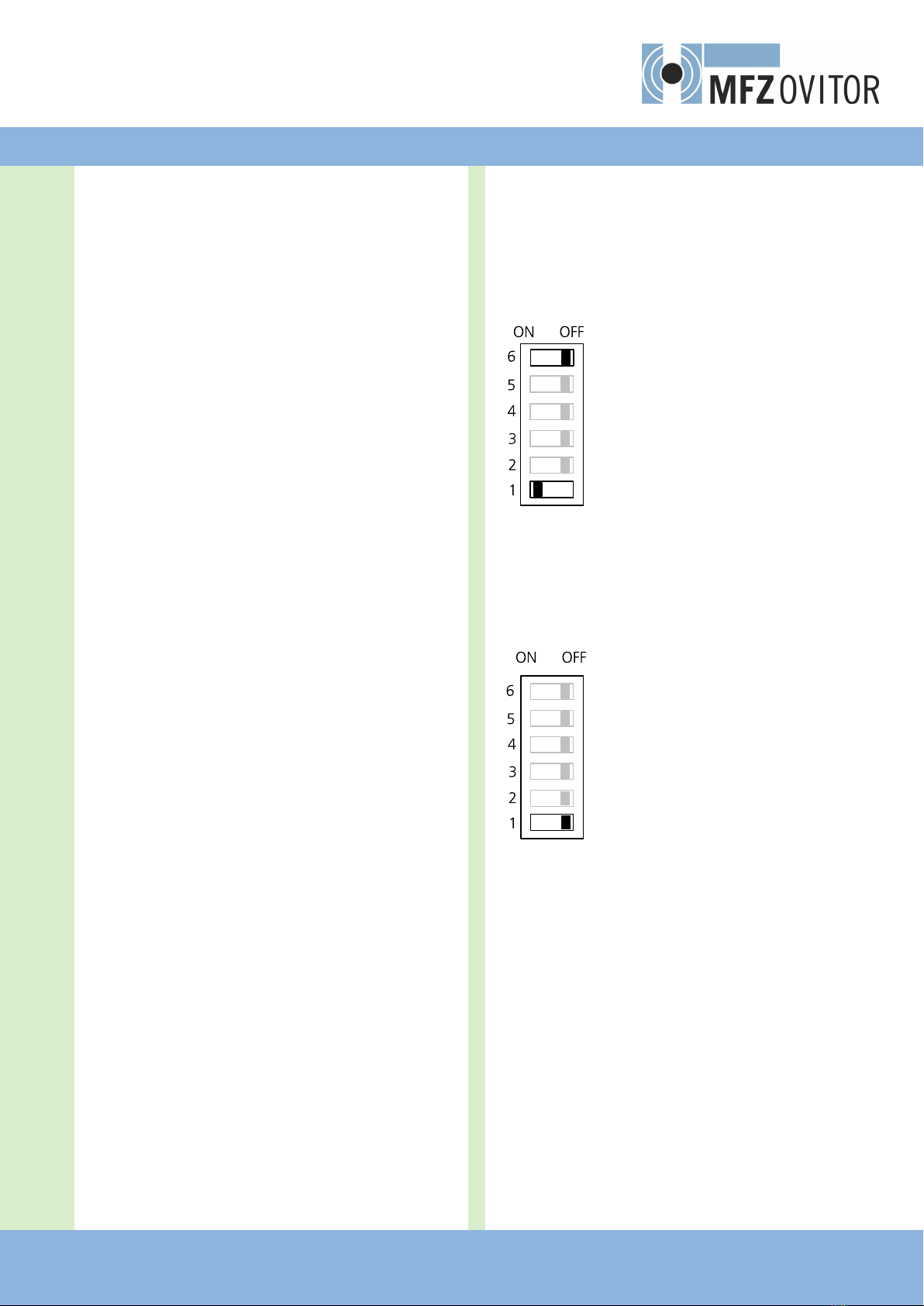
5.10 DIP switches:
1ON DooroperatortypesFT(+HY)*
1OFF DooroperatortypesFDF+FTA
2 ON Fire alarm as normally open contact
2 OFF Fire alarm as normally closed contact
3ON Emergencyclosingwith400VAC/24VDC
3OFF Emergencyclosingwith24VDC
4ON WithCESD(SKS)inemergencyoperation
4OFF WithoutCESD(SKS)inemergencyoperation
5 ON Door closes if an error occurs
5 OFF Door remains open if an error occurs
6ON (OperatortypeHY)*
6 OFF Operator type FT
WhenmakingchangestotheDIPswitchsettings,thefollow-
ing procedure must be observed:
1. Switchoffthemainsvoltage
2. Switchofftherechargeablebatteryvoltage
3. Change the DIP switch positions as required
4. Switchontherechargeablebatteryvoltage
5. Switchonthemainsvoltage
*versionHYonly
5.11 Types of door operator
TheFS345controlisdesignedforusewithtwodifferent
types of door operator.
FT operators
DIP 1 ON and DIP 6 OFF
1.FTdooroperatorswith24VDCmotor
braking.
Inemergencymode,thedoorisclosedviathe
24VDCauxiliarymotor.
The weight of the door is held by the ener-
gised motor brake.
The power supply comes from the mains
adapterontheFS101circuitboard;ifthe
mainspowerisinterrupted,powerissupplied
from the rechargeable battery.
(DIP6ONrequiredforversionHY)
FD (FDF, FTA, FDS) operators
DIP 1 OFF
1.FD(FDF,FTAandFDS)dooroperatorswith
a24VDCauxiliarymotorand24VDCmotor
brake(FDF5).Inemergencymode,thedooris
closedviathe24VDCauxiliarymotor.
The power supply comes from the mains
adapterontheFS101circuitboard;ifthe
mainspowerisinterrupted,powerissupplied
from the rechargeable battery.

14 – FS 345 Door Controls / Rev. A 0.0
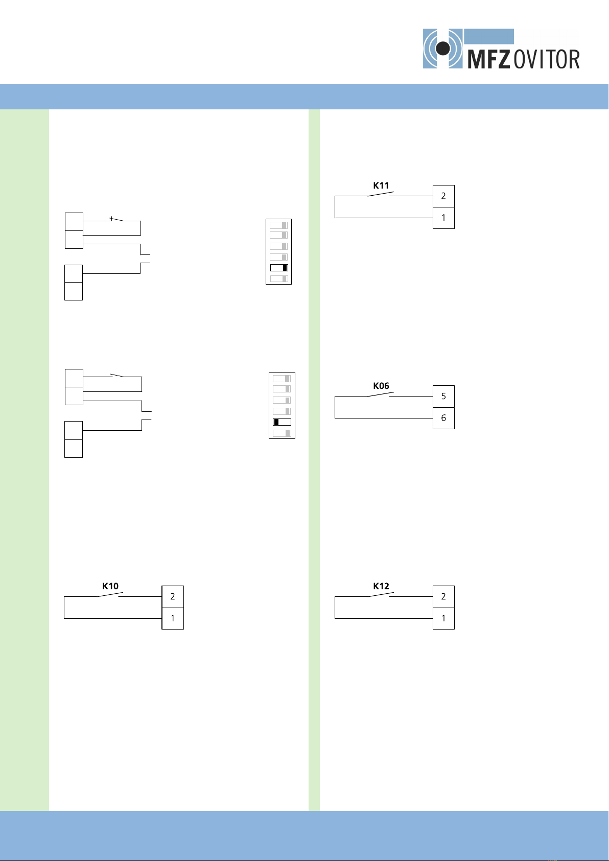
5.12 FS 101 connections
2
1
2
1
2
1
2
1
2
1
X09
X08
X07
X06
X10
X051 2 3 4 5 6X03
X04
M
+
-
* refer to the appendix for connection details for operators FT 3 and FDF 60
CESD(SKS)
Potential-free relay
EMERGENCYOPERATION
Potential-free relay
OPERATION/ERROR
Potential-free relay
INPUT
FIREALARM
24VDC/50mA
Potential-free relay
OPEN/CLOSEcommand
MotorbrakeforFT/FDFoperators*
Auxiliarymotor*
Initial operation
GB
FS 345 Door Controls / Rev.A 0.0 – 15
5.13 Connection example for re alarm con-
tact
Terminal strip X06
(potential-free continuous contact as normally closed contact)
2
1
X06/FS101 Dip 2 = OFF
1
2
3
4
ON OFF
5
6
2
X10/FS101 +
-
1
Terminal strip X06
(potential-free continuous contact as normally open contact)
Dip 2 = ON
1
2
3
4
ON OFF
5
6
2
1
X06/FS101
2
X10/FS101 +
-
1
5.14 Messages
Terminal strip X07
K10operation/errorrelay
X07/FS101
Innormaloperationcontactclosed,opensintheeventofan
error.
Rechargeablebatteryfault/mainspowerfailure:switchesif
the battery is defective or if the battery voltage is less than
19V.
Fire alarm contact
Supplyvoltage
24VDC,max.50mA
Fire alarm contact
Supplyvoltage
24VDC,max.50mA
Terminal strip X08
K11emergencyclosingrelay
X08/FS101
Potential-free switching contact for emergency operation is
active.Switchesintheeventofemergencyclosing(contact
closed).
Terminal block X4
K06operatorcommandrelay
X04/FS101
Potential-freeswitchingcontactforCLOSEorOPENcommand
depending on DIP switches 1 and 3.
(See12and13.1forwiringandfunction)
Terminal strip X09
K12closingedgesafetyedge(SKS)relay
X09/FS101
Potential-freeswitchingcontact,displaysstatusofCESD(SKS)

16 – FS 345 Door Controls / Rev. A 0.0
6. Limit switches
6.1 Limit switches
Connectionarrangementforlimitswitches(CS300terminals
X11,X10andFS101terminalsX03,X05)
1
2
3
4
5
6
7
8
X03/FS101**
1
2
3
4
5
6
7
8
9
10
8
7
6
5
4
3
2
1
6
5
4
3
2
1
5678
X05/FS101*
X11/CS300 FS
X10/CS300 FS*
1
2
3
1 Limit switch OPEN
2LimitswitchCLOSE
3Pre-limitswitchCLOSE
5Thermalprotection,motor*
6 Emergency operation (normally closed contact)**
7SafetylimitswitchCLOSE
8SafetylimitswitchOPEN
* ready wired
** ready wired if supplied with operator
The limit switches (with the exception of the pre-limit switch)
areanalysedbytheFS101circuitboard,andthevaluesare
passedontotheCS300FScircuitboard.
TheassignmentofterminalX11(limitswitch)isdifferent
fromtheassignmentgiventoterminalsintheAS130.This
mustbetakenintoaccountintheeventofretrots
Safety
circuit
-
+
CLOSE
OPEN

GB
FS 345 Door Controls / Rev.A 0.0 – 17
6.2 FDF / FTA / FDS limit switch settings
1. AdditionalOPENlimitswitch green
2. Limit switch OPEN green
3. SafetylimitswitchOPEN red
4. SafetylimitswitchCLOSED red
5. LimitswitchCLOSED white
6. AdditionallimitswitchCLOSED white
NOTICE
Damage to property or irreparable damage due to
incorrect adjustment!
The door can be damaged if it is driven beyond the end
positionwhileadjustmentsarebeingmade.
1. SelecttheADJUSTMENTmenuonthedisplay
2. MovethedoortothedesiredCLOSEDpositionwiththe+
and - buttons.
3. Setcontrolcam5(white)sothatthelimitswitchisactu-
ated.
4. TightenfasteningscrewA.
5. ScrewBcanbeusedtocarryoutnetuning.
6. MovethedoortothedesiredOPENpositionwiththe+
and - buttons.
7. Setcontrolcam2(green)sothatthelimitswitchisactu-
ated.
8. TightenfasteningscrewA.
9. Safetylimitswitches3and5(red)mustbesetsothat
they are triggered as soon as the control limit switches are
crossed.
10. Afterthetrialrun,checkthetightnessofthefastening
screws.
11. Auxiliarylimitswitches1and6haveapotential-free
changeover contact

18 – FS 345 Door Controls / Rev. A 0.0
7.1 Overview of the LCD monitor
AUTOMATIC O
STANDBY
A
B
C D E
F
G
H
Key:
A: Modeofoperation/DIAGNOSISinfo
B: Parameters/DIAGNOSISinfo
C Button(+)
D: Button (-)
E Button (P)
F Value/status
G Value/status
H Jumper
7.2 LCD monitor, modes of operation
The control has four modes of operation with the LCD moni-
tor:
1.AUTOMATIC
2.ADJUSTMENT
3.INPUT
4.DIAGNOSIS
IfjumperHisremoved,the(+)button,the(-)buttonandthe
(P) button have no function.
The display still functions.
Afterswitchingthecontrolon,itisinINITIALISATIONmode.
ThedisplayshowsINITPHASEandthecontrolisnotyetready
for use. This phase lasts approx. 5 seconds.
7. Programming with the LCD monitor
6.3 FT limit switch settings
2. Limit switch OPEN green
3. SafetylimitswitchOPEN red
4. SafetylimitswitchCLOSED red
5. LimitswitchCLOSED white
6. AuxiliarylimitswitchCLOSED white
NOTICE
Damage to property or irreparable damage due to
incorrect adjustment!
The door can be damaged if it is driven beyond the end
positionwhileadjustmentsarebeingmade.
1. SelecttheADJUSTMENTmenuonthedisplay
2. MovethedoortothedesiredCLOSEDpositionwiththe+
and - buttons.
3. Setcontrolcam5(white)sothatthelimitswitchisactu-
ated.
4. TightenfasteningscrewA.
5. ScrewBcanbeusedtocarryoutnetuning.
6. MovethedoortothedesiredOPENpositionwiththe+
and - buttons.
7. Setcontrolcam2(green)sothatthelimitswitchisactu-
ated.
8. TightenfasteningscrewA.
9. Safetylimitswitches3and4(red)mustbesetsothat
they are triggered as soon as the control limit switches are
crossed.
10. Afterthetrialrun,checkthatthefasteningscrewsarecor-
rectly tightened.
11. Auxiliarylimitswitches1and6haveapotential-free
changeover contact
Limit switches

GB
FS 345 Door Controls / Rev.A 0.0 – 19
ADJUSTMENT,INPUTandDIAGNOSISmodesareexitedau-
tomatically20secondsafterthelastbuttonwaspressed,and
thecontrolthengoesintoAUTOMATICmode.
Operating mode 1: AUTOMATIC
ThedoorsystemisoperatedinAUTOMATICoperatingmode.
Display:
− Displaystheactionbeingcarriedout
− Displaysanyerrors
Ifthe“PRESS/REL"parameterissettoMOD2orMOD3in
theinputmenu,thedisplaychangesfromAUTOMATICto
MANUAL.
Operating mode 2: ADJUSTMENT
InADJUSTMENTmode,theOPEN/CLOSEDendpositionsare
set.
NOTICE
Malfunctions can occur as a result of incorrect
operation of the control!
InADJUSTMENTmode,thedoorwillnotstopautomatically
when it reaches the travel limit position if electronic end
positions(AWG)areused.
The door can be damaged if driven beyond the end posi-
tion.
FineadjustmentscanbemadeintheINPUToperatingmode.
Display:
− Displaysthetravellimitvalue
Operating mode 3: INPUT
IntheINPUToperatingmode,thevaluesofvariousparam-
eters can be altered.
Display:
− Displaystheselectedparameter
− Displaysthecurrentvalueorstatus
Operating mode 4: DIAGNOSIS
IntheDIAGNOSISoperatingmode,door-speciccheckscan
be queried.
Display:
− Displaysthemonitoredfunction
− Displaysthestatusofthefunction

20 – FS 345 Door Controls / Rev. A 0.0
8. Navigator (LCD monitor only)
AUTOMATIC
STANDBY
P
> 1 second
ADJUSTMENT
STANDBY
+
->Position,DOOROPEN ADJUSTMENT
MAINUP Deadman operation
Setthemechanicallimit
switches as described in sec-
tion 22.
-
->PositionDOORCLOSED ADJUSTMENT
MAINDOWN
P
> 1 second
INPUT
+
and
-
> 2 sec. INPUT
ENGLISH : Scrollupthroughmenu:
+
> 2 sec.
Scrolldownthroughmenu:
-
> 2 sec.
Selectvalue:
P
> 1 sec.
Increase value:
+
Decrease value:
-
Savevalue:
P
Return to INPUTmode:
+
and
-
> 1 sec
INPUT
RUNTIME : 60
P
> 1 second
INPUT
OPEN TIME : 0
INPUT
PREWARNING : 0
INPUT
REVERS.TIME : 3
INPUT
MOD1-3STANDBY : MOD1
INPUT
QUICKCLOSE : OFF
INPUT
RELAY1 : MOD6
INPUT
RELAY2 : MOD7
INPUT
RELAY3 : MOD1
INPUT
RELAY4 : MOD19
INPUT
DW-TEST : OFF
INPUT
DELAYUP : OFF
INPUT
PRESS/REL : MOD1
INPUT
SU/WI : MOD1
INPUT
REVERS. : MOD1
DIAGNOSIS
Scrollupthroughmenu:
+
> 2 sec.
Scrolldownthroughmenu:
-
> 2 sec.
ReturntoAUTOMATICmode:
P
Only queries are possible.
UPPERSWITCH : ON
LOWERSWITCH : OFF
UPSWITCH : OFF
PARTUP : OFF
DOWNSWITCH : OFF
SKS : OFF
IMP.INPUT : OFF
SWITCHCLOCK : OFF
LIGHTBARR. : ON
STOPCIRCUIT : ON
S-POINT1 : ON
S-POINT2 : ON
CYCLE : XXXX
Table of contents
Other MFZ Ovitor Control System manuals


Popular Control System manuals by other brands


Carrier
Carrier AQUASNAP 30RA/RH Operation & maintenance instructions

Genius
Genius 433RC Series quick start guide

ICS
ICS Auto Sentry Petro installation guide

Faulhaber
Faulhaber 3564K024B CS instruction manual

TeeJet Technologies
TeeJet Technologies Dynajet FLEX 7140 INSTALLATION, SETUP AND USER GUIDE

Balboa
Balboa Hydro Air 20-0244 quick start guide


