manuals.online logo
Brands
  1. Home
  2. •
  3. Brands
  4. •
  5. HEIDENHAIN
  6. •
  7. Control System
  8. •
  9. HEIDENHAIN MANUALPLUS 620 User manual

HEIDENHAIN MANUALPLUS 620 User manual

Other manuals for MANUALPLUS 620

2

Other HEIDENHAIN Control System manuals

HEIDENHAIN ITNC 530 - CONVERSATIONAL PROGRAMMING User manual

HEIDENHAIN

HEIDENHAIN ITNC 530 - CONVERSATIONAL PROGRAMMING User manual

HEIDENHAIN AK LIC 413 User manual

HEIDENHAIN

HEIDENHAIN AK LIC 413 User manual

HEIDENHAIN ND 780 User manual

HEIDENHAIN

HEIDENHAIN ND 780 User manual

HEIDENHAIN POSITIP 880 User manual

HEIDENHAIN

HEIDENHAIN POSITIP 880 User manual

HEIDENHAIN ECN 413 2C User manual

HEIDENHAIN

HEIDENHAIN ECN 413 2C User manual

HEIDENHAIN TNC 320 User manual

HEIDENHAIN

HEIDENHAIN TNC 320 User manual

HEIDENHAIN ITNC 530 - CONVERSATIONAL PROGRAMMING User manual

HEIDENHAIN

HEIDENHAIN ITNC 530 - CONVERSATIONAL PROGRAMMING User manual

HEIDENHAIN TNC 620 Programming Station User manual

HEIDENHAIN

HEIDENHAIN TNC 620 Programming Station User manual

HEIDENHAIN ITNC 530 - CONVERSATIONAL PROGRAMMING User manual

HEIDENHAIN

HEIDENHAIN ITNC 530 - CONVERSATIONAL PROGRAMMING User manual

HEIDENHAIN iTNC 530 HSCI User manual

HEIDENHAIN

HEIDENHAIN iTNC 530 HSCI User manual

HEIDENHAIN TNC 620 User manual

HEIDENHAIN

HEIDENHAIN TNC 620 User manual

HEIDENHAIN AK ECM 2410 User manual

HEIDENHAIN

HEIDENHAIN AK ECM 2410 User manual

HEIDENHAIN TNC 150 B User manual

HEIDENHAIN

HEIDENHAIN TNC 150 B User manual

HEIDENHAIN LIF 181 R User manual

HEIDENHAIN

HEIDENHAIN LIF 181 R User manual

HEIDENHAIN TNC 370 D Manual

HEIDENHAIN

HEIDENHAIN TNC 370 D Manual

HEIDENHAIN TNC 407 User manual

HEIDENHAIN

HEIDENHAIN TNC 407 User manual

HEIDENHAIN TNC 426 B User manual

HEIDENHAIN

HEIDENHAIN TNC 426 B User manual

HEIDENHAIN POSITIP 880 User manual

HEIDENHAIN

HEIDENHAIN POSITIP 880 User manual

HEIDENHAIN ITNC 530 - CONVERSATIONAL PROGRAMMING User manual

HEIDENHAIN

HEIDENHAIN ITNC 530 - CONVERSATIONAL PROGRAMMING User manual

HEIDENHAIN LIP 471R User manual

HEIDENHAIN

HEIDENHAIN LIP 471R User manual

HEIDENHAIN TNC151B Operating instructions

HEIDENHAIN

HEIDENHAIN TNC151B Operating instructions

HEIDENHAIN TNC 150 B User manual

HEIDENHAIN

HEIDENHAIN TNC 150 B User manual

HEIDENHAIN TNC 620 User manual

HEIDENHAIN

HEIDENHAIN TNC 620 User manual

HEIDENHAIN TNC 320 User manual

HEIDENHAIN

HEIDENHAIN TNC 320 User manual

Popular Control System manuals by other brands

Comunello BORDER 400 Installation and user manual

Comunello

Comunello BORDER 400 Installation and user manual

Verlinde EUROBLOC Variator VTN Service manual

Verlinde

Verlinde EUROBLOC Variator VTN Service manual

Diginet DGOZ-TCSW-LR35 installation guide

Diginet

Diginet DGOZ-TCSW-LR35 installation guide

VADDIO ControlVIEW Xtreme manual

VADDIO

VADDIO ControlVIEW Xtreme manual

Duke HSHU 13 SERIES Installation and operation manual

Duke

Duke HSHU 13 SERIES Installation and operation manual

AIRTRONICS Blazer Sport manual

AIRTRONICS

AIRTRONICS Blazer Sport manual

Pentair Pool Products Compool Installation and user guide

Pentair Pool Products

Pentair Pool Products Compool Installation and user guide

ComfortNET CTK04 manual

ComfortNET

ComfortNET CTK04 manual

CAME G3000 installation manual

CAME

CAME G3000 installation manual

Idemia MorphoAccess VP MD installation guide

Idemia

Idemia MorphoAccess VP MD installation guide

Doosan DVF Series Operation user's manual

Doosan

Doosan DVF Series Operation user's manual

Axis P1445-LE-3 user manual

Axis

Axis P1445-LE-3 user manual

CNC-Step High-Z T-Series operating instructions

CNC-Step

CNC-Step High-Z T-Series operating instructions

Honeywell KAP 140 Maintenance manual

Honeywell

Honeywell KAP 140 Maintenance manual

Honeywell vk41 series Handbook

Honeywell

Honeywell vk41 series Handbook

Cypress HHR-3160 product manual

Cypress

Cypress HHR-3160 product manual

Zonex GEN II -VVT Installation and application manual

Zonex

Zonex GEN II -VVT Installation and application manual

Altronics K 9650 quick start guide

Altronics

Altronics K 9650 quick start guide

manuals.online logo
manuals.online logoBrands
  • About & Mission
  • Contact us
  • Privacy Policy
  • Terms and Conditions

Copyright 2025 Manuals.Online. All Rights Reserved.

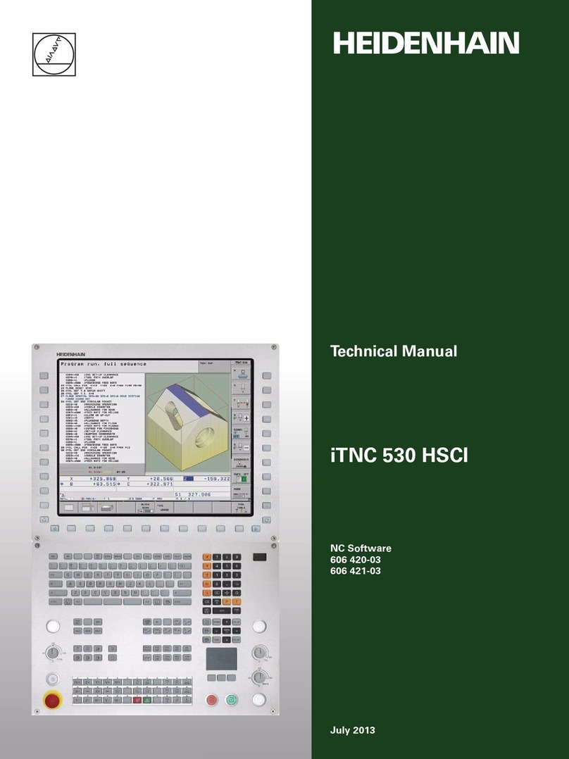
Technical Manual
MANUALplus 620
NC Software
548 328-04
January 2012
January 2012 3
Contents
1 Update Information No. 1........................19
1.1 Overview............................................................................................19
1.2 NC Software 548 328-02...................................................................19
1.2.1 Important notes on updating software .................................19
1.2.2 Description of the new functions..........................................26
1 Update Information No. 2........................37
1.1 Overview............................................................................................37
1.2 NC Software 548 328-03...................................................................37
1.2.1 Important notes on updating software .................................37
1.2.2 Description of the new functions..........................................39
1 Update Information No. 3........................47
1.1 Hardware ...........................................................................................47
1.1.1 UEC 11x controller unit with inverter and PLC I/O................47
1 Update Information No. 4........................51
1.1 Overview............................................................................................51
1.1.1 Released service packs.........................................................51
1.1.2 Released NC software..........................................................51
1.2 NC Software 548 328-03...................................................................51
1.3 NC Software 548 328-04...................................................................52
1.3.1 Important change made in the technical manual ..................52
1.3.2 Important notes on updating software .................................53
1.3.3 Description of the new functions..........................................57
1.4 Hardware ...........................................................................................78
1.4.1 CMA-H SPI module for analog axes......................................78
4 HEIDENHAIN Technical Manual MANUALplus 620
2 Introduction...............................................79
2.1 Meaning of the Symbols Used in this Manual...............................79
2.2 Proper and Intended Operation.......................................................79
2.3 Trained Personnel .............................................................................79
2.4 General Information..........................................................................80
2.4.1 HSCI interface.......................................................................83
2.5 Component Overview of MANUALplus 620..................................84
2.5.1 MC main computer, CFR memory card and SIK...................84
2.5.2 SIK (System Identification Key).............................................86
2.5.3 CC 61xx controller units........................................................86
2.5.4 UEC 11x controller unit with integrated inverter and PLC ....87
2.5.5 PLC input/output systems with HSCI interface ....................89
2.5.6 SPI expansion modules.........................................................93
2.5.7 PSL 13x low-voltage power supply unit................................94
2.5.8 MB 620T machine operating panel.......................................96
2.5.9 HSCI adapter for PLB 6001 OEM-specific machine
operating panel .....................................................................97
2.5.10 Handwheels..........................................................................98
2.5.11 Key symbols........................................................................101
2.5.12 Touch probes ......................................................................106
2.5.13 Other accessories...............................................................109
2.5.14 Documentation ...................................................................110
2.6 Brief Description..............................................................................111
2.6.1 Specifications for MANUALplus 620 ..................................111
2.6.2 User functions.....................................................................117
2.6.3 Software options.................................................................122
2.6.4 Accessories.........................................................................123
2.7 Software ..........................................................................................125
2.7.1 Designation of the software ...............................................125
2.7.2 PLC software ......................................................................125
2.7.3 Additional control loops or software options ......................126
2.7.4 Configurations.....................................................................136
2.7.5 Coordinate system of the lathe...........................................137
2.7.6 NC software exchange on the MANUALplus 620 ..............137
2.7.7 Installing a service pack ......................................................143
2.7.8 Reversing a software update..............................................144
2.7.9 Special features of the software.........................................146
2.7.10 Firmware update on HSCI devices .....................................147
2.7.11 Monitoring hardware changes ............................................149
2.7.12 Data backup ........................................................................149
2.8 Software Releases ..........................................................................150
2.8.1 NC software 548 328-xx .....................................................150
January 2012 5
3 Mounting and Electrical Installation.....151
3.1 General Information........................................................................151
3.1.1 Safety precautions ..............................................................151
3.1.2 Degrees of protection.........................................................152
3.1.3 Electromagnetic compatibility.............................................152
3.1.4 ESD protection....................................................................153
3.2 Environmental Conditions .............................................................155
3.2.1 Storage and operating temperatures ..................................155
3.2.2 Heat generation and cooling ...............................................157
3.2.3 Limit values for ambient conditions....................................158
3.2.4 Installation elevation ...........................................................158
3.2.5 UEC 11x (FS) mounting position.........................................159
3.2.6 MC 6110T mounting position .............................................160
3.2.7 CC 61xx, UV xxx, UM xxx, UE 2xx B(D) mounting position161
3.2.8 PLB 6xxx mounting position ...............................................162
3.3 Overview of Components ..............................................................163
3.4 HSCI..................................................................................................168
3.4.1 Introduction.........................................................................168
3.4.2 Topology .............................................................................170
3.4.3 HSCI interface.....................................................................171
3.5 MANUALplus 620 Connection Overview......................................172
3.5.1 MC 6110T main computer..................................................172
3.5.2 CC 6106 ..............................................................................173
3.5.3 CC 6108 ..............................................................................174
3.5.4 CC 6110 ..............................................................................175
3.5.5 UEC 11x..............................................................................176
3.5.6 PLB 62xx.............................................................................177
3.5.7 PLB 61xx.............................................................................177
3.5.8 PLD-H and PLA-H I/O modules...........................................178
3.6 Supply Voltages in the HSCI System............................................180
3.6.1 Current consumption of the HSCI components..................182
3.6.2 X90: +24 V NC output of the UxC 11x (FS).........................183
3.6.3 X101: NC power supply ......................................................184
3.6.4 Power supply of the CC 61xx .............................................185
3.6.5 PSL 13x low-voltage power supply unit..............................189
3.7
MS 110 / MS 111 Installation Kit for Double-Row Configuration ....199
3.7.1 General information ............................................................199
3.7.2 Double-row configuration....................................................200
3.7.3 Connection overview ..........................................................202
3.8 UxC 11x (FS): Power Supply and Motor Connection...................206
3.8.1 UEC 11x (FS).......................................................................206
3.9 UxC 11x (FS): Meaning of the LEDs...............................................212
3.10 Power Supply for PLC Outputs......................................................214
3.11 Power Supply for PLB 6xxx (FS)....................................................216
3.12 Meaning of the LED on PLB 6xxx ..................................................217
3.13 Power Supply for Control-Is-Ready Signal...................................217
3.14 Drive Controller Enable ..................................................................218
6 HEIDENHAIN Technical Manual MANUALplus 620
3.15 Digital PLC Inputs/Outputs............................................................219
3.15.1 UxC 11x (FS): Digital PLC inputs/outputs............................228
3.16 Analog PLC Inputs/Outputs...........................................................235
3.17 PROFIBUS Connection....................................................................237
3.18 Configuring the PLC Inputs/Outputs with IOconfig ....................238
3.19 Buffer Battery ..................................................................................241
3.20 Encoder Connections .....................................................................242
3.20.1 General information ............................................................242
3.20.2 Position encoder input .......................................................243
3.20.3 Speed encoder input .........................................................246
3.21 Adapters for Encoder Signals ........................................................250
3.22 Connecting the Motor Power Modules (Only CC 61xx) ..............254
3.23 Analog Nominal Value Output ......................................................255
3.23.1 CMA-H 04-04-00 – Pin layout..............................................257
3.24 Touch Probe Systems.....................................................................260
3.25 Data Interfaces ................................................................................265
3.25.1 USB interface (USB 2.0)......................................................268
3.26 MB 620T Machine Operating Panel...............................................269
3.27
HSCI Adapter for PLB 6001 OEM-Specific Machine Operating Panel
....278
3.28 Handwheel Input.............................................................................287
3.28.1 HR 410 portable handwheel ...............................................287
3.28.2 HR 130 panel-mounted handwheel ....................................289
3.28.3 HRA 110 handwheel adapter..............................................290
3.29 CML 110 Capacitor Module............................................................292
3.30 Connecting Cables: Specifications ................................................294
3.31 Dimensions......................................................................................295
3.31.1 MC 6110T ...........................................................................296
3.31.2 MB 620T .............................................................................297
3.31.3 CC 6106 ..............................................................................298
3.31.4 CC 6108 / CC 6110 .............................................................299
3.31.5 UEC 11x (FS).......................................................................300
3.31.6 PL 6xxx (FS) ........................................................................301
3.31.7 PLB 6001(FS) ......................................................................302
3.31.8 PSL 130...............................................................................303
3.31.9 PSL 135...............................................................................304
3.31.10 MS 11x................................................................................305
3.31.11 Adapter block for the data interface....................................306
3.31.12 USB hub..............................................................................307
3.31.13 Line-drop compensator.......................................................308
3.31.14 Handwheels........................................................................308
3.31.15 Touch probes ......................................................................311
3.31.16 CML 110 .............................................................................318
3.31.17 USB hub for operating panel...............................................318
3.32
HSCI Connection Overview of the MANUALplus 620 with CC 61xx
.....319
3.33
HSCI Connection Overview of the MANUALplus 620 with UEC 11x
.....320
January 2012 7
3.34 Grounding Diagram for MANUALplus 620 with Modular
HEIDENHAIN Inverter System .......................................................321
3.35 Basic Circuit Diagram for MANUALplus 620 ................................322
3.36 Cable Overview for MANUALplus 620 with UEC 11x – Basic
Configuration...................................................................................323
3.37 Cable Overview for MANUALplus 620 with CC 610x – Basic
Configuration...................................................................................324
3.38 Cable Overview for HEIDENHAIN Inverter System......................325
3.39 Cable Overview for MANUALplus 620 – Accessories ..................326
4 Machine Parameters...............................327
4.1 General Information........................................................................327
4.2 The "Machine Parameters" Mode of Operation...........................329
4.2.1 Calling the configuration editor ...........................................329
4.2.2 Entering and changing machine parameters.......................331
4.2.3 Accessing machine parameters via MP numbers...............342
4.2.4 Managing configuration files...............................................345
4.2.5 Sorting file content..............................................................346
4.2.6 Attribute information...........................................................347
4.2.7 Access protection / Options................................................350
4.2.8 Update rules........................................................................351
4.2.9 Removing syntax errors......................................................362
4.2.10 Resetting the update version..............................................362
4.2.11 Backup of parameters.........................................................363
4.2.12 Resetting system settings..................................................364
4.3 User Parameters..............................................................................365
4.3.1 Configuration of the user parameters.................................366
4.3.2 Example: .............................................................................372
4.3.3 XML commands for creating the layout files......................374
4.4 The KeySynonym Function............................................................377
4.5 Allocation of Configuration Data ..................................................379
4.6 Structure of a Parameter File.........................................................380
4.7 Machine-Parameter Subfiles..........................................................383
4.7.1 Syntax of machine-parameter subfile .................................383
4.7.2 Activating the machine-parameter subfile ..........................384
4.7.3 Displaying/editing data records in the configuration editor .387
4.8 Reading or Changing Machine Parameters via PLC Modules.....389
4.9 Switching Parameter Sets .............................................................398
4.10 List of Machine Parameters ...........................................................408
4.10.1 "System" group....................................................................408
4.10.2 "Channels" group.................................................................490
4.10.3 "Axes" group........................................................................510
4.10.4 KeySynonym.......................................................................582
4.10.5 Aggregates..........................................................................583
4.10.6 ProcessingData...................................................................595
8 HEIDENHAIN Technical Manual MANUALplus 620
5 Modules and PLC Operands ..................599
5.1 Overview of Modules......................................................................599
5.2 Overview of the PLC Operands......................................................604
5.2.1 PLC operands of the General Data group ...........................604
5.2.2 PLC operands of the Operating Mode Group group...........606
5.2.3 PLC operands of the Machining Channels group................607
5.2.4 PLC operands of the Axis group .........................................609
5.2.5 PLC operands of the Spindle group ....................................611
6 Configuring the Axes and Spindle ........613
6.1 Machine Structure ..........................................................................613
6.1.1 Adapting the MANUALplus 620 to the machine.................613
6.1.2 Definition of axes................................................................614
6.2 Configuration of Machining Channels ..........................................617
6.2.1 Configuring a machining channel........................................617
6.2.2 Traversing the reference marks..........................................621
6.2.3 Returning to the contour/block scan...................................622
6.3 Configuration of Axes.....................................................................624
6.3.1 Axis designations and coordinates......................................626
6.3.2 Programmable axes ............................................................628
6.3.3 Physical axes.......................................................................631
6.3.4 Kinematic properties of axes ..............................................641
6.3.5 Manually operated axis (counter axis).................................643
6.4 Encoders ..........................................................................................645
6.4.1 Type of position encoder ....................................................645
6.4.2 Signal period of encoders ...................................................648
6.4.3 Distance-coded reference marks ........................................654
6.4.4 Connecting the encoders, PWM output on the CC 61xx....656
6.4.5 Connecting the encoders to the UEC 11x ..........................661
6.4.6 Defining the traverse direction............................................663
6.4.7 Encoder monitoring.............................................................665
6.5 Analog Axes.....................................................................................669
6.5.1 Central drive........................................................................670
6.6 Reading and Writing Axis Information .........................................671
6.6.1 Reading axis information.....................................................671
6.6.2
Writing axis information—activating and deactivating axes
.....678
6.7 Traverse Ranges..............................................................................688
6.8 Lubrication Pulse.............................................................................690
6.9 PLC Axes ..........................................................................................692
6.9.1 Hirth coupling......................................................................702
6.10 Axis Error Compensation ...............................................................705
6.10.1 Backlash compensation ......................................................707
6.10.2 Linear axis error compensation...........................................711
6.10.3 Nonlinear axis error compensation .....................................713
6.10.4 Compensation of thermal expansion ..................................721
6.10.5 Compensation of static friction...........................................723
6.10.6 Compensation of sliding friction .........................................724
January 2012 9
6.11 Machine Kinematics (As of NC Software 548328-03) ..................727
6.11.1 Configuring the machine kinematics...................................730
6.11.2 Preconfigured subkinematics..............................................739
6.11.3 Standard kinematic models.................................................742
6.11.4 Finding/activating kinematics through the PLC...................744
6.11.5 Axis mirroring on lathes (as of NC software 548328-03) ....746
6.12 Machine Kinematics (Up to NC Software 548 328-02) ................747
6.12.1 Configuration of the machine kinematics ...........................748
6.12.2 Definition of the transformation with vectors.....................758
6.12.3 Axis mirroring for lathes......................................................761
6.13 Parallel Axes ....................................................................................762
6.14 Synchronized Axes (Option 24) .....................................................764
6.14.1 Gantry axes.........................................................................765
6.14.2 Master-slave torque control................................................775
6.14.3 Brake test for synchronized axes........................................784
6.15 Reference Marks..............................................................................789
6.15.1 Definition.............................................................................789
6.15.2 Traversing the reference marks..........................................790
6.15.3 Traversing the reference marks..........................................794
6.15.4 Defining the process of traversing the reference marks ....797
6.15.5 "Traverse Reference Points" operating mode .....................804
6.16 The Control Loop ............................................................................808
6.16.1 Block diagram of control loop .............................................808
6.16.2 Relation between jerk, acceleration, velocity and distance 809
6.16.3 Nominal position value filter................................................811
6.16.4 Look-ahead..........................................................................825
6.16.5 Interpolator..........................................................................838
6.16.6 Position controller ...............................................................839
6.16.7 Activating and deactivating position control loops..............848
6.16.8 Feed-rate enable .................................................................852
6.16.9 Speed controller..................................................................853
6.16.10 Filters in the speed controller and position controller
when using the CC 61xx and CC 424 .................................857
6.16.11 Filter order for separate low-pass filter in the speed
controller on the CC 61xx and CC 424: ..............................861
6.16.12 Peculiarities in weakened-field operation with CC 61xx
and CC 424 .........................................................................862
6.16.13 Active damping of low-frequency oscillations.....................864
6.16.14 Acceleration feedforward control........................................866
6.16.15 IPC, holding torque, following error in the jerk phase.........869
6.16.16 HSCI: switching drives on and off, enabling the drive
controller.............................................................................874
6.16.17 Current controller ................................................................885
6.16.18
Braking the drives for an emergency stop and a power failure
....890
6.16.19 Power and torque limiting...................................................894
6.16.20 Controller parameters for manual traverse .........................901
6.16.21 Controller parameters for analog axes................................902
6.16.22 Controller parameters for analog axes................................913
6.16.23 Weakened field operation...................................................924
6.16.24 Motor with wye/delta switchover .......................................936
6.16.25 Speed-dependent switching of the PWM frequency..........938
6.16.26 TRC – Torque Ripple Compensation ...................................941
6.16.27 Torsion compensation.........................................................944
10 HEIDENHAIN Technical Manual MANUALplus 620
6.17 Monitoring Functions .....................................................................946
6.17.1 Monitoring the drives..........................................................946
6.17.2 Position monitoring.............................................................948
6.17.3 Movement monitoring ........................................................953
6.17.4 Standstill monitoring ...........................................................955
6.17.5 Positioning window.............................................................956
6.17.6 Monitoring of the power supply unit ..................................959
6.17.7 Temperature monitoring .....................................................962
6.17.8 I2t monitoring......................................................................965
6.17.9 Momentary utilization of drive motors................................977
6.17.10 Status of HEIDENHAIN hardware and software.................979
6.17.11 Motor brake ........................................................................983
6.17.12 Emergency stop monitoring................................................989
6.17.13
Monitoring functions when using the CC 61xx and CC 424
........996
6.18 Spindles ...........................................................................................998
6.18.1 Configuring spindles ...........................................................998
6.18.2 Spindle in position feedback control .................................1000
6.18.3 Spindle in speed control....................................................1009
6.18.4 Filtering the acceleration values........................................1014
6.18.5 Controlling the spindle ......................................................1015
6.18.6 Switching the operating modes ........................................1029
6.18.7 Analog spindle with unipolar motor ..................................1032
6.18.8 Spindle synchronism.........................................................1033
6.18.9 Spindle of the kinematics model
(as of NC software 548 328-03)........................................1036
6.18.10 Spindle of the kinematics model
(until NC software 548 328-02).........................................1037
6.18.11 Gear shifting......................................................................1038
6.18.12 Tapping .............................................................................1039
6.18.13 C-axis operation ................................................................1040
6.18.14 Volts-per-hertz control mode.............................................1042
6.19 Configuring the Controller Unit and Drive Motors....................1044
6.19.1 Specifications of CC 61xx / UEC 1xx ................................1044
6.19.2 Structure of the CC 61xx and UEC 11x controller units....1046
6.19.3 PWM frequencies with the CC 61xx ................................1048
6.19.4
PWM frequency with INDRAMAT "POWER DRIVE" inverters ...
1050
6.19.5 PWM frequency with SIEMENS "SIMODRIVE" inverters .1050
6.19.6 Comparison of the CC 61xx and CC 424 controller units..1053
6.19.7 Configuring the drive motor..............................................1055
6.19.8 Field orientation ................................................................1058
6.19.9
Determining the field angle with the CC 61xx und CC 424 ........
1061
6.20 Commissioning .............................................................................1072
6.20.1 Tables for power modules, supply modules and motors..1072
6.20.2 Field orientation ................................................................1084
6.20.3 Preparation........................................................................1084
6.20.4 Commissioning of digital axes ..........................................1089
6.20.5 Commissioning of analog axes .........................................1104
6.20.6 Configuring the nominal position value filter and
look-ahead parameters......................................................1124
6.20.7 Commissioning the digital spindle ....................................1140