MG Energy Systems MGHE240100 User manual
MG Energy Systems B.V. | Foeke Sjoerdswei 3 | 8914 BH Leeuwarden | The Netherlands
Innovation in energy storage
Lithium-Ion HE battery module
- Manual -
MGHE240100, MGHE241100, MGHE242100 (HE 100Ah)
MGHE240150, MGHE241150, MGHE242150 (HE 150Ah)
MGHE240200, MGHE241200, MGHE242200 (HE 200Ah)
MGHE240300, MGHE241300, MGHE242300 (HE 300Ah)
MG Energy Systems B.V.
Revision: 2.2
Date: 11-01-2021

MG Energy Systems B.V. | Foeke Sjoerdswei 3 | 8914 BH Leeuwarden | The Netherlands
Innovation in energy storage
Copyrights 2020 MG Energy Systems B.V.
All Rights Reserved
This publication or parts thereof, may not be reproduced in any form, by any method, for any purpose.
For conditions of use and permission to use this manual for publication in other than the English language,
contact MG Energy Systems B.V..
MG ENERGY SYSTEMS B.V. MAKES NO WARRANTY, EITHER EXPESSED OR IMPLIED, INCLUDING BUT NOT
LIMITED TO ANY IMPLIED WARRANTIES OF MERCHANTABILITY OR FITNESS FOR A PARTICULAR PURPOSE,
REGARDING THESE MG ENERGY SYSTEMS B.V. PRODUCTS AND MAKES SUCH MG ENERGY SYSTEMS B.V.
PRODUCTS AVAILABLE SOLELY ON AN “AS IS” BASIS.
IN NO EVENT SHALL MG ENERGY SYSTEMS B.V. BE LIABLE TO ANYONE FOR SPECIAL, COLLATERAL,
INCIDENTAL, OR CONSEQUENTIAL DAMAGES IN CONNECTION WITH OR ARISING OUT OF PURCHASE OR USE
OF THESE MG ENERGY SYSTEMS B.V. PRODUCTS. THE SOLE AND EXCLUSIVE LIABILITY TO MG ENERGY
SYSTEMS B.V.., REGARDLESS OF THE FORM OF ACTION, SHALL NOT EXCEED THE PURCHASE PRICE OF THE
MG ENERGY SYSTEMS B.V. PRODUCTS DESCRIBED HERE IN.
MG Energy Systems B.V. reserves the right to revise and improve its products as it sees fit. This publication
describes the state of this product at the time of its publication and may not reflect the product at all times
in the future.
MG Energy Systems B.V. | Foeke Sjoerdswei 3 | 8914 BH Leeuwarden | The Netherlands
Innovation in energy storage
TABLE OF CONTENTS
1 GENERAL ...................................................................................................................................................... 6
1.1 Document history ................................................................................................................................ 6
1.2 Terms, abbreviations, and definition................................................................................................... 6
2 SAFETY INSTRUCTIONS................................................................................................................................. 8
2.1 Safety message level definition ........................................................................................................... 8
2.2 User health and safety ......................................................................................................................... 8
General precautions..................................................................................................................... 8
Qualifications and training........................................................................................................... 9
Non-compliance risks................................................................................................................... 9
Unacceptable modes of operation .............................................................................................. 9
3 TRANSPORT, STORAGE AND UNPACKING.................................................................................................. 10
3.1 Transport............................................................................................................................................ 10
3.2 Storage............................................................................................................................................... 10
3.3 Unpacking .......................................................................................................................................... 11
Scope of delivery........................................................................................................................ 11
4 GENERAL DESCRIPTION.............................................................................................................................. 12
4.1 Battery system components .............................................................................................................. 12
4.2 Functional description ....................................................................................................................... 12
4.3 Example systems................................................................................................................................ 13
Low voltage systems .................................................................................................................. 13
High voltage systems ................................................................................................................. 14
5 MODELS ..................................................................................................................................................... 15
5.1 Models and configurations ................................................................................................................ 15
RJ45 connectors and systems up to 96 V................................................................................... 15
M12 connectors and systems up to 96 V................................................................................... 15
M12 connectors and systems up to 460 V systems (M12, HV) ................................................. 15
Battery designation.................................................................................................................... 16
5.2 Identification label ............................................................................................................................. 17
6 OVERVIEW.................................................................................................................................................. 18
6.1 Connection overview ......................................................................................................................... 18
Overview of all models............................................................................................................... 20
6.2 Connections details............................................................................................................................ 24
RJ45 CAN-bus connector details ................................................................................................ 24
MG Energy Systems B.V. | Foeke Sjoerdswei 3 | 8914 BH Leeuwarden | The Netherlands
Innovation in energy storage
M12 CAN-bus connector details ................................................................................................ 25
Power connections..................................................................................................................... 26
6.3 Status indication ................................................................................................................................ 28
Indication ................................................................................................................................... 28
7 INTEGRATION REQUIREMENTS AND INSTRUCTIONS ................................................................................ 29
7.1 Risk assessment ................................................................................................................................. 29
7.2 Location.............................................................................................................................................. 29
Environment............................................................................................................................... 29
Thermal management................................................................................................................ 29
7.3 Placement .......................................................................................................................................... 32
Positioning the battery .............................................................................................................. 32
Positioning considering air flow................................................................................................. 33
Mounting considerations........................................................................................................... 34
Battery module spacing requirements ...................................................................................... 35
Placement in sealed spaces or compartments .......................................................................... 36
7.4 Electrical............................................................................................................................................. 37
Power cables .............................................................................................................................. 37
Parallel configuration................................................................................................................. 37
Paralleling using the Distributor LV............................................................................................ 41
Series configuration ................................................................................................................... 42
Charger....................................................................................................................................... 43
8 INSTALLATION............................................................................................................................................ 44
8.1 Installation procedures ...................................................................................................................... 44
8.2 Mounting procedure.......................................................................................................................... 45
8.3 Equipotential bonding connection procedure................................................................................... 45
8.4 Electrical connection procedure ........................................................................................................ 46
Power connection procedure .................................................................................................... 46
CAN-bus connection procedure................................................................................................. 48
8.5 Installing the top ingress protection cover ........................................................................................ 49
Placing the cover........................................................................................................................ 49
Removing the cover ................................................................................................................... 50
Cutting the cover........................................................................................................................ 51
8.6 Fuse replacing procedure................................................................................................................... 52
Dummy fuse............................................................................................................................... 52
MG Energy Systems B.V. | Foeke Sjoerdswei 3 | 8914 BH Leeuwarden | The Netherlands
Innovation in energy storage
Replacement instructions .......................................................................................................... 52
9 COMMISSIONING....................................................................................................................................... 54
10 SERVICE .................................................................................................................................................. 55
10.1 Maintenance ...................................................................................................................................... 55
Connections ............................................................................................................................... 55
Cleaning...................................................................................................................................... 55
10.2 End-of-life........................................................................................................................................... 55
10.3 Disposal.............................................................................................................................................. 55
11 BOUNDARY LIMITS................................................................................................................................. 56
11.1 HE 25.2 V / 100-150-200 Ah Battery Module .................................................................................... 56
Cell voltage................................................................................................................................. 56
Cell temperature charging ......................................................................................................... 57
Cell temperature discharging..................................................................................................... 57
Power terminal temperature..................................................................................................... 57
Current ....................................................................................................................................... 58
Balancing.................................................................................................................................... 58
Deviation voltages and temperatures........................................................................................ 58
11.2 HE 25.2 V / 300 Ah Battery Module................................................................................................... 59
Cell voltage................................................................................................................................. 59
Cell temperature charging ......................................................................................................... 60
Cell temperature discharging..................................................................................................... 60
Power terminal temperature..................................................................................................... 60
Current ....................................................................................................................................... 61
Balancing.................................................................................................................................... 61
Deviation voltages and temperatures........................................................................................ 61
12 TECHNICAL SPECIFICATIONS .................................................................................................................. 62
12.1 Dimensions......................................................................................................................................... 63
13 ORDERING INFORMATION ..................................................................................................................... 67
14 CONTACT DETAILS.................................................................................................................................. 68
MG Energy Systems B.V. | Foeke Sjoerdswei 3 | 8914 BH Leeuwarden | The Netherlands
Innovation in energy storage
1GENERAL
Before continuing read the instructions in this chapter carefully and be sure the instructions are fully
understood. If there are questions after reading the instructions please consult MG Energy Systems.
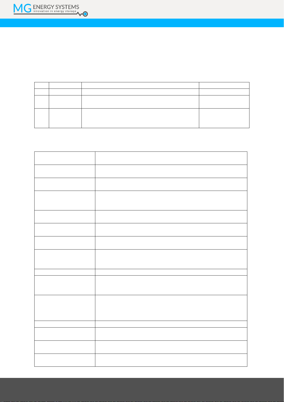
1.1 Document history
Table 1 - Document history
Rev.
Date
Changes
Revision author
2.0
13-01-2019
Initial document.
Mark Scholten
2.1
24-11-2020
Major changes: Text, images, added new chapters
etc.
Mark Scholten
2.2
11-01-2020
- Update schematic in Figure 1. Fixed minor typos.
- Removed image on page 27. This was not intended
to be there.
Mark Scholten
1.2 Terms, abbreviations, and definition
Table 2 - Terms, abbreviations, and definitions
Battery cell
Battery cell; the smallest building block in a battery, a chemical unit.
Cell is the bare Lithium-Ion battery cell.
Battery module
Battery module; is an assembly of submodules, BMS, fluid cooling
and outer enclosure.
Battery stack
Battery stack; is a set of multiple cells in cell cassettes constructed as
one.
BMS
Battery Management System; The BMS is the electronics that
monitors the battery cell parameters to keep it within the operation
specifications.
CAN-bus
Controller Area Network bus; CAN-bus is a standard serial data-bus
that provides data communication between two or more devices.
C-rate
C-Rate; the current (A) used to charge/discharge the battery system
divided by the rated ampere-hours (Ah).
EMS
Energy Management System; The EMS controls all power sources
and consumers in a system.
HVIL
High Voltage Interlock Loop; is a wire loop which is created for
protection of pulling cables from the battery system while in
operation. It shuts down the system when loop is not closed.
IC
Integrated Circuit; is a chip containing an electronics circuit;
MSDS
Material Safety Data Sheet; is a document that lists information
relating to occupational safety and health for the use of various
substances and products.
NMEA 2000
National Marine Electronics Association’s NMEA 2000 is a plug-and-
play communications standard used for connecting marine sensors
and display units within ships and boats, standardised in the IEC
61162-1.
PCB
Printed Circuit Board; is a board containing an electronic circuit;
PCBA
Printed Circuit Board Assembly; is a board containing an electronic
circuit including passive and active components;
SoC
State-of-Charge; is the remaining capacity in a battery cell or module
in percent (%).
SoH
State-of-Health; is a figure of merit of the condition of a battery (or a
cell, or a battery pack), compared to its ideal conditions.

MG Energy Systems B.V. | Foeke Sjoerdswei 3 | 8914 BH Leeuwarden | The Netherlands
Innovation in energy storage
MG Energy Systems B.V. | Foeke Sjoerdswei 3 | 8914 BH Leeuwarden | The Netherlands
Innovation in energy storage
2SAFETY INSTRUCTIONS
2.1 Safety message level definition
Table 3 - Safety message levels overview
WARNING:
A hazardous situation which, if not avoided, could result in death or serious injury.
CAUTION:
A hazardous situation which, if not avoided, could result in minor or moderate
injury.
LIMITATION:
A limitation to use which must be considered for safe use of the equipment.
ELECTRICAL HAZARD:
The possibility of electrical risks if instructions are not followed in a proper
manner.
NOTICE:
A potential situation which, if not avoided, could result in an undesirable
result or state.
A practice not related to personal injury.
2.2 User health and safety
General precautions
This product is designed and tested in accordance with international standards. The equipment should be
used according the intended use only.
WARNING:
A battery is a permanent energy source which cannot be turned off.
ELECTRICAL HAZARD:
Wear applicable personal protective equipment when working on a
battery system.
Use insulated tools when working on a battery system.
Make sure the locale health and safety regulations for working on battery
systems are followed.
There is a risk of electrocution and burns when working on higher voltage
systems without proper protective gear and special training.

MG Energy Systems B.V. | Foeke Sjoerdswei 3 | 8914 BH Leeuwarden | The Netherlands
Innovation in energy storage
Qualifications and training
The personnel responsible for the assembly, operation, inspection, and maintenance of the battery system
must be appropriately qualified. The user company must do the following tasks:
Define the responsibilities and competency of all personnel working on the battery system.
Provide instruction and training.
Ensure that the contents of the operating and safety instructions have been fully understood by the
personnel.
Check the local safety rules and guidelines they have higher preference over the manufacturers
specification in case of regulatory conflicts.
Working on higher voltages requires specific training and certification.
Instructions and training can be carried out by MG Energy Systems B.V. by order of the user company.
Non-compliance risks
Failure to comply with all safety precautions can result in the following conditions:
Death or serious injury due to electrical, mechanical, and chemical influences.
Environmental damage due to the leakage of dangerous materials.
Product damage.
Property damage.
Loss of all claims for damages.
Unacceptable modes of operation
The operational reliability of this product is only guaranteed when it is used as intended. The operating limits
on the identification tag and in the data sheet may not be exceeded under any circumstances. If the
identification tag is missing or worn, contact MG Energy Systems B.V. for specific instructions.
WARNING:
The battery modules may only be used in combination with a master BMS.
(MG Master LV or MG Master HV)
MG Energy Systems B.V. | Foeke Sjoerdswei 3 | 8914 BH Leeuwarden | The Netherlands
Innovation in energy storage
3TRANSPORT, STORAGE AND UNPACKING
3.1 Transport
The package and transport instructions provided by the manufacturer must be followed under all
circumstances.
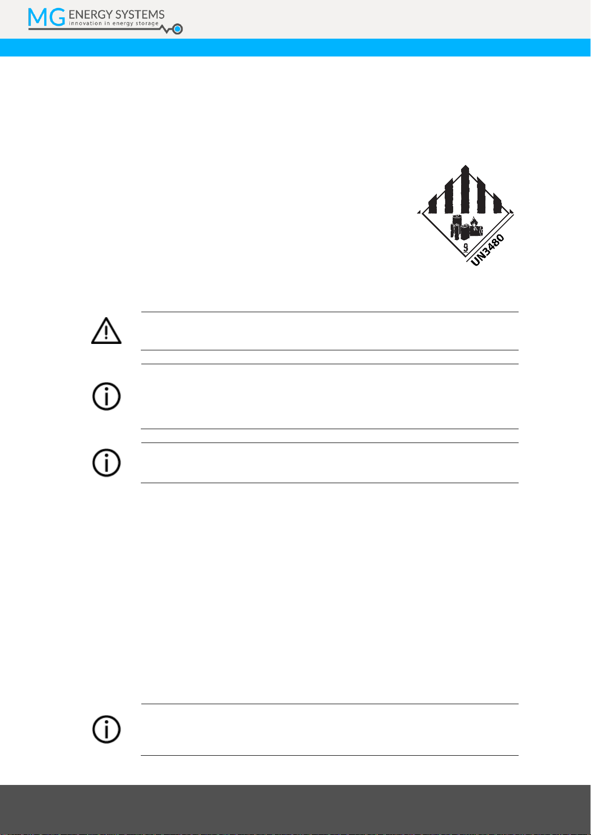
Notes on transport:
Use original packaging materials.
Lithium-Ion batteries are dangerous goods and must be
transported according to the applicable rules.
Transportation company and shipper must be qualified to
transport and package dangerous goods.
The SoC during transport must be ≤30%.
For details on transport of this battery module see the MSDS.
CAUTION:
It is not allowed to transport, connect or operate a damaged battery.
NOTICE:
No liability can be accepted for damage during transport if the equipment is not
transported in its original packaging or if the original packaging is opened before
the destination is reached.
NOTICE:
The SoC of the battery as delivered from factory is ≤30%.
3.2 Storage
The storage instructions provided by the manufacturer must be followed in all circumstances.
Notes on storage:
Battery module must be stored in its original packaging.
Store in a dry, clean, and conditioned location.
Local regulations for storage of dangerous goods may be applicable.
Recommended storage temperature of the battery module is between +10°C to +25°C.
It is recommended to limit the battery charge between 50% and 70% SoC. This will limit calendric
aging.
The battery module’s SoC is decreasing 1% per year. Recharging is required when the voltage is in the range
of the cut-off voltage.
NOTICE:
Check the MG Master LV or MG Master HV manual for storage of a connected
system.
MG Energy Systems B.V. | Foeke Sjoerdswei 3 | 8914 BH Leeuwarden | The Netherlands
Innovation in energy storage
NOTICE:
Check the voltage of the stored battery module every year.
When the battery module voltage is < 24 VDC, recharging is required. Contact MG
Energy Systems for specific instructions and tools.
3.3 Unpacking
Follow these handling guidelines when handling the product to prevent damage during unpacking:
Use care when handling the product.
Leave protective caps and covers on the product until installation.
CAUTION:
Always take the local applicable standards and regulations regarding the
prevention of accidents into account when handling the product. Be aware of the
total mass of the product and do not lift heavy objects unassisted.
Scope of delivery
The scope of delivery is as following:
MG HE battery module of type as described in chapter 5.
Quick instruction guide.
Top ingress protection cover HE Series (article number: MG4000267)
Replacement battery pole (dummy fuse).
NOTICE:
Not within the scope of delivery:
Power cables and connectors (details can be found in chapter 6.2.3).
Communication cables and connectors (details can be found in chapter
6.2).

MG Energy Systems B.V. | Foeke Sjoerdswei 3 | 8914 BH Leeuwarden | The Netherlands
Innovation in energy storage
4GENERAL DESCRIPTION
The HE battery series is based on a high energy density Lithium-Ion NMC battery cell. This means more
energy in less weight. The integrated battery management system brings the highest standard on safety and
gives insight in the status of the battery. Flexibility in system configuration is created by a modular design.
On a system level voltages up to 470 V and capacity up to 720 kWh can be created.
4.1 Battery system components
MG Energy Systems Lithium-Ion battery system consists of the following components:
One or more MG HE battery modules of the same type;
One or more MG Master HV or MG Master LV battery management systems; Details of these
battery management controllers can be found in their separate description documents;
4.2 Functional description
MG’s system philosophy is to have one master BMS, e.g. a MG Master LV or MG Master HV, per bank of
battery modules which communicates with one or more slave BMSs integrated in the Lithium-Ion battery
module(s). The slave BMSs are monitoring the battery cell parameters like cell voltage and cell temperature.
Besides monitoring, the slave BMS also controls balancing of cells based on the input of the master BMS.
All these parameters are send to the MG Master LV or MG Master HV via a dedicated CAN-bus which collects
all the data and monitors these parameters with different thresholds. When a parameter exceeds the
threshold this will first be communicated to the user via the, separated, auxiliary CAN-bus or the I/O
connections. If the exceeded threshold stays, the master BMS has the possibility to disconnect the batteries
from the system by opening the main contactors.
Functional and safety features of the MG LFP battery module are:
Superior energy density;
Modular design;
Plug and Play installation: Automatic configuration;
Low voltage solutions: 24 V up to 96 V;
High voltage solutions: Up to 460 V;
RJ45 or M12 CAN-Bus connector options;
MG Energy Systems B.V. | Foeke Sjoerdswei 3 | 8914 BH Leeuwarden | The Netherlands
Innovation in energy storage
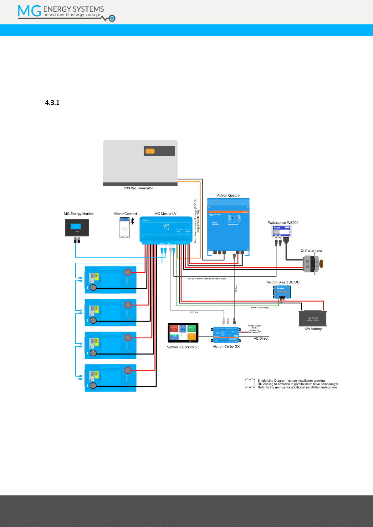
4.3 Example systems
Different kind of battery system configurations can be created because of the modular design. Battery
modules can be placed in series and parallel to create higher voltages and larger capacities.
Contact MG Energy Systems B.V. for more information about possible configurations.
Low voltage systems
Low voltage systems up to 96 VDC are setup with the MG Master LV series. For more information about the
MG Master LV, please refer to the data sheet and manual.
Figure 1 –Example 24 V Marine energy system
MG Energy Systems B.V. | Foeke Sjoerdswei 3 | 8914 BH Leeuwarden | The Netherlands
Innovation in energy storage
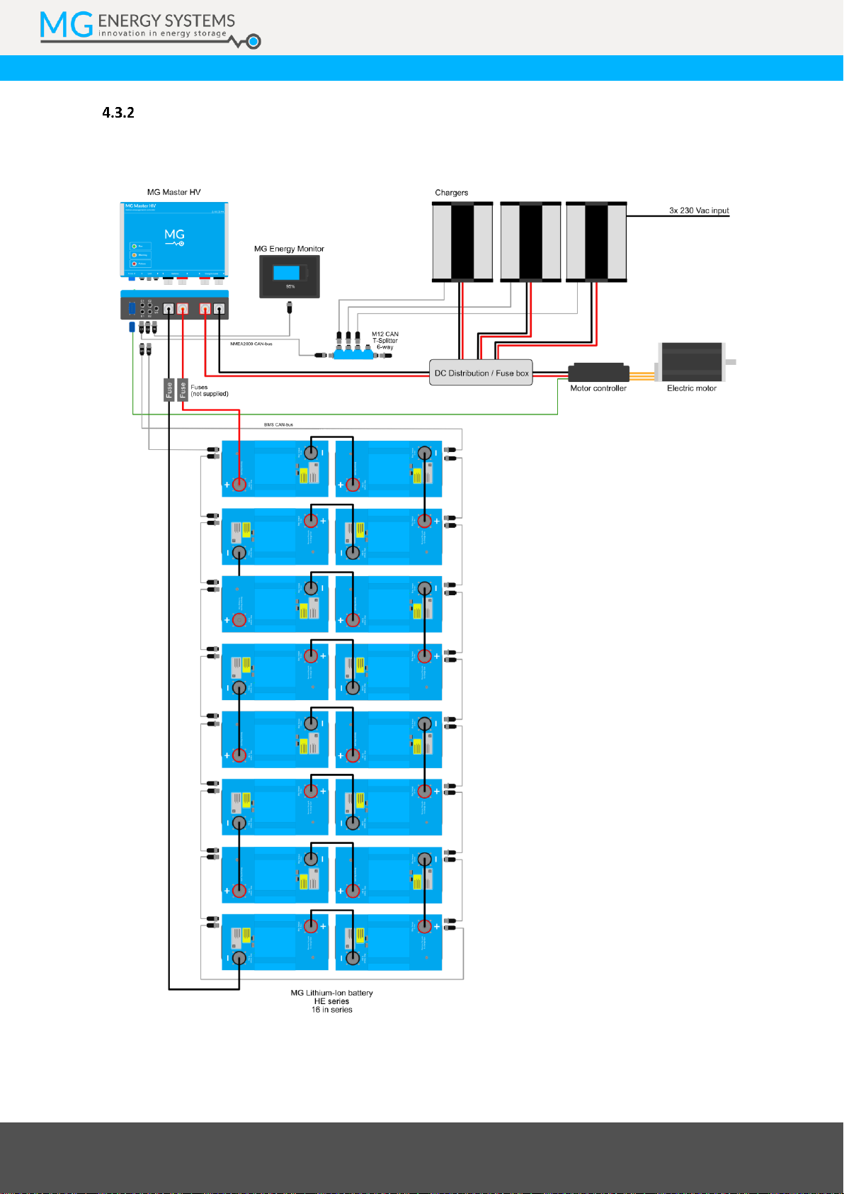
High voltage systems
High voltage systems up to 460 VDC are setup with the MG Master HV series. For more information about
the MG Master HV, please refer to the data sheet and manual.
Figure 2 –Example 460 VDC propulsion system
MG Energy Systems B.V. | Foeke Sjoerdswei 3 | 8914 BH Leeuwarden | The Netherlands
Innovation in energy storage
5MODELS
5.1 Models and configurations
Table 4, Table 5 and Table 6 lists the available battery module configurations. There is a difference between
system voltages and the CAN-Bus connector options.
RJ45 connectors and systems up to 96 V
Table 4 - Battery module configurations –RJ45 connectors and systems up to 96 V
Article number
MGHE240100
MGHE240150
MGHE240200
MGHE240300
Cell configuration
7S32P
7S48P
7S64P
7S96P
Nr. of cells
224
336
448
672
Nominal voltage
25.2 V
Capacity
100 Ah
150 Ah
200 Ah
300 Ah
Energy capacity
2.5 kWh
3.7 kWh
5.0 kWh
7.5 kWh
M12 connectors and systems up to 96 V
Table 5 - Battery module configurations –M12 connectors and systems up to 96 V
Article number
MGHE241100
MGHE241150
MGHE241200
MGHE241300
Cell configuration
7S32P
7S48P
7S64P
7S96P
Nr. of cells
224
336
448
672
Nominal voltage
25.2 V
Capacity
100 Ah
150 Ah
200 Ah
300 Ah
Energy capacity
2.5 kWh
3.7 kWh
5.0 kWh
7.5 kWh
M12 connectors and systems up to 460 V systems (M12, HV)
Table 6 - Battery module configurations –M12 connectors and systems up to 460 V systems
Article number
MGHE242100
MGHE242150
MGHE242200
MGHE242300
Cell configuration
7S32P
7S48P
7S64P
7S96P
Nr. of cells
224
336
448
672
Nominal voltage
25.2 V
Capacity
100 Ah
150 Ah
200 Ah
300 Ah
Energy capacity
2.5 kWh
3.7 kWh
5.0 kWh
7.5 kWh
MG Energy Systems B.V. | Foeke Sjoerdswei 3 | 8914 BH Leeuwarden | The Netherlands
Innovation in energy storage
Battery designation
As per IEC 62620 it is required to state a standard designation per battery module configuration. For the HE
series lithium-ion battery these are given in table 7.
Table 7 - Battery module designation as per IEC 62620
Article number
Designation
MGHE240100, MGHE241100, MGHE242100 (HE 100Ah)
INR/18/65/[32P7S]M/-20+55/95
MGHE240150, MGHE241150, MGHE242150 (HE 150Ah)
INR/18/65/[48P7S]M/-20+55/95
MGHE240200, MGHE241200, MGHE242200 (HE 200Ah)
INR/18/65/[64P7S]M/-20+55/95
MGHE240300, MGHE241300, MGHE242300 (HE 300Ah)
INR/18/65/[96P7S]M/-20+55/95
MG Energy Systems B.V. | Foeke Sjoerdswei 3 | 8914 BH Leeuwarden | The Netherlands
Innovation in energy storage
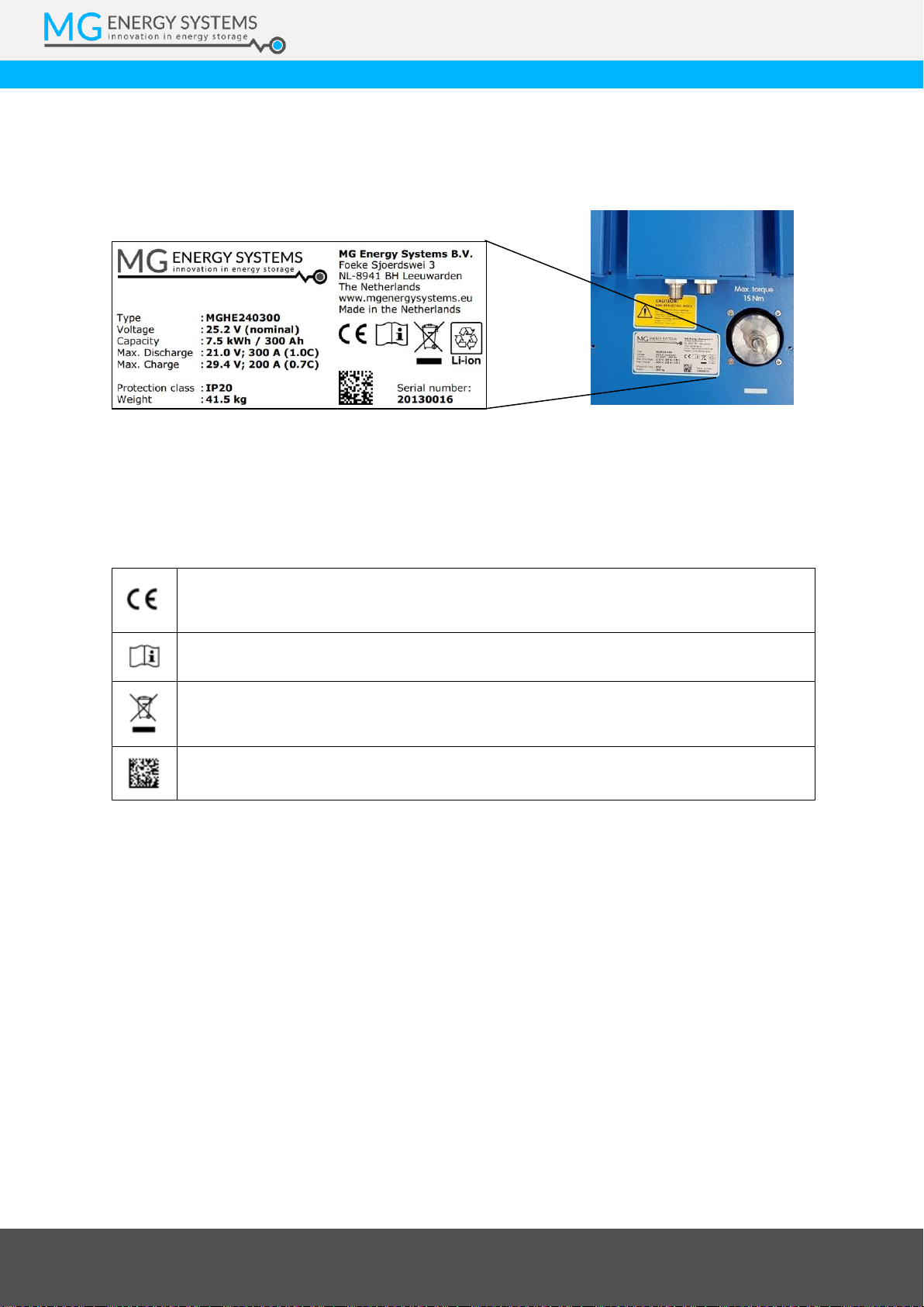
5.2 Identification label
The identification label of the MG HE battery module is located at the top of the enclosure under the lid.
Example identification label:
Figure 3 - Example identifications label
The identifications label shown in figure 3 contains written information about the product. The explanation
of the symbols used on the identification label is stated in table 8.
Table 8 - Identification lable logo explaination
Declaration of conformity with health, safety, and environmental protection standards
for products sold within the European Economic Area as per directive 2014/35/EU.
Symbol indication the manual must be red before installation and use of the device.
Device is treated according the Waste Electrical and Electronic Equipment (WEEE)
Directive 2012/19/EU.
GS1 data matrix type barcode containing detailed product information.
MG Energy Systems B.V. | Foeke Sjoerdswei 3 | 8914 BH Leeuwarden | The Netherlands
Innovation in energy storage
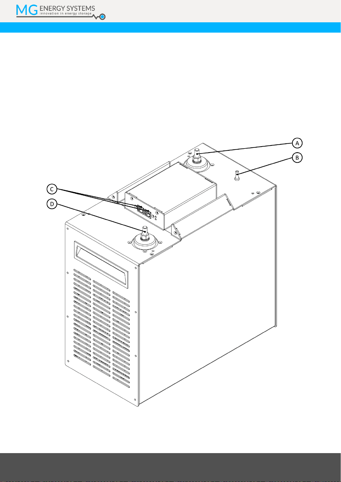
6OVERVIEW
This chapter shows an overview of the HE battery.
Each battery module contains the following common parts:
Negative battery pole connection;
Positive battery pole connection;
BMS CAN-bus connection, either RJ45 or M12;
Status LEDs;
6.1 Connection overview
Figure 4 –HE 200 Ah module overview

MG Energy Systems B.V. | Foeke Sjoerdswei 3 | 8914 BH Leeuwarden | The Netherlands
Innovation in energy storage
Table 9 - Module connection overview
Part
Description
A
Positive power connection (including fuse). M8 bolt connection.
B
Equipotential bonding connection (only available on the (M12, HV) option).
C
CAN-Bus communication, either RJ45 or M12.
D
Negative power connection. M8 bolt connection.
E
Cooling fans (not for HE 300Ah)

This manual suits for next models
11
Table of contents
Other MG Energy Systems Camera Accessories manuals


