EM-2399 Rev.3 P. 1 / 5
MG CO., LTD. www.mgco.jp
5-2-55 Minamitsumori, Nishinari-ku, Osaka 557-0063 JAPAN
INSTRUCTION MANUAL
PATLABOR™
DISCRETE INPUT TOWER LIGHT
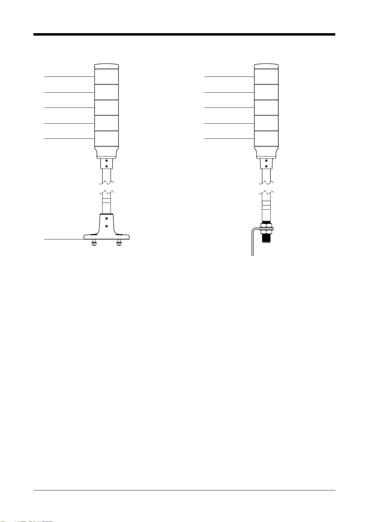
(super-small size, 50 mm dia., 1 - 5 layers, pole mounting) MODEL IT50SA3
BEFORE USE ....
Thank you for choosing us. Before use, check the contents of
the package you received as outlined below.
If you have any problems or questions with the product,
please contact our sales office or representatives.
This product is for use in general industrial environments,
therefore may not be suitable for applications which require
higher level of safety (e.g. safety or accident prevention sys-
tems) or of reliability (e.g. vehicle control or combustion con-
trol systems).
For safety, installation and maintenance of this product
must be conducted by qualified personnel.
■PACKAGE INCLUDES:
Tower Light .........................................................................(1)
Mounting fixtures*
M5 screw ..........................................................................(4)
Plain washer ....................................................................(4)
Spring washer..................................................................(4)
Nut ...................................................................................(4)
* Provided only for the circular base mount type.
■MODEL NO.
Confirm Model No. marking on the product to be exactly
what you ordered.
■INSTRUCTION MANUAL
This manual describes necessary points of caution when
you use this product, including installation, connection and
basic maintenance procedures.
POINTS OF CAUTION
■CONFORMITY WITH EU DIRECTIVES
• Altitude up to 2000 meters.
• The actual installation environments such as panel con-
figurations, connected devices, connected wires, may af-
fect the protection level of this unit when it is integrated
in a panel system. The user may have to review the CE
requirements in regard to the whole system and employ
additional protective measures to ensure the CE conform-
ity.
• The equipment is intended to be installed in an industrial
environment defined by EN 60947-5-1.
■POWER INPUT RATING & OPERATIONAL RANGE
• Locate the power input rating marked on the product and
confirm its operational range as indicated below:
24 V AC rating: 24 V ±10%, 47 − 66 Hz, ≤ 2.4 VA
24 V DC rating: 24 V ±10%, ≤ 2.2 W
• Supplying any level of power other than specified above
can damage the unit or the power source.
• Power up characteristics of a power supply for the unit
must be such a way that the output voltage goes up with-
in operational voltage range of the unit in 5 seconds.
■GENERAL PRECAUTIONS
• Before you remove the unit or mount it, turn off the power
supply and input signal for safety.
• The unit must not be subjected to external force.
• Do not rub the unit with organic solvent like paint thin-
ner.
• Do not block the unit’s ventilation openings or use it in
areas where heat accumulates.
Additionally, do not store or use it under high-tempera-
ture conditions.
• Do not use the unit in an environment where flammable
gases are present. This may result in an explosion.
• Do not disassemble or modify the unit in any way. Doing
so may result in a fire or an electrical shock.
• Do not store or use the unit in locations subject to direct
sunlight, or where excessive dust or dirt is present.
• The unit is a precision equipment. Do not store or use it
where large shocks or excessive vibration can occur.
• Observe the environmental conditions when using the
unit.
■ENVIRONMENT
• Indoor use.
• Do not install the unit where it is subjected to continuous
vibration. Do not subject the unit to physical impact.
• Environmental temperature must be within -10 to +55°C
(14 to 131°F) with relative humidity within 30 to 90% RH
in order to ensure adequate life span and operation.
• Mount the unit on a foundation of sufficient strength.
• Recommended bolt/nut tightening torque:
M3: 0.3 − 0.4 N·m
M5: 1.4 − 1.6 N·m
M8: 6.1 − 6.3 N·m
M17: 24 − 26 N·m
• L-shaped bracket
The L-shaped bracket is only loosely fit. Tighten its M17
nut securely when the position is determined.
■INGRESS PROTECTION
Circular base mount type
• Degree of protection: IP65
• The IP code is conformable when the unit is mounted ver-
tically. The bottom of the pole is not protected.
• In order to prevent ingress of water or dust through the
bottom of the pole, mount the unit on a flat plane, and be
sure that the gasket on the bottom of the pole does not roll
back or dust is not on the gasket.
L-shaped mount type
• Degree of protection: IP13
• The IP code is conformable when the unit is mounted ver-
tically.
■WIRING
• Do not install cables close to noise sources (relay drive
cable, high frequency line, etc.).
• Do not bind these cables together with those in which
noises are present. Do not install them in the same duct.