manuals.online logo
Brands
  1. Home
  2. •
  3. Brands
  4. •
  5. MGS
  6. •
  7. Plumbing Product
  8. •
  9. MGS CB432 N User manual

MGS CB432 N User manual

ASSEMBLY INSTRUCTIONS THERMOSTATIC SHOWER CB432N
•Remove various parts from the carton with extreme care.
Disassemble handle in 5 parts: Handle Body (E) –Knob (G) –Cover (H) –CAM (F) –Ring (B)
proceeding as follows:
- unscrew Cover (H) using 3 pin tool here enclosed.
- remove handle center screw.
•Check on the wall that the built-in thermostatic valve is clean and that installation has been made
correctly according to our separate pre-assembly instructions. In particular, check that the level
pine indicated on the plastic protection lid is positioned +/-8 mm with respect to the finish wall
level (FIG 1) and that the shower finishing plate covers wall recessed area.
•At this point remove (by unscrewing) plastic protection lid from the valve body and the two
protection covers from the nozzle on the right.
IMPORTANT: make sure that the valve is closed by fully turning its plastic body clockwise.
ASSEMBLY OF MAIN HANDLE WITH THERMOSTATIC CONTROL
(FIG 2)
•Place finishing plate (A) on valve body (B1) and on nozzles (C1e D1) pushing it against the wall.
•Fully screw ring (B) to body (B1) keeping knurled area on the outside which will block the ring
to the finishing plate.
•Fully screw sleeve (C3) to nozzle (C1), the nozzle’s thread must be outside the covering.
•Push ring (C2) on the sleeve (C3) against the finishing plate (the ring’s lower diameter must enter
the plate’s hole).
•Push hand shower hook (D2) on the nozzle (D1) against the finishing plate and tighten two grub
screws with allen key attached.
(FIG 3)
•Push handle (E) on the valve by keeping lever in vertical position (valve is closed).
ATTENTION: Check that the handle is fully pushed in.
(FIG 4)
Insert cam (F) on the large broach of the valve and block to the handle with the 3 allen screws M4
as per (FIG 4A).
(FIG 5)
-Place knob (G) on the valve’s central shaft and rotate until the 3 pins appear through the holes.
-Tighten firmly with screw M4 after positioning washer (R).
-Close by screwing cover (H) on the handle through 3 pin tool to be conserved for future
maintenance.
CHANGING WATER TEMPERATURE AT STOP POSITION
Cam (F) in default position (FIG 4A) determines with an anticlockwise rotation of the knob, a stop
point corresponding to a comfortable warm water temperature. To increase water temperature pull
the knurled ring of the knob and continue anticlockwise rotation. By inverting to clockwise
rotation the stop point will fall back into position.
To change temperature stop point, remove knob (G) (FIG 5), loosen 3 Allen screws (FIG 4a) and
change position of cam (F) (FIG 4). Rotate towards left for warmer water and towards right for
colder water.
ASSEMBLY OF SHOWER DIVERTER BLOCK
(FIG 6)
•Fully push diverter block (I) into parts (C1, C2and C3) taking care of not damaging O-Ring
gaskets.
•Hand tighten the assembly through knurledrings (I1, I2and I3) by closing then progressively and
alternatively.
CONNECTION OF HAND SHOWER
(FIG 7)
•Screw hose (L) to outlet (D2) after placing gasket (M).
•Cover hose end (L) with trim cover (N) and tighten grub screw (O) with allen key attached.

Other MGS Plumbing Product manuals

MGS SPIN D Maintenance and service guide

MGS

MGS SPIN D Maintenance and service guide

MGS SPIN D User manual

MGS

MGS SPIN D User manual

MGS 7306-N-600 User manual

MGS

MGS 7306-N-600 User manual

MGS CB404 User manual

MGS

MGS CB404 User manual

MGS Spin HC Maintenance and service guide

MGS

MGS Spin HC Maintenance and service guide

Popular Plumbing Product manuals by other brands

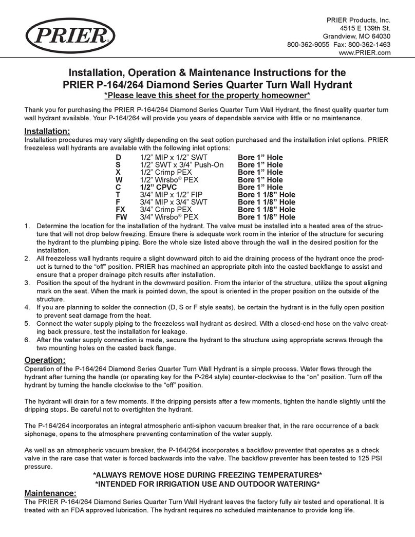
Prier P-164/264 Installation, operation & maintenance instructions

Prier

Prier P-164/264 Installation, operation & maintenance instructions

Franke 2030005623 Installation and operating instructions

Franke

Franke 2030005623 Installation and operating instructions

Glacier bay 67190W-6104 Installation and care guide

Glacier bay

Glacier bay 67190W-6104 Installation and care guide

Kernau KSS U 61.1 1B SS manual

Kernau

Kernau KSS U 61.1 1B SS manual

Signature Hardware LEXIA 953768 quick start guide

Signature Hardware

Signature Hardware LEXIA 953768 quick start guide

Delabie BIOSAFE quick start guide

Delabie

Delabie BIOSAFE quick start guide

Hans Grohe Croma 280 Air 1jet EcoSmart 26221007 Instructions for use

Hans Grohe

Hans Grohe Croma 280 Air 1jet EcoSmart 26221007 Instructions for use

F.lli Frattini 98011 installation instructions

F.lli Frattini

F.lli Frattini 98011 installation instructions

Sloan Wes-115 installation instructions

Sloan

Sloan Wes-115 installation instructions

CIFIAL 3215005 Assembly and instruction manual

CIFIAL

CIFIAL 3215005 Assembly and instruction manual

American Standard 6074F installation instructions

American Standard

American Standard 6074F installation instructions

Sanela SLUN 36A Mounting instructions

Sanela

Sanela SLUN 36A Mounting instructions

ZURN PEX installation guide

ZURN

ZURN PEX installation guide

Speakman S-8700 Installation, maintenance and operation instructions

Speakman

Speakman S-8700 Installation, maintenance and operation instructions

Toto TBV03429B installation manual

Toto

Toto TBV03429B installation manual

Spectrum Brands Pfister Marielle 46 Series manual

Spectrum Brands

Spectrum Brands Pfister Marielle 46 Series manual

Hans Grohe Axor Carlton 17133 1 Series Installation/Warranty

Hans Grohe

Hans Grohe Axor Carlton 17133 1 Series Installation/Warranty

Crosswater US-BSW0101 installation instructions

Crosswater

Crosswater US-BSW0101 installation instructions

manuals.online logo
manuals.online logoBrands
  • About & Mission
  • Contact us
  • Privacy Policy
  • Terms and Conditions

Copyright 2025 Manuals.Online. All Rights Reserved.