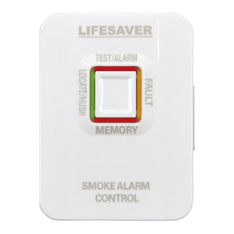
PSA LIFESAVER 6000THL User manual

11
Smoke Alarm Remote Control
User Guide
MODEL 6000THL
TEST/ALARM
MEMORY
SMOKE ALARM
CONTROL
FA U LT
LOCATE/HUSH

2
Contents
1. Introduction ......................................................... 4
2. Technical Specification ...................................... 6
3. Installation .......................................................... 7
4. Programming the Network...................................9
5. Operation............................................................11
6. Remote Status and
Visual Indicators Table ......................................13
7. Troubleshooting Table .......................................15
8. Service and Warranty .......................................16
9. Warranty Registration....................................... 18
Quick Setup for New Wireless Network
............................................................................... 19

23
Thank you for purchasing this PSA Lifesaver
Smoke Alarm Remote Control
NOTE: Please thoroughly read this User Guide and
save the document for future reference and to pass
on to any subsequent owner.
Important: Please read this user guide before
installation.

4
1. Introduction:
The Smoke Alarm Remote Control model
6000THL allows compatible Lifesaver Smoke
Alarms to be conveniently tested, hushed and
located. It has a memory feature and status
indication. This controller is wireless and will
provide home owners with a more convenient
method to identify which smoke alarm has
activated, easily silence alarms and also promote
regular testing of smoke alarms. The Smoke
Alarm Remote Control will only control compatible
240VAC mains powered smoke alarm models that
are mounted on the 6000WB Wireless Base.
Important: Only compatible smoke alarms will
operate with the remote control. Failing to use the
correct smoke alarm and accessories may render
the system inoperable.
One Smoke Alarm Remote Control can operate
up to 23 smoke alarms on a wireless system.
Compatible: Models
Smoke Alarm 6000DCW, 6000, 6000RL,
6000W, 6000RLW
Wireless Base 6000WB

45
The wireless signal uses radio frequency to
create an interlinked network of smoke alarms.
When one smoke alarm activates, it will trigger
other smoke alarms within the same wireless
network. The Smoke Alarm Remote Control will
test, hush and locate smoke alarms within the
same wireless network.
Feature:
TEST/ALARM
MEMORY
SMOKE ALARM
CONTROL
FA U LT
LOCATE/HUSH
Front
LED
Button
(TEST/LOCATE/
HUSH/MEMORY)
- Test/Alarm(Red),
- Fault(Amber),
- Memory(Red),
- Locate/Hush(Green)
(OFF/ ON)
Switch
Bracket holder
Back

6
2. Technical Specification
Power: Lithium 10 year battery
Radio Frequency: 918 MHz
Wireless Range: 100 meters open air. 30m indoors.
Operation: Up to 23 units
Temperature: 0°C– 40°C
Humidity: 0 – 93% (non-condensing)
Service Life: 10 years from installation
Approval: AS/NZS 4268:2017
AS/NZS 3786:2014 (Selected Clause)
AS/NZS CISPR 32:2015
AS/NZS 62368.1:2018
AS/NZS 2772.2:2016 AMD 1:2018
This product has an expected service life of 10 years
under normal conditions. We recommend that you
should replace the product after 10 years from
installation date to ensure normal operation.

67
3. Installation
The Remote Control can be mounted either on a
wall bracket, or directly on the wall.
a. To mount the Remote Control directly on the
wall.
1. Remove the back cover of the remote
using a small flat blade screwdriver at the
bottom of the Remote Control.
2. Fix the back cover on the wall using screws
provided.
3. Fit the Remote Control back into its back
cover.
Close
Close
(1)
(2) (3)

8
Slide down
Side Wall
b. Mounting Bracket.
The Remote Control can be mounted onto a wall
bracket. Mount the remote bracket on the wall,
then slide the Smoke Alarm Remote Control into
the bracket.

89
4. Programming the Network
Before using the Remote Control, the unit needs to
be programmed to an existing wireless network of
smoke alarms.
4.1 Definitions:
OOB: Out Of Box. Factory Default status. When first turned
ON, an OOB device will auto-search and join an existing
wireless network.
Standby: Normal mode, connected to a wireless network.
Stand alone: Not connected to a network. Stand alone
mode.
4.2 New Wireless Network Setup
If you are joining this Remote Control at the same
time as other new wireless smoke alarms, then follow
the setup procedure in the wireless smoke alarm
User Guide as well.
1. First, create or open a wireless network of smoke
alarms before joining the smoke alarm control.
2. Slide the power switch (at the back of the Remote)
to ON position. The Remote will automatically
search for a wireless network; its red LED will flash
ON and OFF every alternate second.
When the Remote has successfully joined a
wireless network, its LEDs will light up in a rotating
sequence.
3. Close the network on the smoke alarms by press-
ing 6000THL or 6000DCW or 6000WB button
2 times. And then all RF devices will go into stand-

10
by mode. The network will also timeout after 15 min-
utes and automatically close. But if it didn’t connect
to any network after 15 minutes, the Smoke Alarm
Remote Control will go into Stand Alone mode and
the Green LED will flash twice every 30 seconds.
NOTE: It is recommended to first create the wireless
smoke alarm network. Then use the Push To Test
(PTT) to confirm it is working properly (See wireless
smoke alarm User Guide). And then join this Remote
as an additional device in the wireless network.
NOTE: The 6000THL Remote Control cannot be set as
a Coordinator.
4.3 Smoke Alarm Remote Control Network Setting
Reset network: To clear the wireless network settings
in the Remote Control, open the network by pressing
its button 4 times. Then press and hold the button for
8 seconds. Release the button immediately when the
Red LED flashes rapidly. After the Remote is reset, the
unit will go to Stand Alone mode.
Stand Alone mode to Network Search mode: Press
the 6000THL button twice to change from Stand-Alone
mode to Network Joining mode.
Open a network: When the Remote is in Standby
mode, press the button 4 times to open the wireless
network.
View the number of network devices: Press and re-
lease the Remote Control button when the network is
in open mode to view the number of network devices.
The number of Red LED flashes denote the number of
wireless devices.
Close a network: Press the corresponding button
twice on any interconnected wireless device to close
the network.

10 11
5. Operation
Test Function
Press and release the Button, the Red LED will start
flashing. All the interconnected smoke alarms in the
wireless network will sound.
Allow up to 20 seconds for the interconnected smoke
alarms to respond to this Test function.
Low Battery HUSH
If a smoke alarm is in low battery condition, the low
battery beeping can be hushed for 8-24 hours.
This feature will allow the user to attend to the smoke
alarm at a more convenient time.
Test Fault
If the smoke alarm network fails to respond to the
Test function, the amber Fault LED of the Remote
Control will flash seven times in 2-cycles to indicate
Test Fault.

12
Locate and Hush Function
While the smoke alarms are sounding, the Locate
function will identify the initiating smoke alarm. Press
and release the Button to silence all interconnected
smoke alarms for 2 minutes. However, the initiating
smoke alarm will continue to sound. The green LED
on the Remote Control will flash once every two
seconds. Locate mode will automatically timeout after
2 minutes; or if the smoke has cleared.
Press and release the Button again to hush the
initiating smoke alarm. The green LED of the Remote
Control will flash 4 times quickly and then extinguish.
The Hush mode will auto-exit after 9-10 minutes.
• Important: To Hush the smoke alarms, the
initiating smoke alarm must first be located.
Alarm Memory
The LifeSaver 6000-series Smoke Alarms have an
Alarm Memory function. This function indicates if a
smoke alarm had sounded in the past 24-hour period.
The Memory red LED will flash 3-times every 40 sec-
onds, if there has been an Alarm Memory event. To
identify which smoke alarm had sounded, press the
Button and the corresponding smoke alarm will chirp.
Press the button again to exit Alarm Memory mode.
This mode will also auto exit in 3 minutes.
It is recommended to test the alarms and remote
control monthly.

12 13
6. Remote Control Status and Visual Indicators
Status Visual
Indicators
Description
or Action:
Network
Search
Red LED (top)
ashes 1 sec On & 1
sec Off
Remote Control
searching for an opened
wireless network to join.
Stand-alone Green LED ashes
twice every
30 sec.
Not connected to any
network. Press button
twice to start searching
for a network to join.
Stand By Green LED ashes
once every 60 sec.
Normal operating mode.
Remote Control on
Standby, waiting for user
action.
Network found
& device joined
as RFD
LEDs ash in
circular pattern
(Red→Green→Red
→Amber→Blue.)
Remote Control joined
successfully to wireless
network.
Reset Device
(during join
mode)
Red LED flashes
rapidly; then Off
Press and hold the button
for 8 seconds. Release
the button immediately
when Red LED ashes
rapidly. After the Remote
is reset, the unit will go
into Stand Alone mode.
Open a
network
LEDs ash in
circular pattern
(Red→Green→Red
→Amber→Blue).
Network has been
opened. To open the
network, press button 4
times while in Standby
mode.
Close a
network
All LEDs stop
flashing.
To close the network,
press button twice while
network is open.

14
Status Visual
Indicators
Description
or Action:
View the
number of
network
devices
Top red LED ash the
number of network
devices
Press & release button
while network is open
Test
Red LED ashes 6
times repeatedly (in
two groups of three
ashes).
In Standby mode, press &
release Button to initiate Test
mode. All interconnected
smoke alarms will sound
within 20 seconds.
Alarm
(smoke)
Red LED ashes 6
times repeatedly (in
two groups of three
ashes).
When the network is in alarm
condition.
Locate Green LED ashes once
every 2 sec
Press the button to locate the
initiating smoke alarm while
the system is in alarm. Auto
cancels after 2 minutes, or if
alarm event has cleared.
HUSH Green LED ashes 4
times quickly, then Off.
During alarm locate, press
the button again to silence the
alarms for 9-10 minutes.
Smoke
Alarm
Memory
Red LEDs (“Memory”
on Remote Control and
also initiating smoke
alarm) ash 3 times
every 40 sec
NOTE: Alarm memory is
only retained for 24 hrs.
Alarm
Memory
Locate
Red LEDs ash quickly.
(“Memory” on Remote
Control and also initiat-
ing smoke alarm).
Press the Button to locate the
initiating smoke alarm. Press
button again to exit. Or will
auto timeout in 3 minutes.

14 15
7. Troubleshooting Table
Status Visual Indicators Description or Action
Not Joined Green LED ashes
twice every 30 sec
Standalone mode.
Press the button twice to
open the network to join
the Remote Control.
Low Battery Amber LED ashes
every 30 sec
Battery Voltage is low.
Please dispose of
the remote control
and replace with a
new one.
Drop out
network
Amber LED ashes
every 2 sec
Loss of network
connection. Perform
Power Reset by
turning Off the rear
switch and then On
again. Then press
Button 4 times to start
searching for network
to join.

16
8. Service and Warranty
If after reviewing this manual you feel that your product
is defective in any way, do not tamper with the unit.
Return it for servicing to: PSA Products Pty Ltd of 17
Millicent Street, Burwood Victoria 3125 (See Warranty
for in-warranty returns).
1. PSA Products Pty Ltd (ABN: 99 076 468 703) of 17
Millicent Street, Burwood 3125 Victoria, Australia
warrants this product for a period of two (2) years
from the date of purchase, as reflected on the
Authorized Reseller’s or Distributorʼs invoice /
receipt provided to you. PSA Products Pty Ltd will
repair or replace the product (at the option of PSA
Products) due to any manufacturing defect, at the
cost of PSA Products Pty Ltd (excluding any lab our
costs relating to removal or re installation of product,
and transport costs).
2. This warranty shall not apply to the product if it has
been damaged, modified, abused or altered after
the date of purchase, or if it fails to operate due to
improper maintenance.
3. To the extent permitted by law, the liability of PSA
Products Pty Ltd arising from the sale or under the
terms of this limited warranty shall not in any case
exceed the cost of replacement and subject to this
clause. In no case shall PSA Products Pty Ltd be
liable for consequential loss or damages resulting

16 17
from the failure of the product or breach of this,
or: Any other warranty, express or implied, loss or
damage caused by failure to abide by the
instructions supplied in the leaflets.
4. To the extent permitted by law, PSA Products Pty
Ltd., makes no warranty, expressed or implied,
written or oral, including that of merchantability or
fitness for any particular purpose, with respect to
the consumer replaceable battery if any. A product
with non-serviceable built-in battery is covered
under warranty of the product.
5. This warranty is provided in addition to other rights
and remedies you have under law: Our goods
come with guarantees that cannot be excluded
under the Australian Consumer Law. You are
entitled to a replacement or refund for a major
failure and compensation for any other reasonably
foreseeable loss or damage. You are also entitled
to have the goods repaired or replaced if the goods
fail to be of acceptable quality and the failure does
not amount to a major failure. What constitutes a
major failure is set out in the Australian Consumer
Law.

18
9. Warranty Registration
Register this product for warranty to ensure fast and
efficient service. Please visit our website https://www.
psaproducts.com.au/register-product/ to register.
It is important to register your product. It will ensure
your investment is protected in case it is damaged or
broken and we can effectively carry out any warranty
claims. Registration will also allow us to contact you
in an unlikely event of product safety notification
required under Consumer Product Safety Act.
Registration will also help us improve our product
design to meet your needs.
Another Quality Product By:
PSA Products Pty Ltd
17 Millicent Street, Burwood, Victoria 3125, Australia
Ph: (03) 9888 9889
Email:enquiry@psaproducts.com.au
Website:www.psaproducts.com.au
P/N: 1208-7206-00

18 19
Step 1. Refer to the smoke alarm wireless setup.
NOTE: It is recommended to create the wireless
smoke alarm network first and do Push to test (PTT)
to confirm it works properly. Then join the Smoke Alarm
Remote Control as an additional device in the wireless
network.
Please Note: The smoke alarm controller will only
operate on smoke alarms with wireless RF interlink.
Quick Setup for New Wireless Network
Step 2. Open wireless network on the smoke alarms.
Refer to smoke alarm user guide.
Quick Setup for New Wireless Network
Step 3. Slide power switch to ON position at the back of
remote.
Quick Setup for New Wireless Network
Close the wireless network by pressing the
Remote Control button twice
Quick Setup for New Wireless Network
The remote will search network automatically
with red LED flash 1 second ON and 1 second OFF.
1
Slide power switch to ON position
When the Remote Control has successfully joined
the network, its LEDs will flash in a circular
pattern (RED →Green →Red →Amber →Blue).
2
The Remote Control has joined successfully
3
(OFF/ ON)
Switch
Back
TEST/ALARM
MEMORY
SMOKE ALARM
CONTROL
FAU LT
LOCATE/HUSH
TEST/ALARM
MEMORY
SMOKEALARM
CONTROL
FAULT
LOCATE/HUSH
CEILING
WALL
Please read through 6000WB, 6000DCW
for Interlink Network Setup.
Refer to 6000DCW and 6000WB user guide to
open the wireless network.
Quick Start Guide
6000DCW Interlink
Network Setup
Please Read All Instructions First!
1
2
0
8
-
7
2
0
9
-
0
0
Quick Start Guide
6000WB Interlink
Network Setup
Please Read All Instructions First!
TEST/ALARM
MEMORY
SMOKE ALARM
CONTROL
FA U LT
LOCATE/HUSH
Close
the wireless network.

20
Step 1. Refer to the smoke alarm wireless setup.
NOTE: It is recommended to create the wireless
smoke alarm network first and do Push to test (PTT)
to confirm it works properly. Then join the Smoke Alarm
Remote Control as an additional device in the wireless
network.
Please Note: The smoke alarm controller will only
operate on smoke alarms with wireless RF interlink.
Quick Setup for New Wireless Network
Step 2. Open wireless network on the smoke alarms.
Refer to smoke alarm user guide.
Quick Setup for New Wireless Network
Step 3. Slide power switch to ON position at the back of
remote.
Quick Setup for New Wireless Network
Close the wireless network by pressing the
Remote Control button twice
Quick Setup for New Wireless Network
The remote will search network automatically
with red LED flash 1 second ON and 1 second OFF.
1
Slide power switch to ON position
When the Remote Control has successfully joined
the network, its LEDs will flash in a circular
pattern (RED →Green →Red →Amber →Blue).
2
The Remote Control has joined successfully
3
(OFF/ ON)
Switch
Back
TEST/ALARM
MEMORY
SMOKE ALARM
CONTROL
FAU LT
LOCATE/HUSH
TEST/ALARM
MEMORY
SMOKEALARM
CONTROL
FAULT
LOCATE/HUSH
CEILING
WALL
Please read through 6000WB, 6000DCW
for Interlink Network Setup.
Refer to 6000DCW and 6000WB user guide to
open the wireless network.
Quick Start Guide
6000DCW Interlink
Network Setup
Please Read All Instructions First!
1
2
0
8
-
7
2
0
9
-
0
0
Quick Start Guide
6000WB Interlink
Network Setup
Please Read All Instructions First!
TEST/ALARM
MEMORY
SMOKE ALARM
CONTROL
FA U LT
LOCATE/HUSH
Close
the wireless network.
Table of contents
Other PSA Remote Control manuals
Popular Remote Control manuals by other brands
Scolmore
Scolmore ClickSmart RF Pilot installation manual
IMMAX
IMMAX NEO Smart remote v2 Zigbee 3.0 user manual
Philips
Philips SBCRU610 Specifications
EcoxGear
EcoxGear SOUNDEXTREME SEI-SETXLED user guide
Armour Home Electronics
Armour Home Electronics Systemline LRN7 user guide
MINN KOTA
MINN KOTA MICRO REMOTE owner's manual
