MHS Boilers XenoROL XR40 Instruction manual

INSTALLATION,OPERATION,
MAINTENANCE MANUAL
XenoROL®
XR40 and XR48
P/N: 90480006
Revision Date: October 1, 2021

XENOROL® IOM
P/N: 90480006 Rev Date: 10/01/2021 Page 2of 161
TABLE OF CONTENTS
1 IOM INTRODUCTION............................................................................................................................................................... 6
2 MHS CONVEYOR POLICIES .................................................................................................................................................... 7
2.1 MHS CONVEYOR RECOMMENDS PROPER LABELS FOR CONVEYOR TYPES..................................................................................... 9
2.2 WARNINGS AND SAFETY INSTRUCTIONS.....................................................................................................................................10
2.2.1 Warnings and Safety Instructions .............................................................................................................................11
2.3 MHS CONVEYOR CONTROLS SAFETY GUIDELINES......................................................................................................................13
3 INTRODUCTION TO XENOROL®............................................................................................................................................ 15
3.1 DEFINITION OF TERMS ..............................................................................................................................................................16
4 CAPACITY OF ROLLERS AND FRAMES ............................................................................................................................... 18
4.1 ROLLER ...................................................................................................................................................................................18
4.2 FRAME.....................................................................................................................................................................................18
4.3 MINIMUM PRESSURE ACCUMULATION .......................................................................................................................................19
5 RECEIVING & SITE PREPARATION ...................................................................................................................................... 20
5.1 GENERAL .................................................................................................................................................................................20
5.2 PART INVENTORY &IDENTIFICATION..........................................................................................................................................21
5.3 TYPICAL XENOROL®LOOSE PARTS ..........................................................................................................................................23
5.4 LINE-SHAFT EXTRA O-RINGS .....................................................................................................................................................24
6 INSTALLATION DETAILS....................................................................................................................................................... 25
6.1 GENERAL PROCEDURES............................................................................................................................................................25
6.2 DIMENSIONAL REFERENCE POINTS............................................................................................................................................25
6.3 ELEVATIONS .............................................................................................................................................................................26
6.4 DESCRIPTION OF OPERATION ....................................................................................................................................................28
6.5 TYPICAL LAYOUT /LEGEND.......................................................................................................................................................31
6.6 30° SPUR DIMENSIONS...........................................................................................................................................................33
6.7 45° SPUR DIMENSIONS...........................................................................................................................................................34
6.8 GEAR MOTOR ACTIVATION ........................................................................................................................................................35
7 SUPPORTING ARRANGEMENTS.......................................................................................................................................... 37
7.1 SUPPORTS &CONNECTIONS .....................................................................................................................................................37
7.2 FLOOR SUPPORTS ....................................................................................................................................................................37
7.3 ANCHORING .............................................................................................................................................................................37
7.4 CURVE SUPPORT POINTS ..........................................................................................................................................................39
7.5 CONNECTORS...........................................................................................................................................................................40
7.6 KNEE BRACES..........................................................................................................................................................................43
7.7 CEILING HANGERS....................................................................................................................................................................45
7.8 SWAY BRACING (CEILING HANGER)...........................................................................................................................................47
7.9 DIAGONAL SWAY BRACE (FLOOR SUPPORT)..............................................................................................................................47
7.10 MULTI-LEVEL XENOROL®SUPPORT........................................................................................................................................50
7.11 METHODS FOR ANCHORING CEILING HANGERS ....................................................................................................................... 51
8 BASICS OF XENOROL®INSTALLATION ............................................................................................................................... 53
8.1 FRAME ALIGNMENT ..................................................................................................................................................................55
8.2 COUPLING CHAIN INSTALLATION................................................................................................................................................55

XENOROL® IOM
P/N: 90480006 Rev Date: 10/01/2021 Page 3of 161
8.2.1 Coupler Chains .............................................................................................................................................................56
9 PULSATING EFFECT OF POWERED CURVES....................................................................................................................... 59
9.1 PHASING -UNIVERSAL JOINTS ................................................................................................................................................60
10 SUBASSEMBLY INSTALLATION ......................................................................................................................................... 62
10.1 DRIVES..................................................................................................................................................................................62
10.2 CURVES.................................................................................................................................................................................64
11 JUMP CHAINS/BELTS ........................................................................................................................................................ 65
12 MERGE ASSEMBLY ............................................................................................................................................................ 68
12.1 SPURS ..................................................................................................................................................................................70
12.2 TO INSTALL THE SPUR:............................................................................................................................................................71
13
TRAFFIC CONTROLLER ...................................................................................................................................................... 72
14 WHEEL DIVERTER ASSEMBLY .......................................................................................................................................... 73
15
URETHANE BELT TRANSFER (UBT) ................................................................................................................................... 75
16 UBT XENOBRAKE ............................................................................................................................................................... 80
16.1 PIVOTING ROLLER STOP.........................................................................................................................................................81
17 XENOBRAKES..................................................................................................................................................................... 83
17.1 ALIGNMENT ADJUSTMENT.......................................................................................................................................................84
18 POWERED GATE ASSEMBLY............................................................................................................................................. 85
18.1 SUPPORTING .........................................................................................................................................................................87
19 ROLLERS ............................................................................................................................................................................ 88
19.1 STRAIGHT ROLLERS ...............................................................................................................................................................88
19.2 TAPERED ROLLERS ................................................................................................................................................................89
19.3 ROLLER INSTALLATION ...........................................................................................................................................................90
20 LINE-SHAFT GUARDS......................................................................................................................................................... 92
20.1 GUARDS FOR INCLINED STRAIGHT SECTIONS...........................................................................................................................93
21 GUARD RAILS..................................................................................................................................................................... 94
21.1 ANGLE GUARD RAIL...............................................................................................................................................................94
21.2 ADJUSTABLE CHANNEL GUARD RAIL............................................................................................................................. 95
22 AIR REGULATOR LOCK OUT VALVE ON AND OFF POSITION........................................................................................... 97
23 AIR SUPPLY REQUIREMENTS ........................................................................................................................................... 98
23.1 GENERAL REQUIREMENTS ......................................................................................................................................................98
23.2 AIR CONSUMPTION ................................................................................................................................................................99
23.3 DEVICES ................................................................................................................................................................................99
23.4 PRESSURE SWITCH ............................................................................................................................................................. 100
24 ELECTRICAL......................................................................................................................................................................101
24.1 GENERAL............................................................................................................................................................................ 101
24.2 SAFETY GUIDELINES............................................................................................................................................................ 102
25 COMMISSIONING OF EQUIPMENT ..................................................................................................................................104
25.1 GENERAL COMMISSIONING.................................................................................................................................................. 104
25.2 COMMON ADJUSTMENTS ..................................................................................................................................................... 104

XENOROL® IOM
P/N: 90480006 Rev Date: 10/01/2021 Page 4of 161
25.3 DRIVE BELT BREAK-IN........................................................................................................................................................ 105
26 CONVEYOR CONTROLS - SAFETY GUIDELINES ..............................................................................................................106
27 PREVENTIVE MAINTENANCE ...........................................................................................................................................107
28 TIMING BELT & PULLEYS.................................................................................................................................................110
28.1 TIMING BELT TAKE-UP........................................................................................................................................................ 111
28.2 TIMING BELT TENSION......................................................................................................................................................... 111
28.3 TIMING BELT SPECIFICATION ................................................................................................................................................ 113
29 DRIVE BELTS ....................................................................................................................................................................115
30 LUBRICATION GUIDE........................................................................................................................................................119
31 TROUBLESHOOTING GUIDE.............................................................................................................................................120
32 TROUBLESHOOTING GUIDE-MECHANICAL .....................................................................................................................121
32.1 TROUBLESHOOTING GUIDE-MOTOR /REDUCER .................................................................................................................... 126
33 REPAIR PROCEDURES.....................................................................................................................................................128
33.1 COUPLER CHAINS ............................................................................................................................................................... 128
33.1.1 Chain & Sprockets.................................................................................................................................................. 128
33.1.2 Sprocket Alignment................................................................................................................................................ 129
33.1.3 Chain Tension.......................................................................................................................................................... 129
33.1.4 Tension Adjustment................................................................................................................................................ 129
33.2 UNIVERSAL JOINTS .............................................................................................................................................................. 131
33.3 LINE-SHAFT BEARINGS (STANDARD).................................................................................................................................... 131
33.4 LINE-SHAFT ........................................................................................................................................................................ 132
33.5 REDUCERS/GEARMOTORS .................................................................................................................................................. 132
33.5.1 Right Angle Connection ......................................................................................................................................... 133
33.6 DRIVE BELTS................................................................................................................................................................... 134
34 XENOBRAKES...................................................................................................................................................................136
34.1 SOLENOID VALVES .............................................................................................................................................................. 137
35 MOTOR CONTROLS..........................................................................................................................................................139
35.1 INSPECTION ........................................................................................................................................................................ 139
35.2 CLEANING........................................................................................................................................................................... 140
35.3 O-RINGS ONLINE-SHAFT ................................................................................................................................................... 140
35.4 CLEANING O-RINGS ............................................................................................................................................................ 140
35.5 SENSING SWITCHES ............................................................................................................................................................ 140
36 REPLACEMENT PARTS IDENTIFICATION ........................................................................................................................141
36.1 SPARE PARTS PRIORITY LEVEL EXPLANATIONS .................................................................................................................... 141
36.2 INTERMEDIATE BEDS........................................................................................................................................................... 142
36.3 DRIVE PACKAGE AND BED .................................................................................................................................................. 143
36.4 LOW PROFILE DRIVE PACKAGE AND BED............................................................................................................................. 143
36.5 URETHANE BELT TRANSFERS............................................................................................................................................... 144
36.6 URETHANE BELT TRANSFERS OPTIONS ................................................................................................................................ 144
36.7 JUMP CHAIN ASSEMBLY ...................................................................................................................................................... 145
36.8 WHEEL DIVERTER ASSEMBLY .............................................................................................................................................. 145
36.9 MERGE ASSEMBLY.............................................................................................................................................................. 146
36.10 GATE ............................................................................................................................................................................... 146

XENOROL® IOM
P/N: 90480006 Rev Date: 10/01/2021 Page 5of 161
36.11 XENOBRAKE..................................................................................................................................................................... 147
36.12 LOCATING STOP AND PIVOTING ROLLER STOP ................................................................................................................... 147
36.13 ROLLER DATA .................................................................................................................................................................. 148
37 PARTS IDENTIFICATION LIST ..........................................................................................................................................149
38 ADDITIONAL REPLACEMENT PARTS ..............................................................................................................................153
39 XR40/48 DRIVE BELT DATA ...........................................................................................................................................154
40 DRIVE PARTS IDENTIFICATION .......................................................................................................................................156
40.1 DRIVE PARTS IDENTIFICATION.............................................................................................................................................. 158
40.2 DRIVEN SPROCKET ............................................................................................................................................................. 158
40.3 LOW PROFILE DRIVE DATA.................................................................................................................................................. 159
WORKS CITED........................................................................................................................................................................160
REVISION HISTORY................................................................................................................................................................160
MHS CONVEYOR GENERAL INFORMATION .........................................................................................................................160
ABOUT MHS CONVEYOR .......................................................................................................................................................161

XENOROL® IOM
P/N: 90480006 Rev Date: 10/01/2021 Page 6of 161
1IOM INTRODUCTION
IOM Purpose
It is the intent of MHS Conveyor, through this
manual, to provide information that acts as a
guide in the installation, operation, and
maintenance of MHS Conveyor conveyors.
This manual describes basic installation
practices, assembly arrangements, preventive
maintenance, and assists in replacement parts
identification.
This service manual is intended for use by
personnel who are knowledgeable of installation
and safe working practices on conveyor systems.
Not all applications and conditions can be
covered; therefore, this manual is to be used
ONLY as a guide.
If additional copies of this manual are needed or
if you have any question concerning the
conveyor, please contact your MHS Distributor or
MHS Lifetime Services at 231-798-4547 or visit
MHS at mhs-conveyor.com for maintenance
videos and other application information.
Manual Structure
You should receive a separate
documentation for each product line of MHS
Conveyor implemented in your installation. You
can identify the respective product line on the
back of the folder or on the cover sheet of the
IOM (Installation Operation Maintenance
Manual)
•Pay attention to the safety
instructions!
•Prior to working at or in the
immediate vicinity of the system it
is recommended that you make
yourself familiar with the safety
instructions included in the
present document!
WARNING

XENOROL® IOM
P/N: 90480006 Rev Date: 10/01/2021 Page 7of 161
2MHS CONVEYOR POLICIES
MHS Conveyor Equipment Warranty
MHS Conveyor warrants that the material and
workmanship entering into its equipment is
merchantable and will be furnished in accordance with
the specifications stated.
MHS Conveyor agrees to furnish the purchaser without
charge any part proved defective within 2 years from
date of shipment provided the purchaser gives MHS
Conveyor immediate notice in writing and examination
proves the claim that such materials or parts were
defective when furnished. For drive components specific
to XenoROL® (i.e., Xeno belts, slave Xeno belts, drive
spools, standard and speed-up, and spacers), this
warranty shall be extended to five years of running use,
provided the conveyors are applied, installed and
maintained in accordance with MHS Conveyor published
standards. Other than the above, there are no
warranties which extend beyond the description on the
face hereof. Consequential damages of any sort are
wholly excluded.
The liability of MHS Conveyor will be limited to the
replacement cost of any defective part. All freight and
installation costs relative to any warranted part will be at
the expense of the purchaser. Any liability of MHS
Conveyor under the warranties specified above is
conditioned upon the equipment being installed,
handled, operated, and maintained in accordance with
the written instructions provided or approved in writing
by MHS Conveyor.
The warranties specified above do not cover, and MHS
Conveyor makes no warranties which extend to, damage
to the equipment due to deterioration or wear
occasioned by chemicals, abrasion, corrosion or erosion;
Purchaser's misapplication, abuse, alteration, operation
or maintenance; abnormal conditions of temperature or
dirt; or operation of the equipment above rated
capacities or in an otherwise improper manner.
THERE ARE NO WARRANTIES, EXPRESSED OR IMPLIED,
INCLUDING, BUT NOT LIMITED TO, WARRANTIES OF
MERCHANTABILITY OR FITNESS FOR A PARTICULAR
PURPOSE, EXTENDING BEYOND THOSE SET FORTH IN
THIS STATEMENT OF WARRANTY.
Rev 08/12/2021
MHS Conveyor Environment Standards
MHS Conveyor equipment is designed to be
installed in a clean, dry warehouse environment.
Exposure to extreme humidly, direct sunlight,
blowing dirt or rain can permanently damage
some components of MHS Conveyor. In
particular, the curing agents in concrete are
known to attack and degrade the urethane
conveyor components.
When installing conveyor on a new construction
site, be sure that the concrete is properly cured
before setting conveyor on it. In addition, if
conveyors are stored in the proximity of curing
concrete, proper ventilation must be used to
direct the curing agent fumes away from the
conveyor.
Failure to comply with these guidelines will void
the MHS warranty on any failed components that
result from these environment issues.
08/12/2021
XENOROL® IOM
P/N: 90480006 Rev Date: 10/01/2021 Page 8of 161
•Safety: Always lock out power source and follow recommended safety procedures
.
WARNING

XENOROL® IOM
P/N: 90480006 Rev Date: 10/01/2021 Page 9of 161
2.1 MHS CONVEYOR RECOMMENDS PROPER LABELS FOR CONVEYOR TYPES
Shown below are some samples of labels applicable to conveyor standards.
XENOROL® IOM
P/N: 90480006 Rev Date: 10/01/2021 Page 10 of 161
2.2 WARNINGS AND SAFETY INSTRUCTIONS
Failure to follow the instructions and cautions
throughout this manual and warning label on
the conveyor may result in injury to personnel
or damage to the equipment.
Your MHS Conveyor is powered by a motor and
can be stopped only by turning off electrical
power to the motor. As with all powered
machinery, the drive-related components –
including sprockets, chains, shafts, universal
joints, and pneumatic devices – can be
dangerous. We have installed or provided
guards to prevent accidental contact with
these parts, along with warning labels to
identify the hazards.
Special attention must be paid to the following
areas of this manual:
•Indicates an imminently
hazardous situation which, if
not avoided, will result in death
or serious injury. This signal
word is to be limited to the
most extreme situations.
•Indicates potentially hazardous
situation which, if not avoided,
could result in minor or
moderate injury. It may also be
used to alert against unsafe
practices.
•Indicates a potentially hazardous situation
which, if not avoided, may result in minor or
moderate injury. It may also be used to alert
against unsafe practices.
WARNING
CAUTION
XENOROL® IOM
P/N: 90480006 Rev Date: 10/01/2021 Page 11 of 161
2.2.1
Warnings and Safety Instructions
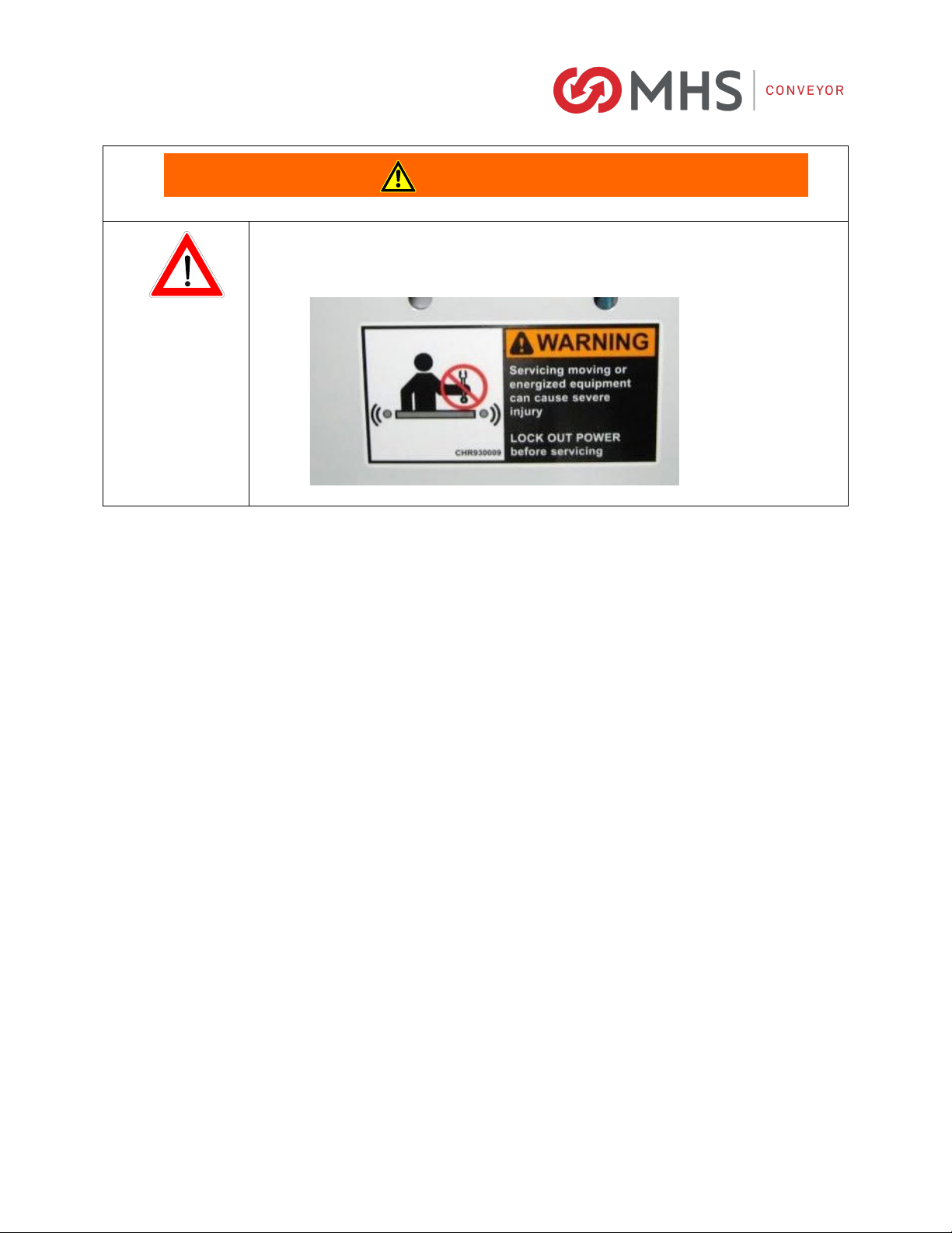
•After maintenance, REPLACE guards immediately.
•Keep ALL warning labels clean and clear of any obstructions.
•Never remove, deface, or paint over WARNING or CAUTION labels. Any damaged label
will be replaced by MHS Conveyor at no cost by contacting Lifetime Services.
•It is very important to instruct personnel in proper conveyor use including the location
and function of all controls.
•Special emphasis must be given to emergency stop procedures.
•It is important to establish work procedures and access areas, which do not require any
part of a person to be under the conveyor.
•It should be required that long hair is covered by caps or hairnets.
•Loose clothing, long hair, and jewelry must be kept away from moving equipment.
•Maintain enough clearance on each side of all conveyor units for safe adjustment and
maintenance of all components.
•Provide crossovers or gates at sufficient intervals where needed to eliminate the
temptation for personnel to climb over or under any conveyor.
•Walking or riding on a moving conveyor must be prohibited.
•Before performing maintenance on the conveyor, make sure the start-up controls are
locked out and cannot be turned on by any person other than the one performing the
maintenance.
•If more than, one crewmember is working on the conveyor, EACH CREW MEMBER MUST
HAVE A LOCK ON THE POWER LOCKOUT.
•All pneumatic devices must be de-energized and air removed to prevent accidental
cycling of the device while performing general maintenance.
•Make sure all personnel are clear of all conveyor equipment before restarting the
system.
•Before restarting a conveyor, which has been stopped because of an emergency, an
inspection of the conveyor must be made and the cause of the stoppage determined.
The starting device must be locked out before any attempt is made to correct the cause
of stoppage.
WARNING
XENOROL® IOM
P/N: 90480006 Rev Date: 10/01/2021 Page 12 of 161
•Before servicing or performing any work in the motor control panel, disconnect
and lock out air and the main incoming service. If only the panel disconnect is
off, the incoming side will still be hot.
WARNING

XENOROL® IOM
P/N: 90480006 Rev Date: 10/01/2021 Page 13 of 161
2.3 MHS CONVEYOR CONTROLS SAFETY GUIDELINES
The following basic conveyor control safety guidelines are recommended by MHS Conveyor even though
Business Partner may or may not purchase conveyor controls from MHS Conveyor. The items listed deal
with applications of controls equipment. The actual installation of the equipment must always follow the
National Electric Code and all other local codes.
Start-up Warning Horn
Ideally, all conveyors should be within sight of the conveyor start pushbutton. This allows the operator to
verify that no one is touching the conveyor or would be in danger if the conveyor were to start up.
If it is not possible to see the entire conveyor being started from the start pushbutton location, then some
form of audible warning device is required. It could be a horn, buzzer, bell, or anything unique to that
conveyor for that location. It should be loud enough to be heard at any point on the conveyor system. It
should sound for approximately five seconds after the start pushbutton is pushed, prior to the actual
running of conveyor. Any auxiliary equipment such as vertical lifts, turntables, etc., should also be
included in the warning circuitry.
Conveyors that stop and restart under automatic control could also require a horn warning prior to
restarting. If it is not easy to distinguish the difference between a fully stopped conveyor system and a
momentarily stopped conveyor section, then it is advisable to add a warning horn. All conveyor sections
that stop and restart automatically should be marked with appropriate signs or labels.
Start Pushbuttons
Start pushbuttons should be the flush type or guarded such that inadvertently leaning against them will
not actuate the conveyor. They should be provided with a legend plate clearly defining which conveyors
will be started.
Stop Pushbuttons
Stop pushbuttons should be the extended type such that any contact with it is sufficient to stop the
conveyor. They would also be provided with a legend plate clearly defining which conveyors will be
stopped.
Operator Controls
Additional operator controls should be designed into the system with the same guidelines that go into
start and stop pushbuttons, depending upon their function. Devices which are repeated on multiple
control stations, such as emergency stops, should be located at the same relative location on each
station (such as lower right corner).
Emergency Stops
All locations where an operator must work directly at the conveyor should be protected by an emergency
stop. An operator should not have to move from where he is to actuate the emergency stop.
Conveyors in areas of high pedestrian traffic should also be protected by emergency stop devices.
For all other instances, emergency stops should be located throughout a system such that it is possible to
shut down the system without having to walk too far. In these instances the emergency stop is used more
to protect the equipment from damage than to protect personnel.
Emergency stops can be of the pushbutton or cable operated switch type. The pushbutton type should be
a red, mushroom head maintained pushbutton which requires resetting after it is actuated. Cable
operated switches should trip by pulling the cable and require resetting at the switch.

XENOROL® IOM
P/N: 90480006 Rev Date: 10/01/2021 Page 14 of 161
Actuating an emergency stop must drop-out the start circuit, requiring restarting the system using the
start pushbuttons provided.
An emergency stop should normally stop all conveyors in the system. Very large systems may involve
dividing a system into zones of control based on proximity of personnel, safety hazards, walls obstacles,
etc.
Controls Logic
Solid state controls logic devices, such as programmable controllers are used extensively for conveyor
control. They are very reliable, but a hardware failure or software bug would cause an output to function
erratically. For this reason, start circuits, warning horn circuits, and emergency stops should usually be
configured using conventional relay logic.
Safety Switches
All conveyor control cabinets and motors should be provided with safety (or disconnect) switches. These
switches must have provisions for padlocking. As required for maintenance, equipment should be locked
in the off position.
Special Devices
Special devices and equipment such as vertical lifts, turntables, high speed conveyors, etc., all have
unique design and safety requirements. These should be looked at in each case to determine what the
requirements might be.
Rev 08/12/2021
XENOROL® IOM
P/N: 90480006 Rev Date: 10/01/2021 Page 15 of 161
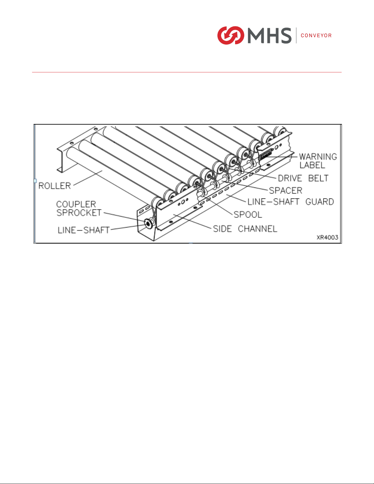
3INTRODUCTION TO XENOROL®
XenoROL rollers are driven by pre-tensioned polyurethane belts, which pull the drive spools against the
line-shaft. Each spool delivers a fixed amount of torque from the line-shaft to the rollers. This torque is
based on the drive belt tension and coefficient of friction between the spool and line-shaft. If the torque
requirement to drive the load on the rollers exceeds the fixed torque of the spool, the spool slips on the
line-shaft like a clutch.
XenoROL conveyor allows unequaled versatility with high speed, complete reversibility, and minimum
pressure accumulation. A major benefit of XenoROL line-shaft driven conveyor is the ability to power
straight sections and curves plus auxiliary devices from a single drive. Auxiliary equipment includes
transfers, spurs, adjoining parallel sections, merges, switches, sortation devices, powered guardrails,
etc.
PRECAUTIONS
TEMP. RANGE (AMBIENT): 35°F to 100°F. For temperature applications outside this range, consult the
Distributor Services Department.
ULTRAVIOLET RAYS: Avoid exposure of polyurethane belts to sunlight.
OILY OR WET CONDITIONS: Will impair frictional drive characteristics between spool and line-shaft.
CORROSIVE OR ABRASIVE SUBSTANCES: Will adversely affect various components, voiding the
warranty

XENOROL® IOM
P/N: 90480006 Rev Date: 10/01/2021 Page 16 of 161
3.1 DEFINITION OF TERMS
Accessory - A device that receives power from and contributes to the horsepower requirement of the
line-shaft.
Accumulation (Minimum Pressure) - Act of queuing, holding, or backing up of product on a conveyor.
Carrying Roller - The conveyor roller upon which the object being transported is supported. It has a
circumferential groove near one end to allow the drive belt to ride below the carrying surface.
Coefficient of Friction - A numerical expression of the ratio between the force of contact between two
surfaces and the resistant force tending to oppose the motion of one with respect to the other.
Conveyor Width - The dimension outside to outside of frame rails. For the inside dimension, the
abbreviation used is "BF" (between frames).
Coupler - A mechanical device, which connects segments of the line-shaft.
Coupler Chain - A double wide chain, plastic, or metal, which performs the function of connecting one
sprocket to an adjacent sprocket.
Coupler Sprocket - A sprocket located at the extreme end of a line-shaft, positioned to allow connection
to a second sprocket on another line-shaft by using a coupler chain.
Crossmember - Structural member, which is assembled between two side channels of a conveyor bed.
Drive - An assembly of mechanical, electrical, and structural components to provide power to line-shaft.
Drive Belt - An endless round belt manufactured from elastic material, typically urethane, connecting
spools to carrying rollers for transmitting rotation of line-shaft.
Drive Sprocket - The sprocket, which propels the chain or synchronous belt.
Frame - The structure, which supports the components of a conveyor bed consisting of formed channel
rails bolted together with square tubing crossmembers.
Guard Rail - Members paralleling the path of a conveyor and limiting the unit loads to movement in a
defined path.
Jump Chain - A drive chain or belt, which transmits power from one line-shaft to an adjacent parallel
line-shaft. A crossover between adjacent line-shafts within a common conveyor frame is called an
internal jump chain. A crossover between a line-shaft in one conveyor frame and a line-shaft in an
adjacent parallel conveyor frame is called an external jump chain.
Line-shaft - Shaft, which runs longitudinally within line-shaft conveyor to provide power transmission to
carrying rollers and accessory equipment.
Line-shaft Bearing - The pillow block style bearings in which the line-shaft rotates.
Line-shaft Curve - A curved conveyor section equipped with a line-shaft segmented with universals to
change the direction of product travel horizontally. The curve radius is measured to the inside face of
the inside frame rail.
Line-shaft Guard - Provided to prevent entanglement in rotating parts.

XENOROL® IOM
P/N: 90480006 Rev Date: 10/01/2021 Page 17 of 161
Roller Centers - Distance between center lines of adjacent rollers. For curves, roller centers are
measured at the inside radius.
Roller Groove - The groove that is fabricated into the carrying roller to provide a seat for the drive belt
below the carrying surface.
Speedup Spool - (See spool) a spool of larger diameter than adjacent spools assembled to the line-
shaft. The difference in diameters causes those carrying rollers powered by the speedup spools to rotate
faster than those driven by the smaller spools when driven by the same line-shaft.
Spool (Pulley) - A sheave or concave cylinder assembled on the line-shaft with slip fit to provide friction
drive to carrying rollers but also “slip” in case of stalled carrying rollers. Also contains and protects drive
belt.
Sprocket Ratio - The ratio of the number of teeth of the driven sprocket to the drive sprocket.
Tapered Roller - A conical conveyor roller for use in a curve with end and intermediate diameters
proportional to their radius.
Universal Joints - A device used to connect two intersecting line-shafts whose axes are not in a straight
line.
XenoBRAKE - Pneumatically operated pad mounted below the conveyor rollers used to stop the carrying
rollers upon signal by a sensor.
For more abbreviation or terms visit MHS Conveyor website at mhs-conveyor.com

XENOROL® IOM
P/N: 90480006 Rev Date: 10/01/2021 Page 18 of 161
4CAPACITY OF ROLLERS AND FRAMES
4.1 ROLLER
4.2 FRAME
Product Bottom
3/16"
Std.
5/32"
Option
1/8"
Option
12-3/4"
Std.
13-1/2"
Option
Soft, weak bottom, load unbalanced, uneven bottom, with
noticeable bumping. Ex.: plastic totes, wire or steel baskets,
lightweight corrugated (always use 3" centers).
15 10 630 25
Slight indentation, less than even loading. Ex.: normal corrugated
and plastic totes (includes most applications).
20 14 940 34
Firm, flat bottom and uniform loading. Ex.: heavy wall corrugated,
double wall corrugated and stiff treated materials
25 17 11 50 42
Hard & flat bottom, retaining some flexibility, uniform load
distribution. Ex.: plywood and fiberboard.
30 20 13 60 50
(Conveying Surface)
XR40
Note: Optional bearings with seals may reduce the roller drive capacity. If product conveys hard against the guard rail (ex.
where a transfer is used to square product against the guard rail), reduce the capacity by 25%.
DRIVE PER ROLLER BY TYPE OF BOTTOM
Drive Capacity per Roller (lbs.)
XR48
1-4" Dia. Belts
10’ 9’ 8’ 7’ 6’ 5’
XR40 4-1/2" Deep
60#/ft. 90#/ft. 145#/ft. 235#/ft. 395#/ft. 710#/ft.
XR40/XR48 9" Deep
215#/ft. 305#/ft. 450#/ft. 670#/ft. 1115#/ft. 1960#/ft.
FRAME CAPACITY
Support Centers (lbs./ft.)
Frame Channel Depth
Note: The 4-1/2" deep frame has more capacity when supported on 8’ centers than XR40 roller drive capacity. The 9" deep frame has
more capacity when supported on 9’ centers than XR40 or XR48 roller drive capacity.

XENOROL® IOM
P/N: 90480006 Rev Date: 10/01/2021 Page 19 of 161
4.3 MINIMUM PRESSURE ACCUMULATION
When conveyed product is stopped, the friction between the product and the roller stops the roller, drive
belt, and spool. Though the shaft continues to turn, only minimal friction exists between the inner
surface of the spool and the line-shaft surface. The pressure of accumulated product is independent of
its weight and is determined by the belt tension.
Average lbs. Pressure per roller
Long lengths of accumulated product must be zoned with stop devices. This reduces the total line
pressure into several smaller increments. Stopping devices are also used to accumulate product prior to
the curves. Air or electrical sensor controls can be supplied to activate the stop device. Always consult
the Distributor Services Department.
Reduction of Line Pressure
Pressure of accumulated articles can be reduced by removing belts at specified intervals on the
conveyor. For example, accumulated pressure can be reduced 25% by removing every fourth belt.
CAUTION: THE DRIVE CAPACITY IS ALSO REDUCED 25%.
OPTIONAL BELTS: Consider the optional drive belts for lighter loads. This will increase conveyor length
on a single drive while reducing horsepower requirements.
3/16" Std. 5/32" Option 1/8" Option
1/4" x 12-3/4"
Std.
1/4" x 13-1/2"
Option
1# 0.7# 0.5# 2# 1.7#
XR40
XR48
Pressure Per Roller

XENOROL® IOM
P/N: 90480006 Rev Date: 10/01/2021 Page 20 of 161
5RECEIVING &SITE PREPARATION
5.1 GENERAL
MHS Conveyor XenoROL® sorters are shipped in subassemblies. These subassemblies are packaged to
guard against damage in shipment, when handled properly.
Examination immediately following unloading will show if any damage was caused during shipment. If
damage is evident, claims for recovery of expenses to repair damage or replace components must be
made against the carrier immediately. While unloading, a check must be made against the Bill of
Lading, or other packing lists provided, to confirm full receipt of listed items.
•
TAKE CARE DURING THE REMOVAL OF EQUIPMENT FROM THE CARRIER.
Remove small
items and boxes first. Pull and lift only on the skid, not on the frame, cross member or any
part of the equipment.
Preparation of Site
After the conveyor is received, move it to the installation site or designated dry storage area as soon as
possible. Clean up all packing material immediately before parts get lost in it. Loose parts should
remain in the shipping boxes until needed.
Prior to starting assembly of the conveyor, carefully check the installation path to be sure there are no
obstructions that will cause interference. Check for access along the path needed to bring in bed
sections and components closest to the point where they are needed. It is often necessary to give the
area along the system path a general cleanup to improve installation efficiency, access, and accuracy.
CAUTION
Other manuals for XenoROL XR40
1
This manual suits for next models
2
Table of contents
Other MHS Boilers Industrial Equipment manuals


Popular Industrial Equipment manuals by other brands


York
York AHS8 UH Series User's information, maintenance and service manual

Westell
Westell Boxer BXM3019-10HE manual

PCB Piezotronics
PCB Piezotronics YT352C34 Installation and operating manual

PGR
PGR PA-PF Series Maintenance and operation instructions

Sumitomo
Sumitomo Bevel BUDDYBOX 4 Series Maintenance manual

Siemens
Siemens 3TS1722-0A 5-8K Series operating instructions


