manuals.online logo
Brands
  1. Home
  2. •
  3. Brands
  4. •
  5. WAMGROUP
  6. •
  7. Industrial Equipment
  8. •
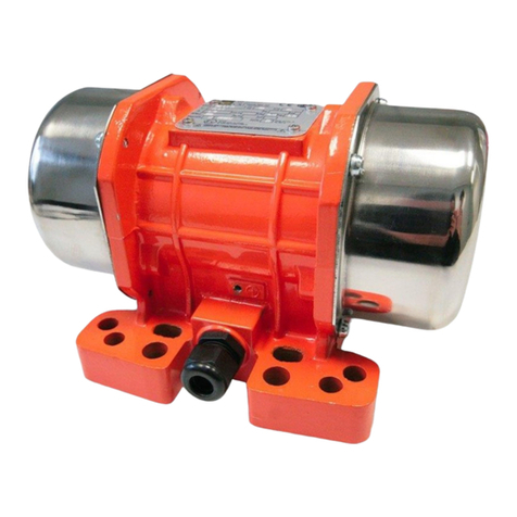
  9. WAMGROUP OLI MVE 60/3 User manual

WAMGROUP OLI MVE 60/3 User manual

Allrightsreserved©WAMGROUP
•ELECTRIC EXTERNAL MOTOVIBRATORS
•
ELEKTRISCHEAUSSENRÜTTLER
•WIBRATOR ELEKTRYCZNY PRZYCZEPNY
•
MOTOVIBRATORIELETTRICIESTERNI
MVE
CATALOGUE No. 1010
ISSUE
A2 DATEOFLATESTUPDATE
08.01
CREATIONDATE
CIRCULATION
100
03.00
1010. INDEX
MVE -
MVE -
MVE -
MVE -
INDEX
INHALTSVERZEICHNIS
SPIS TRESCI
INDICE
TECHNICAL CATALOGUE
INTRODUCTION...............................................................................................
DESCRIPTION.................................................................................................
DIMENSION.....................................................................................................
TECHNICAL CHARACTERISTICS.....................................................................
KATALOGE TECHNICZNY
WPROWADZENIE..............................................................................................
OPIS::::::::::::::.................................................................................................
WYMIARY:::::::::::...........................................................................................
DANE TECHNICZNE::::::::::::::::::::::::::...............................................................
MAINTENANCE CATALOGUE
OPERATION AND MAINTENANCE......................................................................
DOKUMENTACJA TECHNICZNO RUCHOWA
INSTRUKCJA OBSLUGI I UZYTKOWANIA...........................................................
SPARE PARTS CATALOGUE
SPARE PARTS................................................................................................
KATALOG CZESCI ZAMIENNYCH
CZESCI ZAMIENNE:..................................................................................
TECHNISCHER KATALOG
EINFÜHRUNG.............................................................................................
BESCHREIBUNG........................................................................................
SCHNECKEN..............................................................................................
TECHNISCHE MERKMALE........................................................................
CATALOGO TECNICO
INTRODUZIONE.........................................................................................
DESCRIZIONE............................................................................................
INGOMBRO................................................................................................
CARATTERISTICHE TECNICHE................................................................
WARTUNGS-KATALOG
BETRIEBS- UND WARTUNGSANLEITUNG................................................
CATALOGO DI MANUTENZIONE
USO E MANUTENZIONE............................................................................
ERSATZTEILKATALOG
ERSATZTEILE...........................................................................................
CATALOGO RICAMBI
PEZZI DI RICAMBIO...................................................................................
2
3
1
3
T.01
T.02
T.03
T.04 > 05
T.01
T.02
T.03
T.04 > 05
M.01 > 16
M.01 > 16
R.01 > 10
R.01 > 10
TECHNICAL CATALOGUE
•ELECTRIC EXTERNAL MOTOVIBRATORS
TECHNICALCATALOGUE
•
ELEKTRISCHE AUSSENRÜTTLER
TECHNISCERKATALOG
•WIBRATORY ELEKTRYCZNE PRZYCZEPNE
KATALOGTECHNICZNY
•
MOTOVIBRATORIELETTRICIESTERNI
CATALOGO TECNICO
MVE
Allrightsreserved©WAMGROUP
1
CATALOGUE No. 1010.T
ISSUE
A2 DATEOFLATESTUPDATE
08.01
CREATIONDATE
CIRCULATION
100
03.00
1
1010.T.
MVE -
MVE -
MVE -
MVE -
INTRODUCTION
EINFÜHRUNG
WPROWADZENIE
INTRODUZIONE 01
The range of MVE-type exter-
nal motovibrators is the result
of forty years of experience in
vibrating technology for the con-
struction industry as well as for
other industrial applications
world-wide.The rotary vibrators
afford a guarantee of long term
durability, reflecting the care tak-
en over selection of components
and the high level of precision
adopted in manufacture, whilst
maintenanceis minimal andsim-
ple in the extreme.
GENERALINSTRUCTIONS
Readthese instructions carefully
before using the equipment, and
keep the manual in a safe place
forfuture reference.
Thewarrantyisvalidformanufac-
turing defects for a period of
twelve months from the date of
purchase (attested by the docu-
ment accompanying the goods).
The warranty covers all the me-
chanicalpartsand excludes elec-
trical parts and those subject to
wear. The warranty will be invali-
dated thus freeing the manufac-
turer of any direct or indirect re-
sponsibility in the following cas-
es: if the product is mishandled
or used improperly, if repairs or
modificationsare made by unau-
thorisedpersonnel, or if non-orig-
inal spare parts are used.
Thematerialsent for repair under
the warranty are returned CAR-
RIAGEPAID.
Die Baureihe der MVE-Außen-
rüttler basiert auf einer vierzig-
jährigen Erfahrung auf dem Ge-
biet der Vibrationstechnik in der
Bauindustrie und in diversen an-
deren industriellen Einsätzen
weltweit. Besondere Sorgfalt bei
der Auswahl der Komponenten
und eine präzise Fertigung ge-
währleisteneinenhohen Grad an
Wartungsfreundlichkeit sowie
eine lange Lebensdauer der Ge-
räte.
ALLGEMEINES
Vor der erstmaligen Anwendung
dieseAnweisungen aufmerksam
durchlesenunddasHandbuch für
zukünftige Benutzungen aufbe-
wahren.
DieGarantie giltab dem Kaufda-
tum (siehe Warenbegleitschein)
auf die Dauer von zwölf Mona-
ten und garantiert den Rüttler
gegenFabrikationsfehler.
DieGarantie deckt alle mechani-
schen Teile ab, schließt jedoch
alleVerschleißteileund das elek-
trische Teile aus. Die Garantie
verfällt, und damit auch jede di-
rekte und indirekte Haftung des
Herstellers,wenn der Rüttler ma-
nipuliert oder auf bestimmungs-
widrige Weise benutzt wurde,
wennReparaturen oder Abände-
rungen durch dazu nicht autori-
siertes Personal vorgenommen
wurden, wenn keine Original-Er-
satzteileverwendet wurden.
Mit Antrag auf Garantie an den
Hersteller eingeschicktes Mate-
rialmußFRACHTFREI zugestellt
werden.
Typoszereg wibratorow MVE
bazuje na wieloletnim doswiad-
czeniu w zakresie techniki wibra-
cjiwbranzybudowlanej i innych
branzach przemyslowych na ca-
lymswiecie.
Wybor wlasciwych podzespolow
i precyzyjna produkcja gwaran-
tuja wysoki stopien niezawod-
nosci oraz trwalosc urzadzen.
WSKAZOWKIOGOLNE
Przed uruchomieniem nalezy
uwaznie zapoznac sie z instru-
kcjaorazprzechowywac ja w po-
blizu urz adzenia.
Gwarancjaobowiazuje oddaty
sprzedazy i wynosi
12 miesiecy oddatyzakupu
Gwarancja obejmuje bledy
produkcyjne.
Gw arancjaobejmuje wszystkie
czescimechaniczne,nie obejmuje
czesci zuzywajacych sie oraz
elektrycznych.
Gwarancjapodlegautraciewprzy-
padku (a tym samym producent
nie bierze odpowiedzialnosci
posredniejlub bezposredniej)
zastosowania wibratora nie-
zgodnego z prze znaczeniem
naprawprzeprowadzonych
przez niekompetentny personel
lub
czesci nieor.
wprzypadku zastosowania
czesci nieoryginalnych.
La gamma dei vibratori MVE è il
risultato di 40 anni di esperienza
applicazioni nei settori edili ed
industriali, sia a livello nazionale
che internazionale. La cura nella
scelta della componentistica e
l’alta precisione delle lavorazioni
sono garanzia della durata nel
tempodelmotovibratoreconope-
razionidimanutenzioneestrema-
mente semplici e ridotte.
NORMEGENERALI
Leggete attentamente queste
istruzioni prima di utilizzare il vi-
bratore e custodite questo ma-
nuale per futuri riferimenti.
Lagaranzia è validacontro difetti
difabbricazione per un periododi
dodici mesi dalla data d’acqui-
sto (fa fede il documento accom-
pagnatorio della merce). La ga-
ranzia copre tutte le parti mec-
caniche ed esclude quelle sog-
gettead usura e quelleelettriche.
La garanzia decade, e con essa
ogni responsabilità diretta o indi-
retta, qualora il prodotto sia sta-
to manomesso o utilizzato in
modoimproprio, siano statefatte
riparazionio modifiche da perso-
nale non autorizzato, siano stati
utilizzati ricambi non originali.
I materiali resi per riparazione in
garanzia vanno resi in PORTO
FRANCO.
03.00
1
1010.T.
MVE -
MVE -
MVE -
MVE -
1Vibrator bodyRüttlergehäus Korpus Corpo vibratore
2TerminalboxKlemmenkastenpuszka zaciskowa Morsettiera
3CableglandKabeldurchführungOslonka przewodu Pressacavo
4Bearing-holder flangeLagertrageflanschObudowa lozysk Flangia portacuscinetto
5StatorStänderStatorStatore
6Rotor shaftRotorwelleWalekwirnika Albero rotore
7WeightsUnwuchtmassenPrzeciwwaga Masse
8BearingWälzlagerLozysko Cuscinetto
I motovibratori MVE sono pro-
gettati e costruiti secondo le nor-
mative vigenti:
- Classe isolamento F
- Tropicalizzazione di serie
- Protezione IP 65
- Temperaturadifunzionamento:
da -30°C a + 40°C
- Normative applicate :
IEC34.1
CEI 2/3; 73/23/CEE
89/392/CEE
EN 292
EMC 89/336/CE
CSA
DESCRIPTION
BESCHREIBUNG
OPIS
DESCRIZIONE
Wibratory MVE produkowane
sa zgodnie z obowiazujacymi
normami :
-Klasaizolacji F
-seryjna izolacja uzwojenia
- zabezpieczenie IP 65
-Zakres pracy w temperaturze
-30° do +40°C
-Normyobowiazujace :
IEC34.1
CEI2/3 ; 73/23/CEE
89/392/CEE
EN 292
EMC 89/336/CE
CSA
Die MVE-Außenrüttler wurden
in Konformität mit den geltenden
Normen entwickelt und konstru-
iert:
- Isolationsklasse F
- Serienmäßigtropengeschützt
- Schutzart IP 5645
- Betriebstemperatur: -30°C bis
+40°C
- AngewendeteNormen:
IEC34.1
CEI 2/3;73/23/EWG
89/392/EWG
EN 292
EMC 89/336/EWG
CSA
MVE motovibrators are de-
signed and constructed accord-
ing to existing regulations:
- Insulation Class F
- Standard tropicalization
- Protection degree IP65
- Operating temperature: from
–30°C to +40°C
- Standards applied:
IEC34.1
CEI2/3;73/23/EEC
69/392/EEC
EN 292
EMC 89/336/EC
CSA
02
03.00
1
1010.T.
MVE -
MVE -
MVE -
MVE -
DIMENSION
ABMESSUNGEN
WYMIARY
INGOMBRO 03
SizeABCDEFØG
holes
Bohr.
Sruby
fori
HILMNPG
10 62 106 210 130 135 25 8.5 4 46 102 110 45 82 11
10A 62 106 220 130 135 25 8.5 4 46 102 110 50 82 11
20 62-74 106 225 130 145 33 8.5 4 62 120 115 45 120 11
30 90 125 255 155 170 20 10.5 4 75 135 145 45 140 11
40 105 140 338 175 195 40 13 4 90 176 160 75 160 13.5
50 120 170 390 204 203 40 15 4 92 145 180 90 170 13.5
60 140 190 490 230 233 45 17 4 115 180 220 110 220 16
70 155 225 630 280 305 28 21 4 135 265 220 165 265 3/4"
80 180 280 720 340 350 35 24.5 4 155 300 250 165 300 3/4"
90 200 320 915 430 420 50 27.5 6 185 365 310 210 365 3/4"
08.01 /
03.00
1
1010.T.
MVE -
MVE -
MVE -
MVE -
TECHNICAL CHARACTERISTICS
TECHNISCHE MERKMALE
DANE TECHNICZNE
CARATTERISTICHE TECNICHE
MVE 3000 / 3600 RPM 3 PHASE
MVE 60/3 80 95 0.27 0.16 0.32 0.18 71 87 A 8+8 A 5+5 7.11 6.48 4.8 4.5 10
MVE 100/3 100 110 0.33 0.19 0.32 0.18 99 107 A 12+12 A 9+9 9.88 7.41 5.3 5.1 10A
MVE 200/3 180 210 0.60 0.35 0.62 0.35 198 190 A 12+12 A 8+8 19.70 13.13 7.1 6.7 20
MVE 300/3 270 285 0.90 0.52 0.83 0.45 311 317 B B 34.23 26.62 11.0 10.7 30
MVE 400/3 300 360 1.00 0.58 1.05 0.60 400 380 B B 40.45 26.62 12.3 12.0 30
MVE 500/3 500 580 1.67 0.96 1.69 0.97 516 515 B B 51.28 35.50 21.0 20.0 40
MVE 700/3 660 750 2.18 1.25 2.16 1.24 750 734 B B 74.95 50.68 23.8 23.4 40
MVE 800/3 750 900 2.50 1.45 2.62 1.50 788 782 B B 78.40 53.90 30.2 29.4 50
MVE 1200/3 950 1150 3.20 1.85 3.35 1.95 1018 1049 B B 101.26 72.33 32.1 31.3 50
MVE 1300/3 1300 1380 4.24 2.44 3.92 2.25 1386 1333 B B 137.87 91.92 36.8 36.6 50
MVE 1600/3 1570 1600 5.12 2.94 4.54 2.61 1571 1599 B B 156.26 110.30 49.6 48.1 60
MVE 1800/3 2000 2100 6.52 3.75 5.96 3.42 1848 1866 B B 183.83 128.58 54.1 51.7 60
MVE 2200/3 2200 2250 7.10 4.07 6.31 3.62 2033 1999 B B 202.22 137.87 60.9 58.6 60
MVE 2300/3 2400 2450 7.72 4.44 6.87 3.94 2310 2266 B B 229.79 156.26 64.1 62.8 60
MVE 3200/3 2900 2900 9.21 5.30 8.03 4.61 3423 3103 C C 348.52 218.84 96.0 91.0 70
MVE 4000/3 2900 2900 9.21 5.30 8.03 4.61 3990 3743 C C 390.30 261.20 98.0 93.0 70
MVE 5000/3 4000 4000 12.60 7.22 11.00 6.28 5188 5006 C C 516.42 358.18 111.0 106.0 70
MVE 9000/3 10000 9300 31.00 17.80 25.10 14.40 9102 9010 C C 902.20 612.08 215.0 211.0 90
MVE 1500 / 1800 RPM 3 PHASE
MVE 1000 / 1200 RPM 3 PHASE
Type
Electrical data - Elektrische Daten
Dane elektryczne - DatielettriciMechanical data - Mechanische Daten
Dane méchaniczne-DatimeccaniciWeight
Gewicht
Ciezar
Peso
kg
Size
Größe
Taille
Grandezza
WA max.
50 Hz A max.
60 Hz Fc max.
kg
Weights
Unwuchtmassen
Przeciwwagi
Moment-Arbeitsmoment
Moment-Momento
kg / mm
50 Hz 60 Hz 230 V 400 V 264 V 460 V 50 Hz 60 Hz Type 50 Hz 60 Hz 50 Hz 60 Hz
50 Hz 60 Hz
04
MVE 40/15 40 48 0.19 0.11 0.19 0.11 32 44 A 13+13 A 12+12 10.70 9.88 5.5 5.4 10A
MVE 90/15 90 108 0.46 0.26 0.43 0.25 90 97 B B 28.31 21.34 7.3 7.1 20
MVE 200/15 160 170 0.85 0.49 0.87 0.50 183 198 C C 72.84 54.63 13.4 12.7 30
MVE 400/15 300 350 1.46 0.84 1.50 0.86 388 399 C C 154.54 110.39 26.2 25.6 40
MVE 500/15 350 400 1,84 1.06 1.90 1.09 518 515 C C 206.40 143.00 28.0 27.1 40
MVE 700/15 620 725 2.29 1.32 2.45 1.41 693 699 C C 275.75 193.02 31.4 30.9 50
MVE 1400/15 900 1080 2.97 1.71 3.10 1.78 1406 1434 C C 559,30 396,17 51.0 47.5 60
MVE 1700/15 1150 1280 3.75 2.16 3.64 2.09 1757 1687 C C 699,12 466,08 58.0 54.5 60
MVE 2400/15 1600 1900 5.22 3.00 5.54 3.20 2402 2447 C C 959,34 688,12 67.8 66.0 60
MVE 3800/15 2220 2600 7.14 4.12 7.23 4.15 3811 3803 C C 1520.80 1062.80 116.0 110.3 70
MVE 5500/15 3560 3450 11.30 6.50 9.55 5.48 5560 5310 C C 1984.30 1363.12 158.5 152.1 80
MVE 7200/15 5000 6000 16.70 9.60 16.40 9.41 7188 6830 C C 2604.10 1824.77 210.0 196.7 80
MVE 9000/15 7500 8480 23.20 13.40 22.90 13.10 8984 9012 C C 3351.10 2494.12 312.0 301.0 90
MVE 200/1 180 210 0.83 0.48 0.88 0.51 185 194 C C 166 121 24.8 26.1 40
MVE 300/1 350 380 1.17 0.67 1.11 0.64 308 294 C C 276 183 33.9 33.1 50
MVE 800/1 680 760 2.24 1.29 2.19 1.26 781 746 C C 699 466 51.0 48.5 60
MVE 1100/1 750 800 2.47 1.42 2.30 1.32 1067 1119 C C 955 699 64.5 55.0 60
MVE 1600/1 1100 1300 4.92 2.83 5.61 3.22 1622 1550 C C 1427 946 73.6 67.8 60
MVE 2600/1 1960 2100 6.31 3.63 5.89 3.38 2580 2595 C C 2311 1621 130.0 116.0 70
MVE 3800/1 2500 3000 8.13 4.67 8.50 4.88 3830 3842 C C 3434 2406 185.0 166.0 80
MVE 5200/1 3790 4000 12.00 6.92 11.10 6.36 5220 5300 C C 4678 3311 239.0 216.0 90
MVE6500/1 4300 4980 13.50 7.76 13.60 7.81 6510 6538 C C 5836 4042 261.0 233.0 90
MVE 8000/1 7050 7500 21.80 12.60 20.30 11.60 8043 7995 C C 7225 5007 321.0 289.0 90
MVE 9000/1 7510 8260 23.00 13.20 22.00 12.60 8672 8697 C C 7751 5394 325.0 285.0 90
08.01 /
TECHNICAL CHARACTERISTICS
TECHNISCHE MERKMALE
DANE TECHNICZNE
CARATTERISTICHE TECNICHE
MVE 250/075 350 380 1.17 0.67 1.11 0.64 235 245 C C 374.18 266.93 22.5 24.0 50
MVE 650/075 500 600 1.67 0.96 1.75 1.00 659 640 C C 1048.25 698.14 53.0 50.5 60
MVE 900/075 650 780 2.15 1.23 2.24 1.29 908 843 C C 1444.85 932.16 66.0 61.0 60
MVE 1300/075 980 1110 3.24 1.86 3.19 1.83 1112 1480 C C 1582.12 1582.12 79.0 79.0 60
MVE 2100/075 1500 1170 4.89 2.81 5.03 2.89 1470 2100 C C 2302.22 2302.75 130.0 130.0 70
MVE 3100/075 2020 2310 6.59 3.79 6.56 3.77 2231 3106 C C 3431.43 3431.88 183.0 183.0 80
MVE 4200/075 2840 3340 9.14 5.26 9.36 5.37 2984 4230 C C 4658.87 4658.20 238.0 238.0 90
MVE 5300/075 3980 4330 12.60 7.28 12.00 7.90 3680 5300 C C 5844.05 5844.77 263.0 263.0 90
MVE 6500/075 4950 5850 15.50 8.93 16.00 9.20 4512 6430 C C 7210.23 7210.09 320.0 320.0 90
MVE 750 / 900 RPM 3 PHASE
MVE 3000 / 3600 RPM SINGLE PHASE
DIRECT CURRENT VIBRATORS
A
N°
of blades-Lamellen
lamelles - lamelle 5 + 5 8 + 8 9 + 9 12 + 12
F.c%
for blade - pro Lamelle
par lamelle - per lamella 40 25 22.2 16.7
“A” “B” “C”
1
1010.T.
MVE -
MVE -
MVE -
MVE -
Type
Electricaldata- ElektrischeDaten
Daneelektryczne -DatielettriciMechanical data - Mechanische Daten
Dane mechaniczne - DatimeccaniciWeight
Gewicht
Ciezar
Peso
kg
Size
Größe
Wielkosc
Grandezza
WA max.
50 Hz A max.
60 Hz Fc max.
kg
Weights
Unwuchtmassen
Przeciwwagi
Moment-Arbeitsmoment
Moment-Momento
kg / mm
50 Hz 60 Hz 230 V 400 V 264 V 460 V 50 Hz 60 Hz Type 50 Hz 60 Hz 50 Hz 60 Hz
50 Hz 60 Hz
05
03.00
Type
Electrical data
Elektrische Daten
Données électriques
Dati elettrici
Mechanical data - Mechanische Daten
Données mécaniques - Dati meccanici Weight
Gewicht
Poids
Peso
kg
Size
Größe
Taille
Grandezza
V W A max. Fc max.
kg
Weights
Unwuchtmassen
Masses - Masse
Moment-Arbeitsmoment
Moment-Momento
kg / mm
MVE 90 CC-24 24 160 6.67 200 A 12 + 12 20.86 6.5 20
MVE 90 CC-12 12 160 13.30 200 A 12 + 12 20.86 6.5 20
MVE 90 CC-230 230 200 1.2 240 A 5 + 5 19.51 6.2 20
Type
Electrical data
Elektrische Daten
Dane elektryczne
Dati elettrici
Mechanical data - Mechanische Daten
Dane machaniczne -DatimeccaniciWeight
Gewicht
Ciezar
Peso
kg
Size
Größe
Wielkosc
Grand.
WA max.
50 Hz A max.
60 Hz Fc max.
kg
Weights
Unwuchtmassen
Przeciwwagi
Moment
Arbeitsmoment
Moment-Momento
kg / mm
50
Hz 60
Hz 230 V 115 V 50
Hz 60
Hz
Type 50 Hz 60 Hz 50
Hz 60
Hz
50 Hz 60 Hz
MVE 60/3 M 80 95 0.43 1.03 66 60 A 8+8 A 5+5 7.11 6.48 4.8 4.5 10
MVE 100/3 M 100 120 0.54 1.30 99 107 A 12+12 A 9+9 9.88 7.41 5.3 5.1 10A
MVE 200/3 M 130 150 0.71 1.63 197 213 A 12+12 A 8+8 19.70 13.13 7.1 6.7 20
MVE 300/3 M 290 320 1.58 3.48 344 290 B B 30.96 21.85 11 10.7 30
MVE 500/3 M 520 550 2.83 5.98 530 552 B B 51.28 35.50 21 20.7 40
MVE 800/3 M 850 880 4.62 9.57 793 879 B B 78.40 53.90 30.2 29.4 50
08.01 /
MAINTENANCE
•ELECTRIC EXTERNAL MOTOVIBRATORS
INSTALLATION,OPERATIONANDMAINTENANCE
•
ELEKTRISCHEAUSSENRÜTTLER
EINBAU-,BETRIEBS-UNDWARTUNGSANLEITUNG
•WIBRATORY ELEKTRYCZNE PRZYCZEPNE
MONTAZ,INSTRUKCJA UZYTKOWANIAIEKSPLOATACJI
•
MOTOVIBRATORIELETTRICIESTERNI
INSTALLAZIONE, USOEMANUTENZIONE
MVE
Allrightsreserved©WAMGROUP
2
CATALOGUE No. 1010.M
ISSUE
A2 DATEOFLATESTUPDATE
08.01
CREATIONDATE
CIRCULATION
100
03.00
2
1010.M.
MVE -
MVE -
MVE -
MVE -
OPERATION AND MAINTENANCE
BETRIEBS- UND WARTUNGSANLEITUNG
INSTRUKCJA UZYTKOWANIA
USO E MANUTENZIONE
A) ADDRESS OF DEALER OR
LOCAL SERVICE POINT A) INDIRIZZO RIVENDITORE O
PUNTO DI ASSISTENZA
LOCALE
A) ANSCHRIFT DES HÄND-
LERS ODER LOKALEN KUN-
DENDIENSTES
A) ADRESSPRZEDAWCY
LUB PUNKTU NAPRAWY
B) INTERPRETATION OF THE
IDENTIFICATION PLATE
For a correct identification of the
vibrator, refer to serial no. which
is included in the acknowledge-
ment of order, in the invoice and
on the plate on the vibrator.
C) CONTRAINDICATIONS TO
USE
lfthe customer observesthenor-
mal caution (typical of this kind
of equipment) together with the
indicationscontainedinthisman-
ual, work is safe.
The vibrator must not be started
before the vibrator itself, as well
as the plant it is going to be in-
stalled in, have been declared in
conformitywith the EuropeanDi-
rective14/06/1982(89/392/EEC)
It is the plant designer’s / plant
fitter’s responsability to design
and install all necessary protec-
tion in order to avoid that break-
ing and / or yielding of the equip-
ment or of parts of it might dam-
age people and / or parts of the
plant.
B) INTERPRETATION DES TY-
PENSCHILDES
Zureindeutigenldentifikation des
Rüttlers muß auf die in der
Auftragsbestätigung,inderRech-
nungsowieauf dem Gerät ange-
brachtenTypenschild befindliche
Produktionsnummer Bezug ge-
nommenwerden.
C) KONTRAINDIKATIONEN
ZURBENUTZUNG
Esbestehen keineKontraindika-
tionen zur Benutzung, sofern die
allgemein üblichen Vorsichts-
maßnahmenfürGerätedieserArt
sowie die in dieser Dokumen-
tation enthaltenen, speziellen
Vorschriften befolgtwerden.
Das Gerät darf nicht in Betrieb
genommenwerden, bevor sowohl
es selbst, als auch die Anlage,
in die es eingebaut wird, mit den
Vorschriften der Direktive 14/06/
1982 (89/392/EEC) für konform
erklärtwurde.
Esliegt in derVerantwortungdes
Anlagenplanersbzw.-aufstellers,
alle notwendigen Schutzvorrich-
tungenvorzusehen,welcheesver-
hindern,daßdurch einen Geräte-
oder Teiledefekt Personen- und/
oder Sachschäden verursacht
werden.
B) IDENTYFIKACJA TABLI-
CZKI ZNAMIONOWEJ
W celu wlasciwej identyfikacji
wibratoranalezy sprawdzic
numer fabryczny podany
na tabliczce znamionowej,
na fakturze.
C) PRZECIWWSKAZANIA
ZASTOSOWAN
Nieistnieja przeciwwskazania
zastosowano ile bedazastosowane
srodki bezpieczenstwa ktore
nalezy zachowac podczas ob-
chodzenia sie z tego typu urza-
dzeniami elektrycznymi.
Urzadzenie nie moze byc uru-
chomione (dotyczy rowniez
wibratora ), jezeli nie jest zgodne
z dyrektywa 14/06/1982
(89/392/ECC).
Projektant i wykonawca instala-
cji odpowiada za zastosowanie
urzadzen zabezpieczajacych
osoby lubrzeczyprzed spowodo-
waniem usykodzen lub obrazen
B) INTERPRETAZIONE DELLA
TARGHETTA
Per una corretta identificazione
delvibratore, bisogna fare riferi-
mento alnumerodimatricolache
si trova sulla conferma d’ordine,
sulla fattura e sulla targhetta po-
sta sul vibratore stesso.
C) CONTROINDICAZIONI AL-
L’USO
Non vi è nessuna controin-
dicazioneall’uso,se vengono os-
servate le normali precauzioni
per prodotti di questo tipo unita-
mente alle indicazioni riportate
su questo manuale.
E’ Inoltre vietato metterle in fun-
zione prima che la macchina/im-
piantonel qualedevonoesserein-
stallate sia dichiarato conforme
alle disposizioni della direttiva
14/06/1982(89/392/EEC).
In quest’ambito è cura dell’im-
piantista / installatore predispor-
re ed installare tutti gli accorgi-
menti / protezioni al fine di evita-
redannia cose o persone incaso
di rotture e conseguente caduta
di pezzi.
01
2
1010.M.
MVE -
MVE -
MVE -
MVE -
03.00
OPERATION AND MAINTENANCE
BETRIEBS- UND WARTUNGSANLEITUNG
INSTRUKCJA UZYTKOWANIA
USO E MANUTENZIONE 02
D) TRANSPORT - HANDLING
D1) UNLOADING AND
HANDLING
On arrival prior to unloading
checkifnatureand quantity of the
goods comply with the acknowl-
edgementof order.
Ifany parts are damagedthrough
transport immediately state your
claims in writing on the consign-
ment note (waybill). The driver is
obliged to accept this and to
leave you a copy. Send off your
claims without hesitation to the
manufacturer if you received the
goods free destination or di-
rectly to your shipping agent.
If you fail to state your claims
on arrival of the goods accep-
tance may be denied.
D)TRANSPORT-HANDLING
D1)ABLADEN UND
HANDLING
BeimEmpfangderLieferungkon-
trollieren, ob Ware in Beschaffen-
heit und Menge mit den Angaben
in der Auftragsbestätigung über-
einstimmt.
Eventuelle Unstimmigkeiten und/
oderSchäden müssen unverzüg-
lichinderhierfürvorgesehenenRu-
brikdes Frachtbriefeseingetragen
werden. Der Fahrer ist dazu ver-
pflichtet, die Reklamation entge-
gen zu nehmen und dem Emp-
fängereine Kopie des Frachtbrie-
fes zu überlassen. Sollte es sich
umeine Frei-Haus Lieferung han-
deln, muß der Empfänger die Re-
klamation an den Lieferanten
schicken. Ist der Kunde selbst
Frachtzahler, direkt an den Spe-
diteur. Ein Entschädigungsan-
spruch besteht nur dann, wenn
dieReklamation beimWarenemp-
fang in der o.g. Weise erfolgt ist.
D) TRASPORTO-RICEVIMENTO
D1) SCARICO E
MOVIMENTAZIONE
Al ricevimento della merce con-
trollarese la tipologiae la quanti-
tà corrispondono con i dati della
confermad’ordine.
Eventualidannidevonoesserefat-
ti presenti immediatamente per
iscritto nell’apposito spazio della
lettera di vettura. L’autista è ob-
bligato ad accettare tale reclamo
e lasciarne una copia a Voi. Se
lafornituraèfrancodestino,invia-
te il Vs. reclamo a noi, altrimenti
direttamente allo spedizioniere.
Senonrichiedereteidanni imme-
diatamenteall’arrivodella merce,
la vostra richiesta potrebbe non
essere accolta.
D) TRANSPORT- ODBIOR
D1) ROZLADUNEK I OBSLUGA
Podczas odbioru towaru nalezy
sprawdzic zgodnosc ilosci oraz
typu wibratora z zamawianym.
Ewentualne niezgodnosci lub
u szkodzenianalezyzglosic
przewoznikowi w odpowiedniej
rubrycelistu przewozowego.
Kierowca zobowiazany jest do
przyjecia reklamacji i przekazania
kopii listu odbiorcy.
Jezeli towar dostarczono na
bazie loco odbiorca, odbiorca
pow inien wyslac reklamacje do
dostawcy.
Reklamacja moze byc rozpa-
trzona pod w/w warunkami.
03.00
2
1010.M.
MVE -
MVE -
MVE -
MVE -
E) INSTALLATION
Themotovibratorsaresupplied in
single or multiple packaging, or
palletized according to the type
anddimensions. Storethemotovi-
brators in a place where the hu-
midity is less than 60%, and the
minimum temperature is not less
than 5°C.
Before installation
THEMOTOVIBRATORMUSTBE
INSTALLEDONLYBY SPECIAL-
ISTTECHNICIANS.
Beforeinstallingthevibrator,espe-
cially if it has remained unused in
storage for a long time (over 24
months), remove one of the side
guards on the body and check the
shafttoensurethatit rotatesfreely.
Also check the insulation of the
motor to earth, using a Rigidity
Test ata test voltageof about 2.2
kW for a period lasting not more
than 5 seconds.
In the event of anomalies, con-
tact the Manufacturer.
E) EINBAU
DieRüttlerwerdeneinzelnoderzu
mehrerenEinheiten verpackt aus-
geliefertoderjenachTypundAb-
messungenauf Palettenverpackt.
Die Vibrationsmotoren sollten in
Räumen mit einer Feuchtigkeit
unterhalb von 60% und bei einer
Mindesttemperaturvon nicht we-
niger als 5°C auf Lager gehalten
werden.
Vor der Installation
DERVIBRATIONSMOTORDARF
NUR VON SPEZIALISIERTEM
PERSONALINSTALLIERTWER-
DEN.
Vor derInstallation und vor allem
dann,wenndasGerätlängere Zeit
eingelagertwurde (über 24 Mona-
te), einen der seitlichen Schutz-
deckel der Unwuchtmassen ab-
nehmen und prüfen, ob sich die
Welle sich ungehindert drehen
läßt.
Außerdem die Isolation des Mo-
tors gegen Masse prüfen. Dazu
einen Durchschlagfestigkeits-
messerbeiderPrüfspannung von
circa 2,2 kW für eine Zeitspanne
von nicht mehr als 5 Sekunden
durchführen.
BeiAnomalien den Herstellerkon-
taktieren.
E) INSTALLAZIONE
I motovibratori vengono forniti in
imballo singolo o multiplo, oppu-
repallettizzatoa seconda del tipo
e della dimensione. Consigliamo
di immagazzinare i motovibratori
in ambiente con umidità inferiore
al 60% e ad una temperatura mi-
nima non inferiore ai 5° C.
Prima dell’installazione
ILMOTOVIBRATOREDEVE ES-
SEREINSTALLATOESCLUSIVA-
MENTEDAPERSONALESPECIA-
LIZZATO.
Primadell’installazione,soprattut-
to se l’apparecchio è rimasto a
magazzino per molto tempo (ol-
tre 24 mesi), consigliamo di ri-
muovereuno dei coperchilatera-
lidiprotezionedellemasseecon-
trollare che l’albero ruoti libera-
mente.
Controllareinoltre l’isolamento del
motore verso massa, utilizzando
un Prova Rigidità alla tensione di
prova di circa 2,2 kW per un tem-
po non superiore ai 5 secondi.
Qualora vengano riscontrate
anomalie,contattare la DittaPro-
duttrice.
OPERATION AND MAINTENANCE
BETRIEBS- UND WARTUNGSANLEITUNG
INSTRUKCJA UZYTKOWANIA
USO E MANUTENZIONE
E) MONTAZ
Wibratorysadostarczanewopa-
kowaniachzbiorczych lub jedno-
stkowych.
Wibratorynalezyskladowacw po-
mieszczeniach o wilgotnosci
ponizej 60 % i temperaturze
min.5st.C.
Przed instalacja
WIBRAT OR MUSI ZOSTAC
ZAMONTOWANY PRZEZ
PERSONEL UPRAWNIONY
Przedzabudowaniemszczegolnie
gdywibratorniebyl uzywany przez
dluzszyczas (24 miesiace)nalezy
zdjac pokrywe przeciwwagi
iupewnicsieczywalek daje sie
swobodnieobracac.
Nalezyskontrolowac izolacje
silnika wzgledem masy.
W tym celu nalezy wykonac spra-
wdzenie przebicia napiecia
przy 2,2 kWw czasiekrotszym
niz 5 sekund.
W przypadku nieprawidlowosci
nalezy powiadomic producenta.
03
2
1010.M.
MVE -
MVE -
MVE -
MVE -
03.00
Il motovibratore MVE può essere in-
stallatoin qualsiasi posizione.Si con-
siglia di fissare il motovibratore su
una zona rigida per evitare che le
vibrazioni indotte provochino rottu-
re o incrinature; se ciò non fosse
possibile, è necessario utilizzare pia-
stre e nervature di rinforzo. La su-
perficie di attacco deve essere pia-
na in modo che i piedi del vibratore
appoggino uniformemente e siano a
perfetto contatto con la superficie di
fissaggio, onde evitare tensioni in-
terne capaci di portare alla rottura
dei piedi del motovibratore.
Per fissare il motovibratore, utiliz-
zare bulloni (qualità 8.8) DIN 931 o
DIN 933 e dadi (qualità 8.8) DIN
934. Utilizzare una chiave dinamo-
metrica regolata secondo quanto
riportato nella tabella di pag. M.11.
Ricordarsi che la maggior parte
di guasti e avarie è dovuta a fis-
saggi e serraggi mal eseguiti.
Ancorare il motovibratore con ade-
guata catena di lunghezza cm. 15
o cavo metallico alla struttura.
Controllare prima della messa in
marcia e dopo le prime 24 ore di
lavoro:
- i bulloni di fissaggio del motovi-
bratore e le saldature delle piastre
e delle nervature di rinforzo;
- il cavo o catena di ancoraggio;
- il cablaggio di alimentazione.
ATTENZIONE: è fatto divieto di met-
tere in servizio i motovibratori ogget-
to del presente manuale, prima che
la macchina in cui saranno incorpo-
rati sia stata dichiarata conforme alle
disposizioni della direttiva 89/392/
CEE modificati dalle direttive 91/368/
CEE, 93/44/CEE e 93/68/CEE.
WibratoryMVE moga pracowac w do-
wolnej pozycji.
Wibrator nalezy zainstalowac na sta-
bilnym podlozu, zeby zapobiec pek-
nieciom lub uszkodzeniom spowo-
dowanym wibracjami.
O ile to nie jest mozliwe nalezy zasto-
sowac wzmocnione plyty.
Powierzchnia zabudowy powinna
byc rowna, zeby nogi wibratora
stabilnie i rownomiernie obciazaly
podloze. W przeciwnym wypadku
wywolane obciazenia moga dopro-
wadzic do pekniecia nog wibratora.
W celu zamocowania wibratora
nalezy stosowac sruby klasy 8.8 DIN
DIN 931i sruby klasy 8.8 DIN 934.
Do przykrecenia nalezy uzyc klucza
dynamometrycznego oraz dokrecac
zgodnie z tabela na stronie M.11.
Nalezy pamietac, ze najwiecej
uszkodzen spowodowanych
jest niewlasciwym zamocowanie
lub dokrecaniem srub.
Nalezy zabezpieczyc wibrator
lancuchem ok. 15 cm do podloza
Przed uruchomieniem i po pier-
wszych 24 godzinach pracy
nalezy sprawdzic :
-sruby mocujace wibratora oraz
spawy plyty wzmacniajacej
-przewo d lub lancuch zabezpiecz.
-przewod napieciowy .
UWAGA : nie wolno uruchomic
wibratoraopisanego w tej instrukcji
jezeli urzadzenie w ktorym zainsta-
l owano wibrator nie spelnia
dyrektywy
89/392/CEE, ze zmianami w dy-
rektywach 91/368/CEE, 93/44/CEE et
93/68/CEE.
The MVE motovibrator can be in-
stalled in any position. Fix the mo-
tovibrator on a sturdy surface to
ensure that the vibrations induced
do not cause breakage or cracks: if
this is not possible, use plates and
ribbing for reinforcement. The sur-
face on which the machine is in-
stalled must be level and flat so that
the feet rest uniformly and in per-
fect contact with the surface, to avoid
internal stresses which may cause
breakage of the motovibrator feet.
To fix the motovibrator, use bolts
(quality 8.8) DIN 931 or DIN 933 and
nuts (quality 8.8) DIN 934. Use a
dynamometric wrench adjusted ac-
cording to the Table on Page M.11.
Remember that most of these
problems and faults are caused
by improper fixing and locking.
Anchor the motovibrator to the
frame by means of a suitable 15
cm long metal chain or cable.
Before starting up the vibrator, and
after the first 24 hours of operation,
check:
- the fixing bolts of the motovibra-
tor and the welds of the reinforc-
ing plates and ribbing;
- the anchoring chain or cable;
- the power cable.
WARNING: It is forbidden to oper-
ate the motovibrators described in
this manual unless the machine or
plant in which these are incorpo-
rated is declared as conforming to
the provisions of Directive 89/392/
EEC, modified by directives 91/368/
EEC, 93/44/EEC and 93/68/EEC.
MVE Rüttler können in jeder beliebi-
gen Position eingebaut werden. Der
Rüttler sollte auf einer festen und
starren Unterlage installiert werden,
um zu vermeiden, daß die vom ihm
erzeugtenVibrationenzuBrüchenoder
Rissen führen. Ist dies nicht mög-
lich, sind für den Einbau mit Rippen
verstärkte Platten zu verwenden. Die
Anbauoberfläche muß eben sein, da-
mit die Füße des Rüttlers gleichmä-
ßig darauf stehen und einen perfek-
ten Kontakt mit der Oberfläche ha-
ben, weil anderenfalls interne Bean-
spruchungen entstehen, die zum
Bruch der Füße des Rüttlers führen
können.
Um den Vibrationsmotor zu befesti-
gen, sind Schrauben (Festigkeits-
klasse 8.8) DIN 931 oder DIN 933
und Muttern (Festigkeitsklasse 8.8)
DIN 934 zu benutzen. Benutzen Sie
zum Anziehen einen Drehmoment-
schlüssel, der gemäß der Angaben
von Tabelle auf Seite M.11 eingestellt
wurde.
Achtung: Der größte Teil der Stör-
fälle oder Ausfälle beruhen auf
falsch ausgeführten Befestigungen
und falschen Anziehmomenten.
Den Vibrationsmotor mit einer ange-
messenen Kette oder einem Metall-
kabel mit 15 cm Länge an der Struktur
verankern.
Nach der ersten Inbetriebnahme
und nach den ersten 24 Betriebs-
stunden folgendes prüfen:
- die Befestigungsschrauben des
Rüttlers und die Schweißnähte
der Platten und der Verstär-
kungsrippen
- Kette oder Kabel zur Sicherung
- das Stromkabel
ACHTUNG: Es ist verboten, die Rütt-
ler, die Gegenstand dieses Hand-
buchs sind, in Betrieb zu nehmen,
bevor die Maschine oder Anlage, in
die sie eingebaut werden, den Be-
stimmungen der Richtlinie 89/392/
EWG konform erklärt worden ist, die
mit den Richtlinien 91/368/EWG, 93/
44/EWG und 93/68/EWG geändert
wurde.
OPERATION AND MAINTENANCE
BETRIEBS- UND WARTUNGSANLEITUNG
INSTRUKCJA UZYTKOWANIA
USO E MANUTENZIONE 04
03.00
2
1010.M.
MVE -
MVE -
MVE -
MVE -
E1) COLLEGAMENTI
ELETTRICI
IL COLLEGAMENTO ELET-
TRICO DEVE ESSERE EFFET-
TUATO ESCLUSIVAMENTE
DA PERSONALE QUALIFICA-
TO E CON ALIMENTAZIONE
DISINSERITA.
IL COLLEGAMENTO A TERRA
E’ OBBLIGATORIO.
Larete dialimentazione ed ilcol-
legamento dei motovibratori de-
vonoessere conformi allevigenti
norme di sicurezza stabilite dalle
autorità competenti del luogo
dove si svolge l’attività.
- Accertarsi che la tensione di
retesia la stessaindicata sulla
targhetta posta sul motovi-
bratore
- Scollegare la linea prima di
eseguire eventuali manuten-
zioni o durante la regolazione
delle masse. Ogni riparazio-
ne o sostituzione di compo-
nenti deve essere effettuata
solamente da personale spe-
cializzato.
- Per i motovibratori monofase
controllare che il condensa-
tore corrisponda a quanto in-
dicato sulla targhetta.
- Utilizzare cavo di alimentazio-
ne flessibile a 4 conduttori, di
cui uno giallo-verde (solo ver-
deper gli U.S.A.) utilizzato per
la messa a terra. Nel collega-
mento del motovibratore alla
linea , il cavo giallo-verde del-
la terra deve essere sempre
il più lungo per evitare che si
rompa per primo in caso di
cedimento.
- Il cavo deve essere di sezio-
ne adeguata (densità max 4
A/mmq) e deve essere di dia-
metro idoneo a quanto ripor-
tato nelle “Caratteristiche Tec-
niche” (pag. T.04-05) affinchè
garantiscalaperfetta tenuta del
pressacavo.
- Cavi di alimentazione troppo
lunghi causano cadute di ten-
sione !!!! (attenersi a quanto
prescritto dalle norme).
E1) PRZYLACZA
ELEKTRYCZNE
PODLACZENIEELEKTRYCZNE
MOZE BYC DOKONANE
PRZEZ WYKWALIFIKOWA_
NEGO ELEKTRYKA PRZY
WYLACZONYM NAPIECIU:
KONIECZNE JEST UZIEM_
NIENIE.
Zasilaniepradowepowinnoodpo-
wiadac aktualnym przepisom
bezpieczenstwa.
-Nalezy sie upewnic, czy
napiecie na tabliczce znamio-
nowejodpowiada napieciu
sieciowemu.
-Nalezyodlaczyc zasilanie przed
rozpoczeciem prac konserwa-
torskich lub regulacja przeciw-
wagi. Kazda naprawa lub
regulacja moze byc przepro-
wadzona tylko przez perso-
nel uprawniony.
-Przywibratorachjednofazowych
nalezy sprawdzic, czy konden-
satorjest zgodnyz podanym na
tabliczce znamionowej.
-Nalezystosowac przewod cztero-
zylowy. Przewod powinien byc
zolto-zielony (w USA zielony).
Ten przewod nalezy uziemnic.
Podczas podlaczania wibratora
nalezy zwrocic uwage, aby
przewod zielono-zolty byl naj-
dluzszy ze wszystkich, gdyz
w razie defektu nie moze on
zostac przerwany jako pierwszy.
- Musi miec odpowiedni przekroj
(maks. natezenie 4A/mm2).
Musi miec srednice zgodna z
zaleceniami podanymi w rozdz.
Dane Techniczne (Str.T.04-05)
celemzapewnienia uszczelnie-
niaprowadzeniaprzewodu.
.
-Zbyt dlugi przewod moze
doprowadzicdospadkunapiecia!!
(nalezy stosowac odpowednie
normy).
Terminal board nut tightening torque - Anzugsmomente der Muttern an der Klemmenleiste
Wartosci momentow dokrecania nakretek do zaciskow - Coppie di serraggio dadi morsettiera
kpm ft/lb
M 4 0.12 0.87
M 5 0.20 1.45
M 6 0.30 2.17
M 8 0.65 4.70
OPERATION AND MAINTENANCE
BETRIEBS- UND WARTUNGSANLEITUNG
INSTRUKCJA UZYTKOWANIA
USO E MANUTENZIONE
E1) ELECTRICAL
CONNECTIONS
THE ELECTRICAL CONNEC-
TIONS MUST BE MADE ONLY
BYTRAINED PERSONS,AFTER
DISCONNECTINGTHEPOWER
SUPPLY.
EARTHINGISCOMPULSORY.
The mains supply and motovi-
brator connections must con-
form to the existing safety
standards defined by the com-
petent authorities of the area in
which the operations are to be
carried out.
- Check the mains supply volt-
age to ensure that it is the
same as that indicated on the
rating plate fixed on the mo-
tovibrator.
- Disconnect the line before
carrying out maintenance op-
erations, or while adjusting
the parts. Repair and replace-
ment of components must be
done only by specialist tech-
nicians.
- For single-phase motovibra-
tors, check the condensor to
ensure it corresponds with
the indications on the rating
plate.
- Use flexible 4-wire power
cables, one of which is yel-
low- green (green only for the
U.S.A.) used for the earthing.
While connecting the motovi-
brator to the line, the yellow-
green earth cable must al-
ways be the longest to pre-
vent it being the first to break
in the event of ceding.
- The cable must have a suita-
ble cross-section (density
max. 4 A/mm²) and suitable
diameter as specified in the
“Technical Features” (Page
T.04-05)in order to ensureper-
fectsealing of the cable gland.
- Excessivelylong power cables
cause voltage loss (follow the
instructions of the standards).
05
E1) ELEKTRISCHE
ANSCHLÜSSE
DER ELEKTRISCHE AN-
SCHLUSS DARF NUR VOM
ELEKTRIKER BEI UNTERBRO-
CHENER STROMVERSOR-
GUNGAUSGEFÜHRT WERDEN.
EINE ERDUNG IST VOR-
SCHRIFT.
Das Stromversorgungsnetz und
der Anschluß der Rüttler muß
dengeltenden Sicherheitsbestim-
mungenentsprechen,dievon den
zuständigen Behörden vor Ort
festgelegt werden.
- Sicherstellen, daß die Netz-
spannung den gleichen Wert
hat wie auf dem Typenschild
angegeben.
- DieStromversorgungunterbre-
chen, bevor Wartungsarbeiten
ausgeführtoder die Einstellung
der Unwuchtmassen vorge-
nommen wird. Jede Reparatur
oder jeder Austausch von Tei-
len darf nur durch spezialisier-
tes Personal vorgenommen
werden.
- Für EinphasenRüttler ist si-
cherzustellen, daß der Kon-
densatordenAngabenauf dem
Typenschild entspricht.
- Ein biegsames, vieradriges
Stromkabel verwenden. Ein
Draht muß gelbgrün sein (in
denUSA nur grün) .Dieser wird
für die Erdung verwendet.Beim
Anschließen des Rüttlers dar-
auf achten, daß der gelbgrüne
Erdungsdraht längerals diean-
deren ist, um zu vermeiden,
daß es bei einemRüttlerdefekt
als erstes abreißt.
- Das Kabel muß einen ange-
messenen Querschnitt aufwei-
se (max. Stromdichte 4A/
mm2). Es muß einen Durch-
messeraufweisen,der den An-
gaben des Abschnitts „Tech-
nische Daten“ (Seite T.04-05)
entspricht, damit die Abdich-
tungder Kabeldurchführung ge-
währleistet ist.
- Zu lange Kabel führen zu Span-
nungsabfällen!!!(dieBestimmun-
genderNormenbeachten).
2
1010.M.
MVE -
MVE -
MVE -
MVE -
03.00
∆∆
∆∆
∆ LOWER VOLTAGE YHIGHERVOLTAGE
MAINS MAINS
YY LOWER VOLTAGE YHIGHERVOLTAGE
MAINS MAINS
MAINS MAINS
OPERATION AND MAINTENANCE
BETRIEBS- UND WARTUNGSANLEITUNG
INSTRUKCJA UZYTKOWANIA
USO E MANUTENZIONE
<
THREE-PHASE CONNECTION (Y STAR – ∆∆
∆∆
∆TRIANGLE) - DREIPHASIGENANSCHLUSS (Y STERN – ∆∆
∆∆
∆DREIECK)
PRZYLACZE TROJFAZOWE (Y GWIAZDA - ∆∆∆∆∆TROJKAT)-COLLEGAMENTO TRIFASE (Y STELLA - ∆∆∆∆∆TRIANGOLO)
THREE-PHASECONNECTION(YSTAR–Y STAR/STAR)-DREIPHASIGENANSCHLUSS(YSTERN–YYSTERN/STERN)
PRZYLACZE TROJFAZOWE (Y GWIAZDA-YY GWIAZDA/GWIAZDA)-COLLEGAMENTO TRIFASE (Y STELLA-YY STELLA / STELLA)
SINGLE-PHASECONNECTION - EINPHASIGENANSCHLUSS
PRZYLACZE JEDNOFAZOWE - COLLEGAMENTO MONOFASE
To reverse direction of
rotation
Zur Änderung der
Drehrichtung
Do zmiany kierunku
obrotow.
Per invertire il senso di
rotazione
06
03.00
2
1010.M.
MVE -
MVE -
MVE -
MVE -
OPERATION AND MAINTENANCE
BETRIEBS-UNDWARTUNGSANLEITUNG
INSTRUKCJA UZYTKOWANIA
USOEMANUTENZIONE
SINGLE-PHASE MOTOVIBRATORSCABLESCONNECTION-EINPHASIGENANSCHLUSSKABELRÜTTLERS
PRZYLACZEJEDNOFAZOWEPRZEWODUWIBRATORA-COLLEGAMENTOCAVIVIBRATORIMONOFASE
05.00 /
07
2
1010.M.
MVE -
MVE -
MVE -
MVE -
03.00
FISSAGGIO DEL CAVO DI ALI-
MENTAZIONE ALLA MORSET-
TIERA
Inserire il cavo di alimentazione
attraverso il pressacavo. I ca-
picorda devono essere ad oc-
chiello, preisolati, con foro adat-
toai perni della morsettiera.Con-
trollare che non vi siano sfilac-
ciamenti che potrebbero provo-
care corto circuito.
Il collegamento alla morsettiera
deve essere effettuato seguen-
do gli appositi schemi (vedi pag.
M.06).
Posizionare le apposite rondelle
primadei dadi, ondeevitarnel’al-
lentamento.
I dadi dei perni devono essere
serrati alla coppia indicata in ta-
bella.Ricordarsi difissare il cavo
per la messa a terra (collega-
mento obbligatorio!!!). Chiudere
il coperchio interponendo la
guarnizione e serrare il pressa-
cavo, in modo da bloccare per-
fettamenteil cavo dialimentazio-
ne.
OPERATION AND MAINTENANCE
BETRIEBS- UND WARTUNGSANLEITUNG
INSTRUKCJA UZYTKOWANIA
USO E MANUTENZIONE 08
FIXINGMAINS CABLE TO TER-
MINALBOARD
Insertthemainscable through the
cable gland. The pre-insulated
wireterminalsmust have eyelets,
with holes suitable for the termi-
nal board pins. Ensure that there
is no fraying, which could cause
a short circuit.
Connectionto the terminal board
must be made according to the
diagramsgiven(see Page M.06).
Use the washers supplied while
fitting the nuts to prevent slack-
ening of the connections.
The tightening torque of the pin
nuts must correspond with the
values given in the Table. Re-
member to fix the earthing cable
(compulsoryconnection!). Fit the
cover with a gasket in between
and tighten the cable gland to
block the mains cable perfectly.
PODLACZENIE PRZEWODU
PRADOWEGODOPLYTKI
Poprowadzi przewod poprzez
tulejke kablowa do srodka. Kon-
cowki przewodow musza byc
izolowane, zaopatrzone w kon-
cowki oczkowe pasujace srednica
do srub przylaczeniowych na plyt-
ce.
Przylacze kablowe powinno byc
wykonanezgodnie ze schematem
(str. M.06).
.
Nie nalezy zapominac o podklad-
kachpod nakretkamizeby uniknac
poluzowanianakretek.
Nakretki nalezy dokrecic do srub
zgodnie z momentem, ktorego
wartosc podano w tabeli. Nie
wolno zapominac o uziemnieniu.
(przewoduziemniajacy jest obo-
wiazkowy!!). Nalezy zamknac
pokrywe po uprzednim zalozeniu
uszczelnienia i dokrecic tuleje
zaciskowa przewodu tak, zeby
przewod nie przesuwal sie.
BEFESTIGUNG DES STROM-
KABELSANDERKLEMMENLEI-
STE
Das Stromkabel durch die Ka-
belverschraubungnach innen zie-
hen. Die Kabelenden müssen
Ösen aufweisen, vorisoliert sein,
und die Ösen müssen einen
Durchmesser haben, der zu den
Stiften der Klemmenleiste paßt.
Sicherstellen,daß die Ösen nicht
locker sitzen, damit es nicht zu
Kurzschlüssen kommt.
Der Anschluß an die Klemmen-
leiste muß gemäß den ent-spre-
chendenDiagrammen vorgenom-
men werden (siehe Seite M.06).
Unterlegscheiben unter die Mut-
ternlegen, damitdiese sich nicht
lockern.
Die Muttern der Stifte sind mit
dem Anzugsmoment in der Ta-
belle anzuziehen. Nicht verges-
sen das Erdanschlußkabel zu
befestigen (der Erdanschluß ist
obligatorisch!!!).Den Deckel auf-
legen,nachdem mandieDichtung
dazwischen gesteckt hat, und
dann die Kabeldurchführung so
anziehen, daß das Stromkabel
sich nicht mehr bewegen läßt.
03.00
2
1010.M.
MVE -
MVE -
MVE -
MVE -
ALLACCIAMENTO ALLA
RETE
IL COLLEGAMENTO ELETTRI-
CO DEVE ESSERE EFFETTUA-
TO ESCLUSIVAMENTE DA
PERSONALE QUALIFICATO E
CON ALIMENTAZIONE DISIN-
SERITA.
Controllare che la tensione e la
frequenza corrispondano a quel-
la indicata nella targa di identifi-
cazionedel motovibratore.
Quando i motovibratori vengono
installatiincoppia, ognuno di essi
deveessere provvisto di unapro-
priaprotezioneesternadi sovrac-
carico,le quali devonoessere in-
terbloccate tra loro, onde evitare
il funzionamento di un solo mo-
tovibratore in caso di arresto ac-
cidentale dell’altro. Utilizzare
sempre magnetotermici ad inter-
ventoritardato,inmododa evitar-
ne l’intervento durante la fase di
avviamento,nellaqualelacorren-
teassorbita può raggiungere livelli
elevati(soprattutto in presenza di
bassetemperature).
Protezione al sovraccarico
NON SUPERIORE al 10% dei
dati di targa, pena il decadi-
mento della garanzia!
PODLACZENIEPRZEWODU
PRZEWODELEKTRYCZNY MOZE
BYC PODLACZONY TYLKO
PRZEZELEKTRYKAIPRZY
WYLACZONYM ZASILANIU
.
Codziennie nalezy sprawdzic,
czywartosc napiecia sieciowego
iczestotliwoscjestzgodnazpoda-
nymnatabliczce znamionowej
wibratora.
Jezeliwibratorysazamontowane
rownolegle, kazdy z nich musi
byc maksymalnie zabezpieczo-
nyprzedprzeciazeniemwprzypa-
dku,gdyjeden ulegnie uszkodze-
niu i przestanie pracowac.
Nalezyzawsze stosowac zabez-
pieczeniatermomagnetyczne
z opoznionym dzialaniem
celemuniknieciaich wlaczania
wprzypadkurozruchu,gdyprad
poboru moze osiagac wysokie
wartosci,szczegolniew warunkach
niskich temperatur.
-
Zabezpieczenie pradowe
NIE MOZE BYC USTAWIONE
na wartosc powyzej 10 % war-
tosci podanej na tabliczce,
co moze grozic utrata gwarancji !
OPERATION AND MAINTENANCE
BETRIEBS- UND WARTUNGSANLEITUNG
INSTRUKCJA UZYTKOWANIA
USO E MANUTENZIONE 09
ANSCHLUSS AN DAS
STROMNETZ
DER ELEKTRISCHE AN-
SCHLUSS DARF NUR VOM
ELEKTRIKERUND NURBEI UN-
TERBROCHENERSTROMVER-
SORGUNG VORGENOMMEN
WERDEN.
Sicherstellen,daßSpannungund
Frequenz den Werten entspre-
chen, die auf dem Typenschild
des Rüttlers angegeben sind.
Wenn die Rüttler paarweise in-
stalliert werden, muß jeder ein-
zeln mit einem externen Überla-
stungsschutz ausgerüstet wer-
den, wobei die Rüttler miteinan-
derzu verriegeln sind, umzuver-
meiden, daß ein Rüttler alleine
läuft, wenn der andere ausgefal-
lenist. Immer thermomagnetische
Schutzschalter mit verzögertem
Ansprechenbenutzen, um zuver-
meiden, daß diese in der Anlauf-
phase ansprechen, wenn die
Stromaufnahme sehr hohe Wer-
te erreichen kann (vor allem bei
niedrigenTemperaturen).
Der Überlastschutz darf NIE
GRÖSSER als 10% der Typen-
schilddaten sein, sonst verfällt
die Garantie!
CONNECTION TO THE MAINS
THE ELECTRICAL CONNEC-
TIONSMUST BE CARRIED OUT
ONLY BY AN ELECTRICIAN,
AND WITH THE POWER SUP-
PLYDISCONNECTED.
Check the voltage and cycles to
ensurethesecorrespond with the
valueson the motovibratorrating
plate.
When the motovibrators are in-
stalled in pairs, each of these
must be provided with its own
external overload protection,
which must be interlocked in or-
dertopreventjustone motovibra-
torfrom operating when theother
stops accidentally. Always use
magnetothermal cutout devices
with delayed action to prevent
thesefrombeing activated during
thestart-up phase, whenthe cur-
rent absorbed reaches very high
levels(especially whenthetempe-
rature is very low).
Overload protection shall NOT
BEHIGHERthan10% of the rat-
ing plate data; otherwise the
warranty will be invalidated.
2
1010.M.
MVE -
MVE -
MVE -
MVE -
03.00
Type
“B” Type
“C”
OPERATION AND MAINTENANCE
BETRIEBS- UND WARTUNGSANLEITUNG
INSTRUKCJA UZYTKOWANIA
USO E MANUTENZIONE 10
USO DEL MOTOVIBRATORE
L’OPERAZIONEDEVEESSERE ESE-
GUITA ESCLUSIVAMENTEDA PER-
SONALEQUALIFICATO.
Durante le operazioni di smontag-
gio e rimontaggio delle parti di pro-
tezione (coperchi masse e coper-
chio morsettiera), togliere l’alimen-
tazione del motovibratore.
Verifica corrente assorbita
Togliere il coperchio morsettiera,
alimentare il motovibratore e verifi-
care con pinza amperometrica, su
tutte le fasi, che l’assorbimento non
superi il valore indicato in targa. In
caso contrario, verificare che la
struttura o il sistema elastico sul
quale è applicato il motovibratore
sia conforme alle regole di corretta
applicazione.
Non toccare mai il motovibratore
durante il funzionamento. Non av-
viare mai il motovibratore senza i
coperchi di protezione delle mas-
se e il coperchio morsettiera.
Dopo un breve periodo di funzio-
namento, ricontrollare il serrag-
gio degli elementi di fissaggio del
motovibratore alla struttura.
REGOLAZIONEDELL’INTENSITÀ DI
VIBRAZIONE
L’OPERAZIONE DEVE ESSERE
ESEGUITA ESCLUSIVAMENTE DA
PERSONALE QUALIFICATO E CON
ALIMENTAZIONE DISINSERITA.
- Togliere i coperchi laterali svitan-
do le viti.
- Allentare il bullone centrale, spo-
stare la massa mobile (o le mas-
se a lamelle) nella posizione de-
siderata e serrare a fondo inter-
ponendo sempre le rispettive
rondelle.
Le masse devono essere regolate
in modo perfettamente uguale e
nello stesso senso in entrambi i
lati.
Rimontare i coperchi, interponen-
do, senza danneggiarla, la guar-
nizione OR di tenuta.
N.B.: tutti i motovibratori vengono
forniti di serie con le masse rego-
late al massimo.
UZYTKOWANIEWIBRATORA
OBSLUGAMOZESIEZAJMOWAC
TYLKOWYKWALIFIKOWANY
PERSONEL.
Podczas demontazu i ponownego
montazu pokryw ochronnych
(przeciwwagi oraz listew zacisko-
wych) nalezy odlaczyc przewod
zasilajacych.
Sprawdzenie poboru pradu
.
Zdjac pokrywe skrzynki zaciskow
podlaczyc wibrator do pradu.
Przy pomocy probnika podlaczonego
do wszystkich faz sprawdzic warto-
sci rzeczywiste z podanymi na
tabliczce znamionowej. W przeciw-
nym wypadku nalezy sprawdzic
struktura lub elastyczne podkladki
sa zgodne z zasadami poprawnego
montazu.
.
Nigdy nie dotykac wibratora podczas
pracy. Nie wlaczac , jezeli pokrywa
ochronna przeciwwagi lub listew
zaciskowych nie jest zamontowana.
-
.
Po krotkiej chwili pracy nalezy
sprawdzic stabilosc elementow
mocujacych wibrator do podloza.
SPRAWDZENIE INTENSYWNOSCI
WIBRACJI:
CZYNNOSCI Z TYM ZWIAZANE
MOZE PRZEPROWADZIC TYLKO
PERSONEL UPRAWNIONY PRZY
WYLACZONYM ZASILANIU.
-Zdjac boczne pokrywy, po uprze-
dnim odkreceniu srub.
-Nalezy poluzowac srodkowe
sruby mocujace, przeciwwagi
l ub listwy ) ustawic w dogodnej
pozycji i mocno dokrecic.
Wczesniej zalozyc podkladki.
.
Preciwwagi nalezy wyregulowac
z dwoch stron identycznie co do
kierunku i wartosci.
.
Ponownie zamontowac pokrywe
Ostroznie zamontowac O-Ring
zeby go nie uszkodzic.
N.B.: wszystkie wibratory przed
wysylka sa wyregulowane na
maksymalne wibracje.
OPERATING THE MOTOVIBRATOR
THE MOTOVIBRATOR MUST BE
OPERATED ONLY BY QUALIFIED
PERSONNEL.
Disconnect the power supply to
the motovibrator during dis-as-
sembly and re-assembly opera-
tions on the protection devices
(earth and terminal board covers).
Checking current absorbed
Remove the terminal board cover,
power the motovibrator, and use
ammeter pliers on all the phases
to ensure that the current absorbed
does not exceed the value on the
rating plate. If this is not the case,
ensure that the frame or flexible
structure on which the motovibra-
tor is positioned conforms to the
correct rules for application.
Never touch the motovibrator when
it is operating. Never start the mo-
tovibrator without the protective cov-
ers on the earth and terminal
boards.
After a brief period of operation,
again check the elements fixing
the motovibrator to the frame.
ADJUSTING THE INTENSITY OF VI-
BRATIONS
THE OPERATION MUST BE CAR-
RIED OUT ONLY BY A QUALIFIED
TECHNICIAN, WITH THE POWER
SUPPLY DISCONNECTED.
- Remove the side covers after un-
screwing the bolts.
- Loosen the main bolt, shift the
movable weight (or the lamellar
weight) to the required position
and tighten the bolt again after
fitting the respective washers.
The weights must be adjusted
so as to be perfectly equal and
in the same direction on both
sides.
Refit the covers, after replacing
the OR sealing ring without dam-
aging it.
N.B.: All standard motovibrators are
supplied with the weights adjust-
ed to the maximum.
BENUTZUNG DES RÜTTLERS
DIEBENUTZUNGDARFNURDURCH
QUALIFIZIERTES PERSONAL ER-
FOLGEN.
Während des Ausbaus und des
Wiedereinbaus der Schutzdeckel
(Deckel der Unwuchtmassen und
Deckel der Klemmenleiste) die
Stromversorgung des Vibrations-
motors abschalten.
Prüfung der Stromaufnahme
Den Deckel des Klemmenkastens
abnehmen, den Rüttler ans Netz
anschließen. Mit der Strommeß-
zange auf allen Phasenleitern prü-
fen, ob die Stromaufnahme nicht
größer ist als Wert auf dem Typen-
schild. Andernfalls muß geprüft
werden, ob die Struktur oder die
elastische Unterlage, auf der der
Rüttler angebracht ist, den Regeln
für eine korrekte Montage ent-
spricht.
Den Rüttler während des Betriebs
nie anfassen. Den Rüttler nie star-
ten, wenn die Schutzdeckel auf den
Unwuchtmassen und an der Klem-
menleiste fehlen.
Nach einer kurzen Betriebsdauer
die Befestigungselemente des Vi-
brationsmotors an der Struktur
auf festen Sitz prüfen.
EINSTELLUNGDERVIBRATIONSIN-
TENSITÄT
DARF NUR DURCH FACHPER-SO-
NAL UND BEI UNTERBROCHENER
STROMVERSORGUNG ERFOL-
GEN.
- Die seitlichen Deckel abneh-
men, nachdem Schrauben ent-
fernt wurden.
- Mittige Schraube lockern, die
beweglichen Unwuchtmassen
(oder die Lamellenmassen) in
die gewünschte Position brin-
gen und fest anziehen. Mit Schei-
ben unterlegen. Die Unwucht-
massen so einstellen, daß sie
auf beiden Seiten genau gleich
positioniert sind und die gleiche
Richtung aufweisen.
Die Deckel wieder montieren. Vor-
sichtig den O-Ring dazwischen
legen, ohne diesen zu beschädi-
gen.
N.B.: Alle Rüttler werden vor der
Auslieferung so eingestellt, daß sie
die maximale Vibrationsstärke ab-
geben.
03.00
2
1010.M.
MVE -
MVE -
MVE -
MVE -
OPERATION AND MAINTENANCE
BETRIEBS- UND WARTUNGSANLEITUNG
INSTRUKCJA UZYTKOWANIA
USO E MANUTENZIONE11
RUMOROSITÀ
Il livello di pressione acustica
continua equivalente ponderata
dei motovibratori NON è mai su-
periore ai 76 dB(A)*
* rilevazione effettuata in condi-
zioni di normale funzionamento
secondo la norma ISO 6081/86,
con carico simulato costituito da
un banco in ferro montato su
molle. E’ comunque OBBLIGO
del costruttore della macchina in
cuiilmotovibratorevieneingloba-
toeffettuarelerilevazionidirumo-
rosità finali sull’impianto o mac-
chinario finito, così come è OB-
BLIGO del datore di lavoro effet-
tuare le rilevazioni della rumoro-
sità nell’ambiente di lavoro dove
l’impianto o macchinario in cui è
inglobatoilmotovibratoreèinstal-
lato.Tali rilevazionidovranno es-
sere effettuate prima della mes-
sa in funzione dell’impianto. E’
inoltre obbligatorio l’utilizzo di
adeguatimezzidi protezione per-
sonale e della formazione come
da D.L. 626.
OLTRE A QUANTO SOPRA IN-
DICATO,DEVONO ESSERERI-
SPETTATELE NORME IN VIGO-
RE NEL PAESE IN CUI SI OPE-
RA.
MANUTENZIONE
LAMANUTENZIONE DEVE ES-
SERE ESEGUITA ESCLUSIVA-
MENTE DA PERSONALE QUA-
LIFICATOE CON ALIMENTZIO-
NEDISINSERITA.
Primadiintervenire, verificare che
latemperatura del motovibratore
non superi i 40° C.
LUBRIFICAZIONE
Tutti i motovibratori sono lubrifi-
cati in origine dalla Ditta Costrut-
trice.
I motovibratori che utilizzano cu-
scinetti a sfera (prelubrificati e
schermati)non necessitano di lu-
brificazione.
Nei modelli con cuscinetti a rul-
lo, è prevista la sostituzione del
grasso esausto solo dopo 3000
ore di funzionamento. Utilizzare
grasso KLÜBER STABURAGS
NBU 8 EP. Per lo smontaggio e
la pulizia dei cuscinetti, vedere il
paragrafo successivo. Non me-
scolare grassi tra loro anche se
con caratteristiche simili. Ecces-
siva quantità di grasso può surri-
scaldarei cuscinetti e quindidan-
neggiarli.
POZIOMHALASU
Wywazonyekwiwalentnypoziom
cisnienia akustycznego wibra-
toranieprzekraczaNIGDY
76 dB(A)*
* Pomiar dokonany jest w nor-
malnychwarunkach funkcjonowa-
niawg normyISO 6081/
86, wg obciazenia symulowa-
nego na stalowym stole ze
sprezynami. Producent urzadze-
nia, w ktorym zainstalowano
wibratorjest ZOBOWIAZANYdo
przeprowadzenia pomiaru halasu
urzadzenia, zgodnie zOBOWIA -
ZUJACYMI przepisami,
w urzadzeniu w ktorym zainsta-
lowano wibrator i w planowanym
miejscu pracy urzadzenia.
Pomiaru nalezy dokonac przed
uruchomieniem urzadzenia.
Dodatkowo naezy zastosowac
srodkiBHP zgodnie zobowiazuja-
cymi przepisami oraz przeszko-
lic personel obslugi. wg D.L.626
NALEZY STOSOWAC POZA
POWYZEJ WYMIENIONYMI
PRZEPISAM NORMY OBO-
WIAZUJACE W DANYM KRAJU.
OBSLUGAIUZYTKOWANIE
OBSLUGAMOZEBYCPOWIERZO-
NA TYLKO WYKWALIFIKOWA-
NEMU PERSONELOWI.
..
Przed rozpoczeciem prac upew-
nicsie ze temperaturawibratora
nie przekracza 40°C.
SMAROWANIE
Wszystkie wibratory sa na etapie
produkcjismarowane.
.
Wibratoryz z lozyskami z bocz-
nymi zabudowami kulek nie wy-
magajasmarowania.
.
Wtychmodelach wymiana zuzyte-
go smaru nastepuje po 3000
godzinpracy.Nalezystosowac
smarKLUEBER STABURAGS
NBU 8 EP. Demontaz i czyszcze-
nie lozysk jest opisane w tym
rozdziale. Nie nalezy mieszac
smarow,nawetjezeli maja takie
same wlasciwosci. Zbyt duza
ilosc smarow moze doprowa-
dzic do przegrzania lozysk a w
nastepstwietego do uszkodzenia.
BETRIEBSGERÄUSCHE
Der gewichtete, äquivalente
SchalldruckpegelderRüttler liegt
NIE über einem Wert von 76 dB
(A)*
* Messung unter normalen Be-
triebsverhältnissen gemäß der
Norm ISO 6081/86, mit simulier-
terLast, bestehendaus einer auf
FedernmontiertenStahlbank.
Der Hersteller der Maschine, in
welcheder Rüttler eingebautwird,
istinjedemFallVERPFLICHTET,
dieLärmmessungenauf der ferti-
genAnlageoderMaschinevorzu-
nehmen,sowie es für den Arbeit-
geber VORGESCHRIEBEN ist,
die Lärmmessungen an dem Ar-
beitsortvorzunehmen,wodieAn-
lageoderdie Maschine betrieben
wird, in die der Rüttler eingebaut
wurde.Diese Messungen sind vor
der Inbetriebnahme der Anlage
vorzunehmen. Es ist außerdem
vorgeschrieben, angemessene
persönlicheSchutzausrüstungen
zu verwenden und das Personal
nach D.L. 626 zu schulen.
NEBEN DIESEN BESTIMMUN-
GEN SIND AUSSERDEM DIE
DIE IMBETREIBERLAND GEL-
TENDEN NORMEN ZU BEACH-
TEN.
WARTUNG
DIEWARTUNG DARFNURVON
FACHPERSONAL UNDBEI UN-
TERBROCHENER STROMZU-
FUHRAUSGEFÜHRTWERDEN.
Vor dem Eingriff sicherstellen,
daß die Temperatur des Rüttlers
40°C nicht überschreitet.
SCHMIERUNG
Alle Rüttler werden werksseitig
vorgeschmiert.
Rüttler mit gekapselten Kugella-
gern mit Lebensdauerschmie-
rung brauchen nicht geschmiert
zuwerden.
Bei den Modellen mit Rollenla-
gernistdasverbrauchteSchmier-
fett erst nach 3000 Betriebsstun-
den zu ersetzen. Zu verwenden-
de Fettsorte: KLÜBER STA-
BURAGSNBU8 EP. Ausbau und
Reinigung der Lager sind im fol-
genden Abschnitt beschrieben.
Keine Fette untereinander mi-
schen, auch wenn sie die glei-
chen Eigenschaften aufweisen.
Zu viel Fett führt zum Überhitzen
der Lager und kann diese daher
beschädigen.
NOISE LEVEL
Theweightedequivalent continu-
ous noise level of the motovibra-
tors is NEVER higher than 76
dB(A)*
*measurement made in normal
operating conditions in accord-
ancewith standard ISO6081/86,
with simulated load consisting of
a steel bench fitted on springs.
Itis,however, COMPULSORYfor
the manufacturer of the machin-
ery on which the motovibrator is
fitted to measure the final noise
levels on the finished machinery
or plant. It is also COMPULSO-
RY for the employer to measure
the noise levels in the work area
where the machinery or system
withthe motovibrator is installed.
These measurements must be
donebefore starting upthe plant.
It is also compulsory to use suit-
abledevices for personal protec-
tion and train operators as spec-
ified by L.D. 626.
APARTFROMWHATHASBEEN
SPECIFIED ABOVE, IT IS NEC-
ESSARY TO RESPECT THE
REGULATIONSAPPLICABLEIN
THE COUNTRY IN WHICH THE
MACHINE IS USED.
MAINTENANCE
MAINTENANCEMUSTBE PER-
FORMEDONLY BY QUALIFIED
TECHNICIANS,WITHTHEPOW-
ERSUPPLY DISCONNECTED.
Beforestarting operation, ensure
that the temperature of the mo-
tovibratorisnot higher than 40ºC.
LUBRICATION
All the motovibrators are initially
lubricated by the manufacturer.
Motovibrators which employ ball
bearings (pre-lubricated and
shielded) do not require lubrica-
tion.
Models with roller bearings re-
quire grease replacement only
after3000 hours of operation. Use
KLÜBER STABURAGS NBU 8
EP grease. For dis-assembling
and cleaning the bearings, refer
to the paragraph below. Do not
mixdifferenttypesofgreaseeven
if they have similar features. An
excessiveamount of greasemay
overheat the bearings and thus
damagethem.

Other manuals for OLI MVE 60/3

1

This manual suits for next models

56

Other WAMGROUP Industrial Equipment manuals

WAMGROUP VDI0150 Series User manual

WAMGROUP

WAMGROUP VDI0150 Series User manual

WAMGROUP Oli MVE DC Series User manual

WAMGROUP

WAMGROUP Oli MVE DC Series User manual

WAMGROUP MBF Installation and operating instructions

WAMGROUP

WAMGROUP MBF Installation and operating instructions

WAMGROUP Torex ILS User manual

WAMGROUP

WAMGROUP Torex ILS User manual

WAMGROUP OLI S Series User manual

WAMGROUP

WAMGROUP OLI S Series User manual

WAMGROUP Visam SPV Series Manual

WAMGROUP

WAMGROUP Visam SPV Series Manual

WAMGROUP MAP WB Installation guide

WAMGROUP

WAMGROUP MAP WB Installation guide

WAMGROUP OLI MVE Installation and operating instructions

WAMGROUP

WAMGROUP OLI MVE Installation and operating instructions

WAMGROUP SPECO CPS 200 Owner's manual

WAMGROUP

WAMGROUP SPECO CPS 200 Owner's manual

WAMGROUP MVE User manual

WAMGROUP

WAMGROUP MVE User manual

WAMGROUP VN Installation and operation manual

WAMGROUP

WAMGROUP VN Installation and operation manual

WAMGROUP EXTRAC RBB Owner's manual

WAMGROUP

WAMGROUP EXTRAC RBB Owner's manual

WAMGROUP c User manual

WAMGROUP

WAMGROUP c User manual

Popular Industrial Equipment manuals by other brands

Eaton PDI Revit instructions

Eaton

Eaton PDI Revit instructions

turck DI80-N quick start guide

turck

turck DI80-N quick start guide

ABB DDA 200 A AE quick start guide

ABB

ABB DDA 200 A AE quick start guide

SMC Networks C G5 N Series Operation manual

SMC Networks

SMC Networks C G5 N Series Operation manual

Endress+Hauser 51517656 CleanFit H CPA 475 operating instructions

Endress+Hauser

Endress+Hauser 51517656 CleanFit H CPA 475 operating instructions

Bühler technologies GAS 222.30 Assembly, installation and operation instructions

Bühler technologies

Bühler technologies GAS 222.30 Assembly, installation and operation instructions

MoldMaker MMC-11 user manual

MoldMaker

MoldMaker MMC-11 user manual

Spectec 4057D quick start guide

Spectec

Spectec 4057D quick start guide

Mitsubishi Electric M800VW Series Connection and set up manual

Mitsubishi Electric

Mitsubishi Electric M800VW Series Connection and set up manual

CAB MAESTRO 2M Instructions for use and service

CAB

CAB MAESTRO 2M Instructions for use and service

Jäger Z100-M636.03 S5V manual

Jäger

Jäger Z100-M636.03 S5V manual

SCHUNK SLD Assembly and operating manual

SCHUNK

SCHUNK SLD Assembly and operating manual

Eaton PXR-RCAM-MRTU-I Instruction leaflet

Eaton

Eaton PXR-RCAM-MRTU-I Instruction leaflet

KNECHT HV 205-1 operating instructions

KNECHT

KNECHT HV 205-1 operating instructions

ATI Technologies QC-210 product manual

ATI Technologies

ATI Technologies QC-210 product manual

Siemens 3VA944 0KP00 Series operating instructions

Siemens

Siemens 3VA944 0KP00 Series operating instructions

Evenheat Glass Kiln GTS 18 General operations manual

Evenheat

Evenheat Glass Kiln GTS 18 General operations manual

SICK SIM1000 FXA operating instructions

SICK

SICK SIM1000 FXA operating instructions

manuals.online logo
manuals.online logoBrands
  • About & Mission
  • Contact us
  • Privacy Policy
  • Terms and Conditions

Copyright 2025 Manuals.Online. All Rights Reserved.