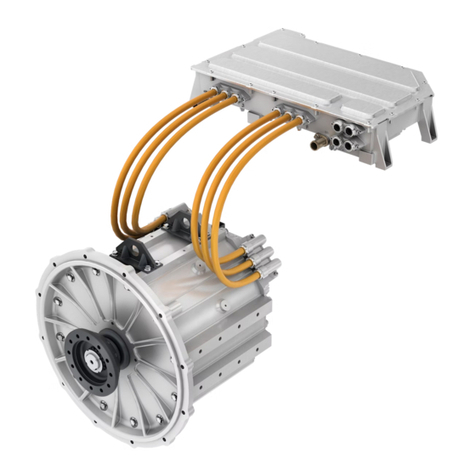
DANA TM4 SUMO MD MV User manual

1
SUMO MD MV/HV Powertrain
Troubleshooting Guide
March 2021

2
Safety Warnings
Safety Warnings
The description and specifications contained in the
service publication are current at the time of printing.
Dana TM4 reserves the right to discontinue or modify
its models and/or procedures and to change
specifications at any time without notice.
Any reference to brand name in this publication is
made as an example of the types of tools and
materials recommended for use and should not be
considered an endorsement. Equivalents may be
used.
Always use genuine Dana TM4 replacement parts.
Every effort has been made to endure the accuracy of
all information in this guide. However, Dana TM4
Commercial Vehicle Systems Division makes no
expressed or implied warranty or representation
based on the enclosed information.
Any errors or omissions may be reported to:
Marketing Services
Dana TM4 inc.
135, Joseph-Armand Bombardier, #25
Boucherville (Québec) J4B 8P1 Canada
IMPORTANT NOTICE
WARNING: Failure to follow indicated
procedures creates a high risk of
personal injury to the servicing
technician
CAUTION: Failure to follow indicated
procedures may cause component
damage or malfunction.
IMPORTANT: Highly recommended
procedures for proper service of this
unit
Note: Additional service information
not covered in the service procedures.
Tip: Helpful removal and installation
procedures to aid in the service of this
unit
This symbol is used throughout this
manual to call attention to procedures
where carelessness or failure to follow
specific instructions may result in
personal injury and/or component
damage.
Departure from the instructions, choice
of tools, materials and recommended
parts mentioned in this publication
may jeopardize the personal safety of
the service technician or vehicle
operator.
This symbol is used throughout this guide
to warn for electrical dangers. Failure to
abide to the related safety instructions
may result in personal injury and/or
component damage.
Departure from the instructions, choice of
tools, materials and recommended parts
mentioned in this publication may
jeopardize the personal safety of the
servicetechnicianorvehicle operator.
WARNING

3
Safety Warnings
This product generates high voltage that can cause
an electric discharge or electrocution resulting in
injury or death.
When installing the product, verify that:
•The traction battery (high-voltage battery) is
disconnected.
•The auxiliary battery (12V/24V battery) is
disconnected.
Care must be taken when manipulating electrical
equipment.
This product must be installed by qualified and
authorized personnel in accordance with applicable
vehicle standards and industry practices. Always use
appropriate insulation and protection before
manipulating the product even when the product is
disconnected from a high-voltage source.
Mishandling of this product may damage the
product and/or cause injury or death.
•All limitations and specifications
communicated by Dana TM4 regarding the
product must be respected.
•Do not attempt to open, repair or modify the
Motor Control Unit (MCU). In case of
damaged casing or suspected product
malfunction, contact Dana TM4 Customer
Service.
•Use only recommended points to lift and
secure the MCU.
•When using straps to lift the MCU, ensure
they do not touch or put pressure on any part
of the product exterior (surface, connectors,
and/or cables).
•Do not attach the motor to the MCU using a
shared support or bracket.
•Do not apply any external load to the casing
of the MCU.
The high-voltage cables MUST be shielded:
The external cables used for high voltage must be
orange and shielded; the high voltage and level of
current delivered by this product can be lethal.
Failure to shield the high-voltage cables will result in
non-compliance with EMI regulatory requirements.
This product uses differential mode capacitors
between the positive high-voltage DC bus (+) and the
negative high-voltage DC bus (-) and common mode
capacitors between the high-voltage DC bus and the
chassis.
Even when the product is disconnected from the
high-voltage source, these capacitors can hold a
voltage high enough to cause an electric discharge
or death.
WARNING
WARNING
WARNING

4
Safety Warnings
Regardless of the cooling system used, when in a
system, the MCU can be irreparably damaged and
may become unstable if the coolant liquid pressure
reaches or exceeds a pressure of 30 PSI (static
pressure measured at the entrance of the MCU
upstream of the MCU in the circuit).
Ensure that the pump is adjusted accordingly.
The cooling agent contains ethylene glycol that is a
highly flammable product. Ethylene glycol can burn
with an invisible flame that can cause serious burns
and/or other injuries.
Always handle the cooling agent carefully wearing
appropriate safety clothing and eye-glasses.
The cooling agent can irritate the skin, the eyes and
the mucous membranes.
•Always work in a well-ventilated area when
handling the cooling agent; breathing in high
concentrations of ethylene glycol can cause
nausea.
•In case of contact with eyes and skin, rinse
with water and consult a doctor.
•In case of ingestion, seek medical help
immediately.
The cooling agent is under pressure when heated;
removing the cap when the coolant is hot can cause
serious burns and/or other injuries.
Wait until the coolant reaches an ambient
temperature before removing the cap.
All potential dangers of handling cooling agents
cannot be listed here.
Consult manufacturer warnings and
recommendations for safe handling of the cooling
agent.
It is important to ensure that no voltage is present on
the high-voltage battery wires between both
polarities and from each polarity to chassis before
manipulation.
The vehicle integrator is responsible for ensuring that
proper training is given to all those who use this
system in order to avoid physical, electrical and
operational hazards.
CAUTION
WARNING

5
Table of Contents
Safety Warnings.......................................2
General Information.................................6
Acronyms - Symbols.................................................6
Key Features ............................................................7
Disclaimer.................................................................8
Safety Instructions....................................................8
Dana TM4 Motor and MCU Components.................9
System Specifications.............................................10
Component Description..........................................11
Simplified System Schematic .................................23
Diagnostics ............................................24
Diagnostics Tool .....................................................24
Installing the CAN drivers.......................................26
Connecting the CAN ports......................................26
Opening ODIN ........................................................27
Retrieve the SysFile ID...........................................27
SysFile ID Summary...............................................31
Table of SysFile ID .................................................31
Table of Troubleshooting Tree ...............................31
Table matching SysFile IDs and Troubleshooting
Trees.......................................................................32
Troubleshooting Tips..............................................33
Service Codes........................................34
Abbreviation and Definition.....................................34
Troubleshooting Trees Tables Details....................34
Troubleshooting Tree Legends...............................35
TT01: SysFile Cleared............................................36
TT02: Inconsistence in EEPROM memory section 38
TT03: Vaux too low.................................................40
TT04: Vaux too high ...............................................46
TT05: Hardware Failure Detected ..........................51
TT06: Abnormal Battery Current Condition............57
TT07: Phase Current Sensor Deactivated..............59
TT08: HVIL voltage input fault................................64
TT09: HVIL Output Fault.........................................69
TT10: Internal HVIL connection fault......................74
TT11: HVIL over current.........................................78
TT12: Initialization Timed Out.................................82
TT13: Invalid Motor Type or Phase Calibration......85
TT14: Invalid Hardware Version ............................ 87
TT15: Inconsistence of Protected EEPROM memory
section.................................................................... 89
TT16: Invalid Hardware or Software ...................... 91
TT17: Inconsistence between Control Logic and IGBT
............................................................................... 93
TT18: High power battery voltage < lower voltage limit
............................................................................... 95
TT19: High Power Battery Voltage > Maximum..... 99
TT20: IGBT Temperature Sensor reading over the
limit....................................................................... 105
TT21: Temperature Sensor reading over the limit107
TT22: EMI Temperature measurement over limit 109
TT23: Motor Coil Temperature Sensor measurement
over limit............................................................... 111
TT24: High Resolver Temperature ...................... 113
TT25: Internal Software Command Not Received
Properly................................................................ 115
TT26: IGBT Short Circuit Activated...................... 117
TT27: Phase Current reached Maximum............. 119
TT28: Phase Current Sum reached Maximum .... 121
TT29: Insufficient Defluxing Current at high speed123
TT30: AC current Torque Mismatch.................. 126
TT31: Phase Cable(s) Shorted to Chassis .......... 133
TT32: Motor Speed reached Maximum ............... 139
TT33: Critical low frequency process overrun...... 143
TT34: VMU Command Out-of-Range or Invalid .. 145
TT35: CAN Communication Error........................ 147
TT36: Position and/or Temperature Sensor Error 151
TT37: Sequencer error......................................... 153
STT01: Verify Connector Integrity........................ 155
STT02: Verify Cooling Circuit Integrity................. 157
Appendix .............................................. 160
Appendix 1: Table of SysFile ID........................... 160
Appendix 2: Table of Troubleshooting Trees....... 165
Appendix 3: Save EEPROM Sections ................. 171
Appendix 4: Retrieve GDD Files and User
Parameters........................................................... 172
Appendix 5: Cooling agent precautions............... 176
Appendix 6: Update Software .............................. 177
6
General Information
General Information
Acronyms - Symbols
A Ampere unit
AC Alternative Current
ACDC Alternative Current to Direct
Current
ASTM American Society for Testing and
Materials
Auxiliary Battery Standard 12V or 24V vehicle
battery
AWG American Wire Gauge
BIM Battery Interface Module
BMS Battery Management System
Board Net Standard 12V or 24V vehicle
network
CAN Control Area Network
communication protocol
CANxH CAN x High
CANxL CAN x Low
COS Cosinus
CRC Cyclic Redundancy Check
°C Degree Celsius unit
DC Direct Current
DCDC Chopper circuit DC to DC
DSP Digital Signal Processor
ECU Electronic Control Unit
EMF ElectroMotive Force
ESD ElectroStatic Discharge
EV Electrical Vehicle
Giga Ohm unit
GDD TM4 ODIN Gathered Diagnostic
Data sub program
h hour unit
HVIL Hazardous Voltage Interlock Loop
HS High Side
kW kiloWatt unit
KiloOhm unit
mA Milliampere unit
L Liter unit
L/h Liter per hour unit
Mega Ohm unit
MCU Motor Control Unit
Nm Newton meter unit
% Percentage
PC Personal Computer
PDU Power Distribution Unit
POC POwer Connector
P/N Part Number
PSI Pound-force per Square Inch unit
PWM Pulse Width Modulation
RPM Rotation Per Minute unit
SIN Sinus
SysFile ID Service Code
TM4 ODIN Dana TM4 diagnostic software
USB Universal Serial Bus
V Volt unit
Vaux Auxiliary battery voltage (12 V or 24 V)
VMU Vehicle Management Unit

7
General Information
Key Features
Dana TM4 Motor Control Unit (MCU)
The Motor Control Unit (MCU) system is operated via
CAN message communication between the MCU and
the Vehicle Management Unit (VMU) or Electronic
Control Unit (ECU).
The VMU or ECU is in charge of the user interface
and also interfaces with the Battery Management
System (BMS) and all other systems included in the
vehicle architecture.
The typical operation functions are:
•Applying power to the system from the
auxiliary battery.
•Asserting the enable signal to the MCU (VMU
/ECU or vehicle ignition).
•Performing high-voltage battery pre-charge
(VMU/ECU or BMS).
•Applying high-voltage battery voltage to the
system (BMS or BIM).
•Transmitting CAN messages (VMU/ECU)
with the MCU:
oStarting and stopping the system.
oApplying a mechanical torque.
oSafely shutting down the system.
oVerifying operational status.
Hazardous Voltage Interlock Loop (HVIL)
The Hazardous Voltage Interlock Loop (HVIL) internal
loop is closed, resulting in a short circuit between its
two input pins. The HVIL signal is used to open the
high-voltage battery contactor when its internal loop is
opened during product maintenance or repair (e.g.
removal of the MCU cover (MCU with removable side
cover) or disconnection of motor sensor cable)
thereby protecting the user.
Diagnostics Capability and Troubleshooting
Troubleshooting can be performed with the TM4
ODIN tool. It gives the list of events that occurred
during the operation and categorized the events such
as:
•Errors, which cause the product to cease
operation.
•Warnings and Information level events are
also recorded and must be taken into
consideration even though the product will
remain operational.

8
General Information
Disclaimer
Dana TM4 is not responsible for prolonged use of
product with one or more defective sensors as this
could cause permanent damage to the product and
injury
sensors fails, the vehicle must be returned to the
garage for inspection and repair.
Safety Instructions
This product must be installed and manipulated by
qualified personnel who are fully aware of the types of
hazards involved in working with electrical circuitry
and are familiar with standard practices for preventing
accidents. The vehicle integrator is responsible for
ensuring that proper training is given to all those who
use this system in order to avoid physical, electrical
and operational hazards.
Safety warning related to operating the system
Mishandling of this product may damage the product
and/or cause injury or death.
•Do not attempt to open or repair this product.
In case of damaged casing or suspected
product malfunction, contact Dana TM4.
•Use only recommended points to lift and
secure the system.
When manipulating and/or installing this product, you
must NOT:
•Modify any part of the MCU.
•Apply any external load to the casing of the
MCU.
Applying excessive torque or speed when the motor
is cold may negatively impact the durability of the
system.
When the motor is used in an environment with an
ambient temperature of below 0°C, it is recommended
that you avoid using excessive speed or torque and
follow a normal driving cycle for the first few minutes
until the motor vehicle mechanical equipment has had
a chance to warm up.
Note: This is a best practice commonly applicable to
any mechanical equipment. The Dana TM4 motor
does not limit performance; full speed and torque are
available, but not recommended, after a cold start.

9
General Information
Dana TM4 Motor and MCU Components (This is an example)
Dana TM4 Motor
Dana TM4 MCU

10
General Information
System Specifications
The motorization system is composed of the MCU and
motor.
Refer to the System Specification guide for your
system.
The table below is an example.
The MCU has the following connectors:
•Communication connector.
•Grounding Point.
•DC connectors.
•Phase Connectors.
•Motor Sensor Connectors.
•Coolant IN / OUT connectors.
Characteristics
Value
Electrical Specification
Traction Battery
Operating Voltage
300 - 750 VDC
Maximum non-operating voltage
775 VDC
Maximum current
615 ADC
Maximum Continuous Current
350 ADC
Auxiliary Battery
Operational range
8 - 32 VDC
Maximum non-operating voltage
36 VDC
Maximum steady state current
4.5 ADC @ 12 VDC; 3 ADC @ 24 VDC
Maximum inrush current
<10 ADC
Maximum quiescent current
<0.6mADC @ 8 VDC; <1.2mADC @ 32 VDC
Maximum System Efficiency
95.3%
CAN interface version
2.0b
Motor Control Unit Short-Circuit Protection
Yes
Motor Control Unit Over-Current Protection
Yes
System Specification
Characteristics
Designed
Measured
Maximum Mechanical Output Power
250 kW
265 kW for 47 seconds
Maximum Mechanical Output Torque
2645 Nm
2761 Nm for 30 seconds
Maximum Mechanical Output Torque at 0
RPM
2645 Nm
2731 Nm for 18 seconds
Continuous Mechanical Output Power
-
154 kW
Continuous Mechanical Output Torque
-
969 Nm
Normal Operating Range
0 - 3500 RPM
Derating Range
3500 3700 RPM
Overspeed Range
3700 4200 RPM for less than 2 minutes
Environmental and cooling features
Coolant temperature*
-40 °C to 85 °C
Ambient temperature*
-40 °C to 85 °C
Storage Temperature
-40 °C to 85 °C
Cooling System
40% deionized water / 60% glycol
Motor and MCU maximum allowed working
pressure
30 PSI
Motor Coolant Flow Rate
1200L/h
MCU Coolant Flow Rate
1200L/h

11
General Information
Component Description
Communication connector
An interface harness is used between the MCU and
the VMU/ECU. The communication harness that is
connected to the MCU contains all required signals to
interface the MCU with the VMU/ECU, including the
enable signal, the CAN ports and the CAN signals.
Type 2 connector
The communication connector has 23 pins with the
following specification:
VMU/ECU interface harness –Plug pinout specifications 1-776228-1 (Type 2)
PIN
Signal Name
Types
AWG
Description
1
Ignition
Input
20-16
Enable signal to the Motor Control Unit.
2
CAN2L
Communication
20-16
Low level of differential signal CAN2.
3
CAN SHIELD
Ground/Shield
20-16
Typical CAN shield.
4
PWM1_OUT
Low side output
20-16
Generic Low side Output 1A, can be used as PWM.
5
ANALOG1
Input
20-16
-
6
DIGITAL INPUT 1
Input
20-16
-
7
HS_OUT
High side Output
20-16
Generic high side output 200mA.
8
Vaux+
Power
20-16
Positive power wire of the MCU. Must be connected to the
auxiliary battery using fuse type.
9
CAN1L
Communication
20-16
Low level of differential signal CAN1.
10
CAN2H
Communication
20-16
High level of differential signal CAN2.
11
5V SENSOR
Analog supply
20-16
-
12
PWM2_OUT
Low side output
20-16
Generic Low side Output 1A, can be used as PWM.
13
ANALOG3
Input
20-16
-
14
DIGITAL INPUT 3
Input
20-16
-
15
Vaux+
Power
20-16
Positive power wire of the MCU. Must be connected to the
auxiliary battery using fuse type.
16
CAN1H
Communication
20-16
High level of differential signal CAN1.
17
GND_SENSORS
Ground
20-16
-
18
HVIL_IN
HVIL IN
20-16
Hazardous voltage interlock loop (200mA max).
19
HVIL_OUT
HVIL OUT
20-16
Hazardous voltage interlock loop (200mA max).
20
ANALOG2
Input
20-16
-
21
DIGITAL INPUT 2
Input
20-16
-
22
Vaux-
Reference
20-16
Must be connected to the vehicle chassis (frame/auxiliary
battery -).
23
Vaux-
Reference
20-16
Must be connected to the vehicle chassis (frame/auxiliary
battery -).

12
General Information
Type 1 connector
The communication connector has 12 pins with the following specification:
VMU/ECU interface harness –Plug pinout specifications –P770E0106 (Type1)
PIN
Signal Name
Types
AWG
Description
A
CAN1L
Communication
20-22
Low level of differential signal CAN1.
B
CAN1H
Communication
20-22
High level of differential signal CAN1.
C
CAN2L
Communication
20-22
Low level of differential signal CAN2.
D
CAN2H
Communication
20-22
High level of differential signal CAN2.
E
Vaux+
Power
20-22
Positive power wire of the MCU. Must be connected to
the auxiliary battery using fuse type.
F
Vaux+
Power
20-22
Positive power wire of the MCU. Must be connected to
the auxiliary battery using fuse type.
G
Ignition
Input
20-22
Enable signal to the Motor Control Unit.
H
Emergency stop
Output
20-22
Emergency stop.
J
HVIL_IN
HVIL IN
20-22
Hazardous voltage interlock loop (200mA max).
K
HVIL_OUT
HVIL OUT
20-22
Hazardous voltage interlock loop (200mA max).
L
Vaux-
Reference
20-22
Must be connected to the vehicle chassis
(frame/auxiliary battery -).
M
Vaux-
Reference
20-22
Must be connected to the vehicle chassis
(frame/auxiliary battery -).

13
General Information
Grounding Point
The grounding point connection prevents functional
issue to the motorization system, and ensures the
user safety in case of an insulation fault. An incorrectly
grounded connection may result in functionality
losses and safety risks for the user. Grounding straps
must be connected to their dedicated connection
points (on the MCU and the motor) to the vehicle
chassis frame.
The vehicle chassis connection points for the MCU
and motor grounding straps should ideally be the
same point, or the same vehicle chassis frame side.
Conductive grease should be used on each of the
contact points to ensure reliable and durable
grounding connections. The resistance between the
grounding points and the chassis must be tested each
time the connection is impacted. The resistance must
be less than 0.1 Ohm.
MCU and motor grounding point locations
(product type example)

14
General Information
Motor Phase Connectors
Power cables are required between the MCU and the
motor to connect each phase. An example of a
product with a view of the phase cable connection
points is shown below.
Phase Cable Identification (Straight Terminal)
Phase Cable Identification (90 degrees)

15
General Information
Motor Sensor Cables
The Motor and the MCU must be connected together
by motor sensor cables. Therefore, a motor sensor
interface harness is required between the motor and
the MCU.
Motor sensor connector pinout mapping from Dana TM4 MCU to TM4 motors
MCU
Type 1
MCU
Type 2
Signal name
TM4 Motor
Type 1
TM4 Motor
Type 2
A
1
Temperature C-
A
F3
B
9
Temperature C+
B
F2
C
16
Temperature B-
C
A3
D
2
Temperature B+
D
A2
E
10
Temperature A-
E
A4
F
17
Temperature A+
F
B4
J
3
R1_OUT
N
A1
T
11
R2_OUT
P
B1
L
18
COS+ (S1)
L
C1
M
4
COS- (S3)
M
D1
N
12
SIN+ (S2)
J
E1
P
19
SIN- (S4)
T
F1
H
5
HVIL_TO_MOTOR
H
F4
R
13
1 Wire OUT
R
C2
S
20
1 Wire GROUND
S
C3
K
6
HVIL_FROM_MOTOR
K
E4
V
N/C
Chassis
V
N/C
MCU connector type 2
MCU connector type 1

16
General Information
Motor connector head Identification
Dana TM4 MCU A3 (Type 2)
Dana TM4 Motor (Type 2)
Dana TM4 MCU A1/A2 (Type 1)
Dana TM4 motor (Type 1)

17
General Information
Connecting Auxiliary Battery to MCU
The Auxiliary Battery provides power to the MCU. The
negative terminal of the battery must be connected to
the frame of the vehicle (chassis).
Auxiliary Battery Fuse
To protect the system against short circuit, a fuse is
connected in series with the positive terminal of the
auxiliary battery.
Specifications
Units
Values
(12 V)
Values
(24 V)
Maximum
MCU steady
state current
A
4.5
3
Maximum
MCU inrush
current
A
< 10
< 10
Maximum
MCU
quiescent
current
mA
< 1
< 1.5
Note: Refer to the Installation guide for further details.

18
General Information
Embedded software packages
The software installation package includes several
embedded files:
•The embedded software package executable
•A basic TM4 ODIN file (.odn4).
The next chart shows the embedded software
package files:
Note on software package naming
A------------------ IGBT technology ex. HP2
B------------------ Operating voltage type (L, M or H) ex. HV
C------------------ Number of 3 phase systems with number of phases ex. 0206
D------------------ Software develop by ex. TM4
E------------------ Motor type ex MO340
F------------------ Motor size ex. 240
G ----------------- Software family letter ex. A
H------------------ Software version (Major, minor, delivery and change list) ex. 3.6.1.95366
As an example, here is a typical software package file name:
MCU_INVHP2HV_0206_TM4_MO340_240_A_V3.6.1.95366Pkg.exe
File
Name
Description
Embedded Software
Package Executable
MCU_INV- ABCDEFGH Pkg.exe
(See note on software PACKAGE
naming)
Embedded software files
used for firmware update.
Basic TM4 ODIN file
(Part of the embedded
software package
accessible with TM4
ODIN)
UserInterface.odn4
Basic file used within TM4
ODIN to see software
variables.

19
General Information
Coolant In / Out
As power is delivered to the wheels, temperatures of
the various components within the motor and the
MCU rise. Therefore, a cooling unit/radiator must be
installed in the vehicle and connected to the MCU and
the motor to dissipate the excess heat.
The motor and the MCU are linked to the cooling
system by a fan/pump/coolant tank and radiator
configuration. There are two possible configurations
for the cooling system: the parallel configuration and
serial configuration.
Parallel Configuration
Serial Configuration
MCU example with coolant inlet and outlet indications

20
General Information
Coolant Specification
Safety precaution
Regardless of the cooling system used, the product
can be damaged if the coolant temperature is allowed
to exceed the maximum temperature specified in your
system specifications document. The MCU will apply
a derating mode as a protection to reduce the
sys
Also, the static pressure of the coolant system should
never be allowed to exceed 30 PSI. Doing so, may
overcome internal sealing breach and cause
damages to the unit:
•Ensure that the cooling system components
are adjusted correctly to respect these limits.
Recommendations
To prevent corrosion in cooling systems, these
recommended best practices must be followed.
•The cooling circuit must be rinsed with de-
ionized water each time before filling.
•The ethylene glycol must respect the
standard corresponding to its application
(ASTM D3306 Type III or ASTM D6210 Type
III).
•The ethylene glycol must contain some type
of active corrosion inhibitors.
•The ethylene glycol must be diluted with de-
ionized water (not distilled water).
•The dilution ratiomustbe 60% ethylene glycol
to 40% de-ionized water (minimally 50%
ethylene glycol to 50% de-ionized water).
•Two different types of coolant should not be
mixed.
As the cooling unit, cooling hose and cooling agent
are not supplied by Dana TM4, the vehicle integrator
has full responsibility for following specifications and
operating methods given by the system specifications
and the provided products interface drawings (MCU
and motor).
In order to meet Dana TM4 specifications and to
obtain maximum system performance, the
temperature of the coolant and coolant flow must
comply with the requirements as specified in the
system specifications of your system. Above these
thresholds, the system can degrade the output torque
to protect its internal components from overheating.
When using the MCU in a vehicle cooling
configuration, there can be associated drops in
pressure that have to be managed. Coolant pressure
drops can be affected by the temperature of each
s for
more information.
WARNING
Other manuals for TM4 SUMO MD MV
1
This manual suits for next models
1
Table of contents
Other DANA Industrial Equipment manuals

DANA
DANA Spicer AXSM0056 User manual

DANA
DANA SPICER Torque-Hub FBH04 Wet Series User manual

DANA
DANA Brevini Posiplan PH Series Manual

DANA
DANA SPICER Axle 123 User manual

DANA
DANA SPICER 6000 EHO User manual

DANA
DANA SPICER AXLE 212 User manual

DANA
DANA NoSPIN S140 User manual

DANA
DANA SPICER Torque-Hub S6B Installation instructions

DANA
DANA SPICER TM4 SUMO HP HV Powertrain User manual

DANA
DANA MO213S10 Setup guide